EP0374251A1 - Anordnung zum trennen von ferromagnetischen materialien aus flüssigen medien - Google Patents
Anordnung zum trennen von ferromagnetischen materialien aus flüssigen medien Download PDFInfo
- Publication number
- EP0374251A1 EP0374251A1 EP88908415A EP88908415A EP0374251A1 EP 0374251 A1 EP0374251 A1 EP 0374251A1 EP 88908415 A EP88908415 A EP 88908415A EP 88908415 A EP88908415 A EP 88908415A EP 0374251 A1 EP0374251 A1 EP 0374251A1
- Authority
- EP
- European Patent Office
- Prior art keywords
- plates
- projections
- lining
- working chamber
- orifices
- Prior art date
- Legal status (The legal status is an assumption and is not a legal conclusion. Google has not performed a legal analysis and makes no representation as to the accuracy of the status listed.)
- Withdrawn
Links
- 239000012530 fluid Substances 0.000 title claims abstract description 85
- 239000003302 ferromagnetic material Substances 0.000 title claims description 20
- 230000005291 magnetic effect Effects 0.000 claims abstract description 99
- 230000005294 ferromagnetic effect Effects 0.000 claims abstract description 34
- 230000005415 magnetization Effects 0.000 claims abstract description 18
- 239000002245 particle Substances 0.000 claims abstract description 18
- 239000012535 impurity Substances 0.000 claims description 55
- 230000001154 acute effect Effects 0.000 claims description 26
- 230000006698 induction Effects 0.000 claims description 12
- 230000007423 decrease Effects 0.000 claims description 10
- 241000446313 Lamella Species 0.000 claims description 5
- 230000003993 interaction Effects 0.000 claims description 3
- 239000013013 elastic material Substances 0.000 claims 1
- 238000004140 cleaning Methods 0.000 description 34
- 238000012856 packing Methods 0.000 description 16
- 238000000926 separation method Methods 0.000 description 16
- 230000008929 regeneration Effects 0.000 description 15
- 238000011069 regeneration method Methods 0.000 description 15
- 230000009471 action Effects 0.000 description 12
- XLYOFNOQVPJJNP-UHFFFAOYSA-N water Substances O XLYOFNOQVPJJNP-UHFFFAOYSA-N 0.000 description 8
- 238000004519 manufacturing process Methods 0.000 description 7
- 238000001556 precipitation Methods 0.000 description 7
- 238000001914 filtration Methods 0.000 description 6
- 239000000463 material Substances 0.000 description 6
- 230000035699 permeability Effects 0.000 description 6
- 239000006185 dispersion Substances 0.000 description 5
- 239000007788 liquid Substances 0.000 description 5
- 230000006835 compression Effects 0.000 description 3
- 238000007906 compression Methods 0.000 description 3
- 238000013461 design Methods 0.000 description 3
- 238000010586 diagram Methods 0.000 description 3
- 238000000034 method Methods 0.000 description 3
- 230000004048 modification Effects 0.000 description 3
- 238000012986 modification Methods 0.000 description 3
- QGZKDVFQNNGYKY-UHFFFAOYSA-N Ammonia Chemical compound N QGZKDVFQNNGYKY-UHFFFAOYSA-N 0.000 description 2
- 238000010521 absorption reaction Methods 0.000 description 2
- 230000015572 biosynthetic process Effects 0.000 description 2
- 238000006243 chemical reaction Methods 0.000 description 2
- 238000009826 distribution Methods 0.000 description 2
- 238000005265 energy consumption Methods 0.000 description 2
- 239000007789 gas Substances 0.000 description 2
- 239000000203 mixture Substances 0.000 description 2
- 239000003921 oil Substances 0.000 description 2
- 239000002244 precipitate Substances 0.000 description 2
- 230000008569 process Effects 0.000 description 2
- 239000000047 product Substances 0.000 description 2
- OKTJSMMVPCPJKN-UHFFFAOYSA-N Carbon Chemical compound [C] OKTJSMMVPCPJKN-UHFFFAOYSA-N 0.000 description 1
- 241000639939 Philaccolilus mas Species 0.000 description 1
- 229910000831 Steel Inorganic materials 0.000 description 1
- 239000002253 acid Substances 0.000 description 1
- 150000007513 acids Chemical class 0.000 description 1
- 238000013019 agitation Methods 0.000 description 1
- 229910021529 ammonia Inorganic materials 0.000 description 1
- 230000033228 biological regulation Effects 0.000 description 1
- 238000007664 blowing Methods 0.000 description 1
- 229910052799 carbon Inorganic materials 0.000 description 1
- 238000005056 compaction Methods 0.000 description 1
- 238000010276 construction Methods 0.000 description 1
- 238000005260 corrosion Methods 0.000 description 1
- 230000007797 corrosion Effects 0.000 description 1
- 230000003247 decreasing effect Effects 0.000 description 1
- 238000000151 deposition Methods 0.000 description 1
- 238000006073 displacement reaction Methods 0.000 description 1
- 238000005553 drilling Methods 0.000 description 1
- 230000000694 effects Effects 0.000 description 1
- 230000005489 elastic deformation Effects 0.000 description 1
- 230000008030 elimination Effects 0.000 description 1
- 238000003379 elimination reaction Methods 0.000 description 1
- 238000002474 experimental method Methods 0.000 description 1
- 238000011049 filling Methods 0.000 description 1
- 230000004907 flux Effects 0.000 description 1
- -1 for example Substances 0.000 description 1
- 230000005484 gravity Effects 0.000 description 1
- 238000002955 isolation Methods 0.000 description 1
- 230000007246 mechanism Effects 0.000 description 1
- 239000002184 metal Substances 0.000 description 1
- 230000005298 paramagnetic effect Effects 0.000 description 1
- 238000005192 partition Methods 0.000 description 1
- 230000002093 peripheral effect Effects 0.000 description 1
- 239000011148 porous material Substances 0.000 description 1
- 230000010349 pulsation Effects 0.000 description 1
- 230000000717 retained effect Effects 0.000 description 1
- 238000005096 rolling process Methods 0.000 description 1
- 239000005060 rubber Substances 0.000 description 1
- 239000010959 steel Substances 0.000 description 1
- 239000000126 substance Substances 0.000 description 1
- 238000005406 washing Methods 0.000 description 1
- 239000002912 waste gas Substances 0.000 description 1
- 239000002351 wastewater Substances 0.000 description 1
Images


Classifications
-
- B—PERFORMING OPERATIONS; TRANSPORTING
- B03—SEPARATION OF SOLID MATERIALS USING LIQUIDS OR USING PNEUMATIC TABLES OR JIGS; MAGNETIC OR ELECTROSTATIC SEPARATION OF SOLID MATERIALS FROM SOLID MATERIALS OR FLUIDS; SEPARATION BY HIGH-VOLTAGE ELECTRIC FIELDS
- B03C—MAGNETIC OR ELECTROSTATIC SEPARATION OF SOLID MATERIALS FROM SOLID MATERIALS OR FLUIDS; SEPARATION BY HIGH-VOLTAGE ELECTRIC FIELDS
- B03C1/00—Magnetic separation
- B03C1/02—Magnetic separation acting directly on the substance being separated
- B03C1/025—High gradient magnetic separators
- B03C1/031—Component parts; Auxiliary operations
- B03C1/033—Component parts; Auxiliary operations characterised by the magnetic circuit
- B03C1/034—Component parts; Auxiliary operations characterised by the magnetic circuit characterised by the matrix elements
-
- B—PERFORMING OPERATIONS; TRANSPORTING
- B01—PHYSICAL OR CHEMICAL PROCESSES OR APPARATUS IN GENERAL
- B01D—SEPARATION
- B01D35/00—Filtering devices having features not specifically covered by groups B01D24/00 - B01D33/00, or for applications not specifically covered by groups B01D24/00 - B01D33/00; Auxiliary devices for filtration; Filter housing constructions
- B01D35/06—Filters making use of electricity or magnetism
-
- B—PERFORMING OPERATIONS; TRANSPORTING
- B03—SEPARATION OF SOLID MATERIALS USING LIQUIDS OR USING PNEUMATIC TABLES OR JIGS; MAGNETIC OR ELECTROSTATIC SEPARATION OF SOLID MATERIALS FROM SOLID MATERIALS OR FLUIDS; SEPARATION BY HIGH-VOLTAGE ELECTRIC FIELDS
- B03C—MAGNETIC OR ELECTROSTATIC SEPARATION OF SOLID MATERIALS FROM SOLID MATERIALS OR FLUIDS; SEPARATION BY HIGH-VOLTAGE ELECTRIC FIELDS
- B03C2201/00—Details of magnetic or electrostatic separation
- B03C2201/18—Magnetic separation whereby the particles are suspended in a liquid
Definitions
- the present invention relates to devices for the separation of ferromagnetic materials from fluids.
- the device for separating ferromagnetic materials from fluids described in SU-A-1029990 includes a cylindrical working chamber on the outside of which is placed the magnetization system and inside, a ferromagnetic packing designed in the form of orifice plates.
- the working chamber is provided with inlet and outlet pipes for the cleaned fluid.
- the orifice plates are regularly distributed over the height of the chamber.
- between the plates are formed slotted spaces through which passes the flow of fluid to be cleaned.
- the precipitation of impurities from the medium to be cleaned takes place on the edge of the orifices of the plates where zones of inhomogeneous magnetic field are formed.
- the force action of the inhomogeneous magnetic field on the particles of impurities in these areas is quite weak.
- the plates are rigidly linked to each other without the possibility of reciprocal displacement and isolation, which hinders the efficiency of the regeneration and, respectively, of good quality washing of the plates of the impurities retained.
- the device for separating ferromagnetic materials from fluids is also known (SU-A-1152618) comprising a working chamber provided with a ferromagnetic lining in the form of numerous plates with through orifices, having profiled projections oriented at an angle around the contour. relative to the plate, a magnetization system adapted to react on the ferromagnetic lining and to magnetize it, an inlet pipe to supply the working chamber with fluid to be cleaned and an outlet pipe to receive the fluid cleaned after its passage through the lining.
- the plates having orifices of the same dimensions comprise profiled projections forming numerous zones of inhomogeneous magnetic field whose value in these zones is of a higher order than in the plates with orifices without projection.
- This device works effectively when cleaning fluids containing particles of impurities that are homogeneous in size and magnetic properties.
- the modification of the type of the medium to be cleaned, containing different impurities in size and in properties implies a modification of dimensions and arrangement of the lamellar lining having different orifices and profiled projections. A considerable influence on the cleaning efficiency and on the choice of filling is also exerted by the viscosity of the medium to be cleaned.
- Plates with identical dimensions of the orifices, projections with a similar arrangement lead to the fact that, during the cleaning of the fluids in the device, the parts of the volume of the lining at the height of the chamber operate in an inadequate cleaning regime.
- the lower parts (near the inlet tubing) of the packing volume "become clogged" with impurities quickly, the medium ones, more slowly and those at the top (of the outlet tubing), even more slowly. Then, the time between two successive periods of the generation regimes will be defined by the operation of the lower layers of the lining, that is to say the filtration period will be reduced.
- the actual fluids to be cleaned contain particles of impurity whose dimensions vary in a wide range from 0.01 to 10 ttm and more, while the required level of cleaning of fluids, for example , metallurgical circulation water, condensates from electrical and thermal power plants, must be increased to the residual content of impurities from 10 -4 to 1 0- 9 p.mas.
- the impurities have different magnetic properties: from paramagnetic to ferromagnetic, while the fluids to be cleaned vary from gases to condensates and oils whose viscosity is different.
- the known device due to its constitutive features, cannot provide the required level of cleaning of media containing impurities of different dimensions, of various magnetic properties, to create adequate effective cleaning conditions throughout the volume of the lining.
- the problem posed at the basis of the invention is to develop a device for the separation of ferromagnetic materials from fluids, having such a constitution of the ferromagnetic lining that it would ensure effective cleaning of fluids of different viscosities and containing ferromagnetic particles of different sizes and properties while reducing energy consumption.
- the invention consists of a device for the separation of ferromagnetic materials from fluids, of the type comprising a working chamber provided with a ferromagnetic lining in the form of numerous plates pierced with through holes, provided on the contour with profiled projections, oriented under a angle with respect to the plate, a magnetization system suitable for interacting with and for magnetizing the ferromagnetic lining, an inlet pipe for supplying the working chamber with fluid to be cleaned and an outlet pipe for receiving the fluid cleaned after its passage through the lining, according to the invention, the arrangement of the orifices on the plate, their dimensions, their configuration, the dimensions and the shape of the projections, the distance between the plates are variable in the volume of the working chamber according to the magnetic properties of the impurity particles of the fluid to be cleaned, their dimensions (dispersion), the con centration and viscosity of the fluid.
- the plates To ensure the variation of the difference between the plates up to the required value, it is recommended to make the plates from flexible material, give them an identical curvilinear shape and place between them elastic inter-blades.
- elastic interleaves As elastic interleaves, it is possible to use elements that are simple to manufacture and ensuring, if necessary, a different degree of compression of several plates and also ensuring the presence or absence of contact of the profiled projections and of the surface of the adjacent plates during plugging or unplugging the magnetic field.
- At least one auxiliary source of magnetic field located outside the working chamber of the device so that the vector of its magnetic field, implying during connection and of the disconnection a magnetic reaction of the lamellar lining, either oriented along the axis of the working chamber and allows to compress, if necessary, the plates to a minimum possible distance, or by releasing the plates, it is that is, by increasing the gap between the plates to a required value.
- the preceding plate of the ferromagnetic lining can be connected by the end at the beginning of each following plate so that, along the axis of the working chamber, a strip of zigzag plates is formed.
- the plates can be placed parallel to each other and the gap between two adjacent plates can be made smaller from the inlet manifold to the outlet manifold.
- the height of the profiled projection must be equal to the distance between two adjacent plates so that the ends of the projections of the previous plates are in contact with the surfaces of the following plates.
- the profiled projections can be manufactured in the form of rings of variable section, increasing from the top of the projection to its base .
- the height of the lower profiled projections as a function of the difference between two adjacent plates and to provide these plates, at the place of these orifices, with concave and convex areas whose depth, relative to the plane of the plate, ensures in combination with the height of the profiled projection, the contact of the latter with the surface of the adjacent plate.
- the plates can be provided with additional profiled projections in the form of stems.
- the rods rigidly fixed to the even plates, can then have a length equal to the distance between all the two adjacent odd plates.
- the stems may have a length less than the gap between all two neighboring odd plates.
- rods in the form of a bundle of flexible ferromagnetic wires.
- the rods can also have a variable cross section.
- rods can be in the form of tubes and, therefore, the hydraulic resistance of the packing is reduced.
- the magnetization system is a solenoid
- the magnetization system is a bipolar electromagnet whose poles are contiguous on the surface of the working chamber where the direction of the current of the fluid to be cleaned is oriented transverse to the induction vector of the magnetic field, it It is recommended to distribute the profiled projections on the plate so that their number, in the zone of each plate furthest from the poles of the electromagnet, increases.
- the plates having the form of cylindrical surfaces coaxial and concentric with the working chamber, while defining the gap between the adjacent plates in decrease from the inlet manifold to the outlet manifold.
- the advantages of the device for the separation of ferromagnetic materials from fluids consist in that following the choice and the design, the ferromagnetic lining, the arrangement of the orifices on the plate, their size, configuration, dimensions and shape of the projections, the difference between the variable plates in the volume of the working chamber as a function of the magnetic properties of the particles of ferromagnetic impurities in the fluid to be cleaned, their dimensions (dispersion), the concentration and the viscosity of the fluid, we ensure, with a low admissible energy consumption, a high required level of cleaning of a fluid as well liquid as gaseous, as well with important viscosity as weak, with various dimensions of the particles of impurities and with different magnetic properties.
- the regeneration of the ferromagnetic lining is carried out quickly and efficiently.
- the packing density of the packing is a simple technique to regulate using auxiliary magnetic field sources, placed outside the working chamber and guaranteeing the magnetic interaction with the lamellar packing.
- the equipment of the device, according to the invention, of additional profiled projections in the form of ferromagnetic rods, placed and fixed on the odd plates of the stack, makes it possible to increase the density of the packing of the lining, the average induction of the field in the packing, the number of zones of the high gradient magnetic field and the degree of cleaning of the fluid.
- the shape and dimensions of the rods are selected based on the type of fluid to be cleaned and the degree of cleaning desired.
- uniform "stacking" of impurity particles is provided over the entire volume of the lining and an increase, for this purpose, in the degree of cleaning and in the operating time of the device for an equal cleaning regime due to the number of projections, their height, the difference between the plates which are variable in height and in diameter depending on the chamber, for example, it is possible to provide that the difference between the plates decreases from the inlet manifold to the outlet manifold.
- the device proposed for the separation of ferromagnetic materials from the fluids comprises a single working chamber 1.
- the chamber 1 is formed by a cylindrical body 2 with end covers 2 ', and in which there is a ferromagnetic lining 3, in the form of numerous plates 4 flat and flexible, pierced with through holes 5 and provided on the periphery with profiled projections 6 in the form of acute lamellas oriented along a given angle with respect to the plane of the plates 4.
- part of the profiled projections 6 is provided with additional through holes 5 ′ having auxiliary acute lobes 7.
- Between the plates 4 are elastic interleaves 8, for which a material such as gum resistant to water and acids, rubber, and other known elements such as seals can be used. elastic.
- the device also includes a magnetization system 9 located outside the chamber 1, constituted in the version given by a multi-layer solenoid 10.
- a magnetization system 9 located outside the chamber 1, constituted in the version given by a multi-layer solenoid 10.
- the working chamber 1 is provided with an auxiliary source 11 of magnetic field, located outside the chamber 1 on the upper cover 2 'and which ensures a magnetic interaction of force with the lamellar packing 3.
- a second auxiliary source is placed on the lower cover 2 'of the chamber (not shown in the figure).
- the source 11 of magnetic field is an electromagnet comprising a ferromagnetic core 12 and an electric coil 13.
- the source 11 can also be a solenoid in the case where the diameter of the body 2 is very large, for example more than 0.5 m. In this case, it is more practical to place the auxiliary source 11 of the magnetic field on the surface lateral of the body 2, concentrically thereto, in a manner analogous to the solenoid 10.
- tubes, inlet and outlet 14, 15 respectively.
- the plates 4 have the form of flat discs, arranged parallel to one another, the gap between them decreases from the inlet tubing 14 to the tubing outlet 15.
- the number of main profiled projections 6 and auxiliary lobes 7, their height and the dimensions of the orifices 5 and 5 ′ also vary from the inlet pipe 14 to the outlet pipe 15.
- the distance between the plates 4 is adjusted using the elastic interleaves 8 which, by compressing or releasing under the action of the plates and under the effect of the auxiliary source of magnetization 11 of magnetic field and of the solenoid-10, provide the necessary density of stacking of the lining 3 and bringing the projections 6 into contact or not with the surface of the plates 4.
- the average value of the induction of the magnetic field in the lining 3 and the number of zones of inhomogeneous magnetic field increase when the height of the profiled projections 6 is reduced, that the number of orifices 5, 5 ′ is increased per unit. of the surface of the plates 4 in the direction of the movement of the fluid to be cleaned, as shown in FIGS. 2, 3.
- the force action of the field on the impurity particles increases due to the formation, in the acute main lamellae, of profiled projections 6.
- additional orifices 5 ′ bordered by the acute auxiliary lobes 7 and folded down in a given angle with respect to the surface of the main strip 6 provided with additional orifices 5 ′ increases along the chamber 1 from the inlet pipe 14 to the outlet pipe, as shown in FIGS. 1, 2, 3.
- a version of the device according to the invention represented in FIGS. 4, 5 and 6, different from the version of FIGS. 1, 2 and 3, comprises the flexible curved plates 4 ′ and a second auxiliary source 16 of magnetic field constituted by an electro -magnet located outside chamber 1 on the lower cover 2 '.
- the source 16 of magnetic field comprises a core 17 and an electric coil 18 and is placed analogously to the source 11 of magnetic field.
- the plates 4 ' are curvilinear, have the same curvature and are arranged in height relative to the chamber 1 regularly, at the same distance from each other.
- the profiled projections 6 have additional orifices 5 ′, bordered by the auxiliary lobes 7 folded down at a given angle relative to the plane of the projections 6.
- the number of main projections 6 increases along the chamber 1 from the inlet pipe 14 to the outlet pipe (to simplify the figures, the orifices 5 'and the projections 7 are not shown in Figures 4, 5, 6, since 'they have a shape identical to that of the projections 7 and orifices 5' of Figures 2 and 3).
- a ferromagnetic envelope 19 is placed outside the solenoid 10, this making it possible to reduce the magnetic field losses in the environment.
- the electromagnet 16 provides the necessary regulation of the density of the lamellar lining 3, the counting down and the compression of the plates 4 '.
- the second auxiliary source 16 of magnetic field is especially recommended in the case where the thickness of the layer of the lining 3 reaches 1.0 m and more and in the case where it is necessary to intensify the agitation of the plates 4 ′ to evacuate, by example, strongly magnetic impurities from the surface of the plates 4 '.
- Figures 5, 6 show the positions of the plates 4 'in the cleaning regime ( Figure 5) and in the regeneration regime ( Figure 6).
- the profiled projections 6, in the form of acute lamellae of the upper plate 4 ′ are in contact with the surface of the lower plate 4 ′ by forming a zone of high gradient magnetic field at the points where the impurity precipitation process.
- the regeneration takes place following the disjunction of the contact points of the profiled projections 6 and of the surface of the plates 4 ′ (FIG. 6) under the action of the sources 11, 16 of the magnetic field and of the elastic interleaves 8.
- Figures 7, 8, 9 show a version of the device where the curvilinear plates 4 'are arranged in the working chamber 1 alternately: a concave plate 4' and the next convex, between each plate interposed an elastic inter-blade 8.
- Such an alternating arrangement of curvilinear plates 4 ′ having elastic properties allows, in a wide range, to modify the density of the stack of packing 3 simply from a technical point of view, to increase or reduce the number of points of contact of the projections 6 and of the plates 4 'and respectively the number of the zones of inhomogeneous magnetic field.
- the number of profiled projections 6 increases in the direction of movement of the fluid in the chamber 1.
- the profiled projections 6 are not provided with additional orifices 5 ′, but from mid-height of the layer of lamellar lining 3, the additional orifices 5 'respectively, the additional projections in the form of acute lobes 7 appear in the profiled projections 6.
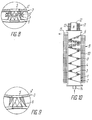
- a version of the device represented in FIG. 10, different from the version of FIG. 1, comprises the plates 4 with profiled projections 6, connected in such a way that each preceding plate 4 is connected by its end to the beginning of the next plate 4 and thus , along the axis of the working chamber 1, is formed a strip of plate 4 in a zigzag.
- the lamellar lining 3 in the form of a zigzag strip ensures a clear disjunction of the plates 4 and a furnishing of the precipitated deposits, which contributes to the regeneration to the required level, especially when cleaning very concentrated and oily fluids, for example, when cleaning circulation water which requires a low stack density and a reduced thickness of the lining layer.
- FIG. 11 represents a version of the device according to the invention in which the curved flexible plates 4 ′ are arranged alternately so that one is concave and the next convex.
- the plates 4 ' are oriented along the surface along the axis of the working chamber 1.
- the disjunction and the vibration of the plates 4' in regeneration mode are carried out using the electromagnets 20 located on the lateral surface of the working chamber 1.
- the electromagnets 20, each consisting of a core 21 and an electric coil 22, are distributed in height in working chamber 1 and can operate independently of each other.
- the solenoid 10 is designed with separate sections, distributed in height in the chamber 1.
- the cores 21 of the electromagnets 20 are oriented perpendicular to the plane of the plates 4 'and are placed in the spaces between the sections of the solenoid 10 and are moreover closely applied by their ends to the lateral surface of the chamber 1.
- the plates 4 ′ are agitated by pulsation, which causes the disjunction of the plates 4 ', the furnishing of the deposits of the impurity particles so as to facilitate their evacuation.
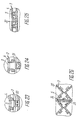
- a version of the device shown in Figures 12, 13 differs from the version of Figure 1 in that the plates 4 are provided with additional profiled projections 23 in the form of rods of length equal to the distance between all the two adjacent odd plates 4 , rigidly fixed in the 4 pair plates.
- the ferromagnetic rods 23 can have the shape of acute segments 24 (FIGS. 14, 15) with grooves on the external surface or even have the shape of acute segments 25 (FIG. 16) with variable cross section and narrowed in the central and enlarged part. at the ends, or in the form of a bundle of fine flexible wires 26 (Figure 17), or in the form of pointed rods 27 ( Figure 18), or in the form of tubes 28 ( Figures 19, 20) with fluted ends .
- the rods 23 have a length less than the distance between the neighboring 4 odd plates ( Figures 12, 13).
- An advantageous use of a lamellar packing 3 combined with the rods 23 is defined as follows.
- the maximum density of the orifices 5 can be reached on the surface of the plates 4 when the distance between the adjacent orifices 5 is minimal, which depends on the thickness and the material of the plates 4, the quality of the drilling of the orifices 5 in the plates 4.
- the involvement of the rods 23 in the plates 4 increases the stacking density of the lining 3 as a whole, that is to say that it increases the concentration of ferromagnetic material per unit volume of the lining 3 , which leads, at an equal external field intensity, to an increase in the magnetic permeability (M) of the garnissgae 3 and, consequently, to an increase in the induction of the field, to an increase in the force action of the field on precipitation impurities and, ultimately, an increase in the efficiency of the cleaning operation, which is particularly advantageous for cleaning of fluids containing finely dispersed impurities, for example, water from power plants, atomic or thermal.
- M magnetic permeability
- the rods 23 are made of materials having different magnetic properties, which compensate for the variation of the magnetic field according to its distribution in the volume of the lining 3.
- the rods 23 are made of mild magnetic steel with low carbon content, while in areas with weak field strength, a material with magnetic permeability ranging from 5000 to 50,000 will be chosen.
- the ends of the rods-segments 25 include bulges.
- the surface of the rod-segments 24 (FIGS. 14, 15) is grooved, while the ends of the tube rods 28 (FIGS. 19, 20) are striated so as to create on these points zones of inhomogeneous magnetic field.
- the pointed rods 2 (FIG. 18) form, in contact with the surface of the plate 4, a zone with a very inhomogeneous magnetic field, which ensures the precipitation of the soft magnetic impurities.
- the pointed aculeiform rods 27 offer almost no resistance to the flow of the fluid to be cleaned.
- the shape of the rods 23, rigidly fixed in the plates 4 pairs and having in one case their ends in contact with the odd plates 4 and in the other case not having any, is linked to the need to identify the conditions of the precipitation process in the volume of the lining 3.
- the rods 23 are short to avoid their contact with the nearest neighboring plates 4 and are installed in the areas of the lining 3 at a high magnetic field intensity, while in the other case, the rods 23 are longer to ensure contact with the plates 4 and are installed in the areas of the lining 3 at reduced magnetic field intensity.
- the rods in the form of the tubes 28 (FIGS. 19, 20) grooved at the ends increase the contact surface of the elements of the lining 3 and of the fluid to be cleaned as well as the number of acute faces (magnetic field concentrators on which a field is created. high gradient).
- the orifices of the tubes 28 also serve to reduce the filtration speed, that is to say, to increase the duration of the magnetic action on the precipitated impurities by virtue of the increase in the surface of the living section of the lining 3 .
- the intensity of the external field towards the movement of the fluid to be cleaned is balanced in increasing intensity which is caused, for example, by the increase in the number of turns of the solenoid coil 10 ( Figure 21) in the direction and in the direction causing an increase in the density of the arrangement of the plates 4 'of the lining 3.
- the large particles of impurity of the fluid to be cleaned precipitate on the projections 6 which are not in contact with the plates 4 ', while the finely dispersed impurities precipitate at the points of contact of the projections 6 with the surface of the plates 4'.
- the plates 4 with profiled projections 6 of different shapes for example, with profiled projections 29 (FIG. 22) of annular shape and with variable section widening from the top of the projection 29 towards its base and forming a contact with the adjacent plate on their peripheries.
- the protrusions 31, shown in FIG. 24, are edges formed on the periphery of the orifices 5 and folded outwards relative to the center of the orifices 5. The manufacture of this form of protrusion is technologically advanced and it is recommended to use the plates 4 with projections 31 to clean highly polluted fluids, containing coarsely dispersed impurities.
- edges 24 are in the form of edges formed at the periphery of the orifices, provide the points of contact with the plates 4 and, in addition, also create zones of inhomogeneous magnetic field near the sharp edges of the edges folded towards the exterior, where coarsely dispersed and highly magnetic impurities are deposited.
- the plates 4 have a height of profiled projections 32 (FIG. 25) lower than the gap between two neighboring plates 4, while the same plates 4 are profiled and have, at the stack of orifices 5, concave areas or convex whose depth relative to the plane of the plate 4 puts, in combination with the height of the profiled projection 32, the latter in contact with the next plate 4.
- the path of the liquid medium through the lining 3 can also be extended if the orifices 5 are alternately arranged in the plates 4 which follow one another.
- the size of the path taken by the fluid through the lining 3 can be increased while preserving the zones of inhomogeneous magnetic field when the embossed plates 33 are used (FIG. 26) corrugated, between which are placed the lamellar partitions 34 additional to the projections 35.
- the bipolar electromagnet 36 the poles of which are contiguous to the lateral surface of the working chamber 1 where the flow vector of the fluid to be cleaned is oriented transversely to the vector of the induction of the magnetic field, the orifices 5 with projections are distributed on each plate 4 so that their number in the zone of the plate 4, the furthest from the poles of the electromagnet 36, is increased by 20 at 30% compared to the areas near the poles.
- the ferromagnetic lining 3, in a version shown in FIG. 29, is constituted by plates 37 in the form of coaxial cylindrical surfaces.
- the distance between the plates 37 decreases from the inlet tubing 14, located on the lateral surface of the chamber 1 halfway up the chamber 1, to the outlet tubings 15, located on the faces of the chamber 1.
- the lining 3 consists of plates 38 in the form of cylindrical surfaces the cross section of which is a spiral, the distance between the neighboring turns of which decreases from the tubing of inlet 14 to the outlet pipes 15 located as indicated above during the description of the version of the device illustrated in FIG. 29.
- the working chambers 1 (FIG. 31) of the device according to the invention are joined by two chambers so as to form modules 39 forming a complex, for example, of three independent modules 39, of autonomous operation.
- modules 39 operate in fluid cleaning regime, and one in regeneration regime.
- the working chambers 1 can also be connected to the electromagnets 36 according to another diagram, by forming, for example then six chambers 1 having an annular magnetic contour in which the nuclei of the electromagnets 36 are contiguous to the bodies working chambers 1 by their end pieces.
- the device for separating ferromagnetic materials from fluids operates as follows.
- the ferromagnetic lamellar lining 3 is magnetized to then create, at the points and at the contact lines, profiled projections 6 and plates 4, zones of high gradient magnetic field where the impurities of the fluid to be cleaned are deposited under the action of the magnetic force F: H gradH, where F is the force of the magnetic action, H is the intensity of the magnetic field, gradH is the gradient of this field.
- auxiliary acute lobes 7 By varying the number of profiled projections 6 and auxiliary acute lobes 7, it is possible to raise the level of the fluid cleaning operation to the required value calculated previously. Thanks to the auxiliary acute lobes 7, the number of points and contact lines can also be increased by 3 to 4 times. The number of high gradient magnetic field areas, respectively, is also increasing. The fluid cleaned of its impurities after its passage through the layer of the lining 3, is discharged through the tube 15.
- the distance between the plates 4, the height of the profiled protrusions 6, their shape vary over a wide range in the direction of flow of the fluid to be cleaned, from the inlet pipe 14 up to the outlet pipe 15.
- the density of the packing stack varies from 0.05 to 0.6, or even more.
- the dimensions of the orifices 5, of the profiled projections 6, are variable in the device, not only according to the height of the working chamber 1, but also according to the surface of each plate 4 ( Figures 27, 28).
- the packing density of packing 3 should vary from 0.4 to 0.6.
- the average field induction in the lining 3 reaches 1.1 to 1.6 T.
- it is recommended to vary the density of the lining 3 from 0.1 to 0.3.
- the average field induction in the lining 3 reaches 0.4 to 0.7 T.
- the magnetization system 9 is disconnected and the supply of the fluid to be cleaned is then switched over to the reserve working chambers 1 (modules 39, FIG. 31).
- the auxiliary sources 11, 16, 20 of magnetic field are periodically connected and disconnected by pulses.
- the plates 4 are attracted towards the poles of the sources 11, 20, 16.
- the plates 4 under the action of elastic and gravity forces, return to the initial position.
- the atomic and thermal power plants which contained relatively low concentration impurities, 20 to 200 ug / kg (for a required degree of cleaning 10 ug / kg) were subjected to cleaning.
- the range (dimensions) of impurities varies from 0.01 to 5 mm while the impurities have different magnetic properties.
- the optimal filtering speed of these condensates was 150 to 300 m / hour, the length of the lining 3 was defined from 0.8 to 1.2 m.
- a magnetic field intensity must be created at the contact points of up to 400 to 800 kA / m.
- variable stacking density and a variable number of high gradient field zones along the lining 3 have been formed. That is, an increasing stack density and an increasing number of magnetic field areas having a high gradient in the direction of flow of the fluid to be cleaned.
- the lining layer 3 has been optionally divided into three or four zones depending on the height of the lining layer 3.
- a stacking density of 0.3 has been established; in the second zone, 0.4; in the third, 0.5 and in the fourth, 0.6.
- An increase in the stacking density beyond 0.6 is linked to an increase in the speed of the fluid current in the pore channels (the role of hydrodynamics increases), which reduces the role of the increase in the density of the stack and, respectively, in the magnetic permeability of the entire lining 3.
- the orifices 5 are stamped in the plates 4 (round or in the shape of triangles, of polygons).
- the orifice 5 was drilled using a print of penta- or hexagonal section, or else, rings with variable striations were welded around the orifice 5.
- the additional orifices 5 ′ were made in the lamellas 7 of the profiled projections 6 of the plates 4.
- the lower layers of the lining 3 receive the impurities coarsely dispersed in the middle zone of the lining 3 the medium fraction impurities and in the upper area of the lining 3, of smaller dimensions, of the order of the micron are deposited.
- the required density of stacking of the lining 3 is lower than that of the previous example, it has been defined within the limits of 0.1 to 0.35; the fluid flow speed is 400 to 1200 m / h, the length of the lining 3 is established from 0.2 to 0.4 m.
- the device for the separation of materials ferromagnetic fluids can be used in the chemical, metallurgical industry, mechanical construction, thermal, biological energy production and also for cleaning waste water and gases, preferably for fine treatment, for example, of condensates, circulating water, oils, ammonia, alkalis, steam, gas and other fluids containing corrosion products of equipment, wear products parts of machines and mechanisms, or even dispersed scale.
Landscapes
- Engineering & Computer Science (AREA)
- Water Supply & Treatment (AREA)
- Chemical & Material Sciences (AREA)
- Chemical Kinetics & Catalysis (AREA)
- Physical Or Chemical Processes And Apparatus (AREA)
- Crystals, And After-Treatments Of Crystals (AREA)
- Water Treatment By Electricity Or Magnetism (AREA)
Applications Claiming Priority (1)
| Application Number | Priority Date | Filing Date | Title |
|---|---|---|---|
| PCT/SU1988/000121 WO1989011324A1 (en) | 1988-05-25 | 1988-05-25 | Device for separating ferromagnetic materials from fluid media |
Publications (2)
| Publication Number | Publication Date |
|---|---|
| EP0374251A1 true EP0374251A1 (de) | 1990-06-27 |
| EP0374251A4 EP0374251A4 (en) | 1990-09-05 |
Family
ID=21617261
Family Applications (1)
| Application Number | Title | Priority Date | Filing Date |
|---|---|---|---|
| EP19880908415 Withdrawn EP0374251A4 (en) | 1988-05-25 | 1988-05-25 | Device for separating ferromagnetic materials from fluid media |
Country Status (5)
| Country | Link |
|---|---|
| US (1) | US5089128A (de) |
| EP (1) | EP0374251A4 (de) |
| JP (1) | JPH03501097A (de) |
| GB (1) | GB2229654A (de) |
| WO (1) | WO1989011324A1 (de) |
Cited By (3)
| Publication number | Priority date | Publication date | Assignee | Title |
|---|---|---|---|---|
| WO1999058247A1 (en) * | 1998-05-08 | 1999-11-18 | John Marlowe | A magnetic filtration system |
| US7553414B2 (en) | 1995-07-26 | 2009-06-30 | Magnom Corporation Limited | Magnetic filter device |
| CN113137687A (zh) * | 2021-04-29 | 2021-07-20 | 东北大学 | 一种新风系统中的磁控多孔介质动态空气净化装置与方法 |
Families Citing this family (17)
| Publication number | Priority date | Publication date | Assignee | Title |
|---|---|---|---|---|
| US5614093A (en) * | 1995-08-23 | 1997-03-25 | Aerojet-General Corporation | Discrete pore platelet filter manufactured by electropolishing |
| US6660159B1 (en) | 1996-06-07 | 2003-12-09 | Immunivest Corporation | Magnetic separation apparatus and methods |
| US6890426B2 (en) * | 1996-06-07 | 2005-05-10 | Immunivest Corporation | Magnetic separation apparatus and methods |
| US6790366B2 (en) | 1996-06-07 | 2004-09-14 | Immunivest Corporation | Magnetic separation apparatus and methods |
| US6036857A (en) * | 1998-02-20 | 2000-03-14 | Florida State University Research Foundation, Inc. | Apparatus for continuous magnetic separation of components from a mixture |
| OA12310A (en) | 1998-04-16 | 2006-05-12 | Kojima Haruo | Method for separating magnetic particles mixed in fluid, separating system and separator. |
| CN1075794C (zh) * | 1998-05-30 | 2001-12-05 | 广东骏丰实业有限公司 | 频谱水发生器 |
| AU1747500A (en) * | 1998-11-30 | 2000-06-19 | Immunivest Corporation | Magnetic separation apparatus and methods |
| GB2361441A (en) * | 2000-04-19 | 2001-10-24 | Eclipse Magnetics Ltd | Magnetic filter in association with a porous filter |
| ES2461242T3 (es) * | 2002-11-07 | 2014-05-19 | Mitsubishi Chemical Medience Corporation | Material magnético para recoger partículas magnéticas y utilización del mismo |
| US7604748B2 (en) * | 2005-10-20 | 2009-10-20 | Eclipse Magnetics Limited | Magnetic filter |
| JP5398434B2 (ja) * | 2009-09-07 | 2014-01-29 | 株式会社東芝 | 磁気分離装置 |
| JP5808275B2 (ja) * | 2012-03-02 | 2015-11-10 | 株式会社東芝 | 磁気分離装置 |
| WO2016053464A1 (en) * | 2014-10-03 | 2016-04-07 | Sikorsky Aircraft Corporation | Blade damper with a magnetic contaminants trap |
| US20180141054A1 (en) * | 2015-04-29 | 2018-05-24 | Fleenor Manufacturing, Inc. | Filter Element With Magnetic Array |
| CN112371329A (zh) * | 2020-10-23 | 2021-02-19 | 王庆乐 | 一种应用于钾长石生产的超导磁选工艺 |
| CN112371328A (zh) * | 2020-10-23 | 2021-02-19 | 王庆乐 | 一种超导磁选装置 |
Citations (4)
| Publication number | Priority date | Publication date | Assignee | Title |
|---|---|---|---|---|
| GB903846A (en) * | 1959-07-29 | 1962-08-22 | English Clays Lovering Pochin | Improvements in or relating to magnetic separation methods |
| FR1450648A (fr) * | 1965-07-01 | 1966-06-24 | Procédé de déferrisation des pâtes à porcelaine à l'état pulvérulent | |
| GB1273976A (en) * | 1968-05-11 | 1972-05-10 | Ronald John Stevens | Improvements in or relating to filtration |
| EP0111825A1 (de) * | 1982-12-22 | 1984-06-27 | Siemens Aktiengesellschaft | Vorrichtung der Hochgradienten-Magnettrenntechnik zum Abscheiden magnetisierbarer Teilchen |
Family Cites Families (14)
| Publication number | Priority date | Publication date | Assignee | Title |
|---|---|---|---|---|
| GB557214A (en) * | 1942-04-30 | 1943-11-10 | Herbert Huband Thompson | Improvements in or relating to magnetic separators |
| DE1277488B (de) * | 1967-06-08 | 1968-09-12 | Siemens Ag | Einrichtung zur elektromagnetischen Entfernung von Eisenoxyden aus Fluessigkeit |
| GB1501396A (en) * | 1974-07-19 | 1978-02-15 | English Clays Lovering Pochin | Magnetic separators |
| SU586920A1 (ru) * | 1976-07-22 | 1978-01-05 | Предприятие П/Я А-1158 | Щелевой фильтр дл очистки жидкостей |
| JPS5549122A (en) * | 1978-10-06 | 1980-04-09 | Nec Corp | Magnetic separator |
| SU784894A1 (ru) * | 1979-01-11 | 1980-12-07 | Украинский Институт Инженеров Водного Хозяйства | Электромагнитный фильтр-сепаратор |
| JPS5710311A (en) * | 1980-06-18 | 1982-01-19 | Daido Steel Co Ltd | Magnetic separator |
| SU1029990A1 (ru) * | 1982-03-17 | 1983-07-23 | Всесоюзный Научно-Исследовательский И Проектно-Технологический Институт Электрокерамики | Электромагнитный фильтр |
| SU1047844A1 (ru) * | 1982-04-13 | 1983-10-15 | Dubchak Andrej M | Устройство дл магнитной обработки жидкости |
| SU1044310A1 (ru) * | 1982-04-26 | 1983-09-30 | Украинский Институт Инженеров Водного Хозяйства | Электромагнитный фильтр-осадитель |
| DE3316443A1 (de) * | 1983-05-05 | 1984-11-08 | Ukrainskij institut inženerov vodnogo chozjajstva, Rovno | Abscheider zur magnetscheidung von feststoffteilchen aus fluessigen medien |
| SU1152618A1 (ru) * | 1983-11-17 | 1985-04-30 | Украинский Институт Инженеров Водного Хозяйства | Магнитный железоотделитель |
| SU1263305A1 (ru) * | 1985-03-26 | 1986-10-15 | Украинский Ордена Дружбы Народов Институт Инженеров Водного Хозяйства | Магнитный фильтр-осадитель |
| DE3764390D1 (de) * | 1986-04-21 | 1990-09-27 | Siemens Ag | Verfahren zur kontinuierlichen separation magnetisierbarer partikel und einrichtung zu seiner durchfuehrung. |
-
1988
- 1988-05-25 JP JP63506919A patent/JPH03501097A/ja active Pending
- 1988-05-25 US US07/460,907 patent/US5089128A/en not_active Expired - Fee Related
- 1988-05-25 EP EP19880908415 patent/EP0374251A4/fr not_active Withdrawn
- 1988-05-25 WO PCT/SU1988/000121 patent/WO1989011324A1/ru not_active Application Discontinuation
-
1990
- 1990-01-22 GB GB9001391A patent/GB2229654A/en not_active Withdrawn
Patent Citations (4)
| Publication number | Priority date | Publication date | Assignee | Title |
|---|---|---|---|---|
| GB903846A (en) * | 1959-07-29 | 1962-08-22 | English Clays Lovering Pochin | Improvements in or relating to magnetic separation methods |
| FR1450648A (fr) * | 1965-07-01 | 1966-06-24 | Procédé de déferrisation des pâtes à porcelaine à l'état pulvérulent | |
| GB1273976A (en) * | 1968-05-11 | 1972-05-10 | Ronald John Stevens | Improvements in or relating to filtration |
| EP0111825A1 (de) * | 1982-12-22 | 1984-06-27 | Siemens Aktiengesellschaft | Vorrichtung der Hochgradienten-Magnettrenntechnik zum Abscheiden magnetisierbarer Teilchen |
Non-Patent Citations (1)
| Title |
|---|
| See also references of WO8911324A1 * |
Cited By (6)
| Publication number | Priority date | Publication date | Assignee | Title |
|---|---|---|---|---|
| US7553414B2 (en) | 1995-07-26 | 2009-06-30 | Magnom Corporation Limited | Magnetic filter device |
| US7887699B2 (en) | 1995-07-26 | 2011-02-15 | Magnom Corporation Limited | Magnetic filter device |
| WO1999058247A1 (en) * | 1998-05-08 | 1999-11-18 | John Marlowe | A magnetic filtration system |
| EP1252932A1 (de) * | 1998-05-08 | 2002-10-30 | John Marlowe | System für magnetische Filtrierung |
| US6743365B1 (en) | 1998-05-08 | 2004-06-01 | John Marlowe | Magnetic filtration system |
| CN113137687A (zh) * | 2021-04-29 | 2021-07-20 | 东北大学 | 一种新风系统中的磁控多孔介质动态空气净化装置与方法 |
Also Published As
| Publication number | Publication date |
|---|---|
| US5089128A (en) | 1992-02-18 |
| GB2229654A (en) | 1990-10-03 |
| EP0374251A4 (en) | 1990-09-05 |
| GB9001391D0 (en) | 1990-07-04 |
| WO1989011324A1 (en) | 1989-11-30 |
| JPH03501097A (ja) | 1991-03-14 |
Similar Documents
| Publication | Publication Date | Title |
|---|---|---|
| EP0374251A1 (de) | Anordnung zum trennen von ferromagnetischen materialien aus flüssigen medien | |
| US10058875B2 (en) | Filter device and method for removing magnetizable particles from a liquid | |
| CA1091371A (fr) | Appareil monobloc pour l'epuration des eaux | |
| US20030136745A1 (en) | Active acoustic piping | |
| EP2147710B1 (de) | Vorrichtung zum Abtrennen von Feststoffpartikeln aus Wasser sowie hydraulische Einrichtung mit einer solchen Abtrennvorrichtung | |
| US3912634A (en) | Filter cartridge for a magnetic separator | |
| FR2674449A1 (fr) | Dispositif separateur de particules a circulation de fluide. | |
| EP0567579A1 (de) | Modulare einheit für rohrförmigen ultraschallreaktor. | |
| EP0031272A1 (de) | Verfahren und Vorrichtung zur Isotopentrennung durch Gasdiffusion | |
| FR2511886A1 (fr) | Filtre magnetique a lavage direct | |
| EP0359682A1 (de) | Vorrichtung zur selektiven Abscheidung von Partikeln in einem Fluidum, insbesondere zur Reinigung von Suspensionen in der Papierindustrie | |
| US3032868A (en) | Filter | |
| FR2521452A1 (fr) | Filtre electromagnetique et masse de matiere magnetique pour le remplissage de ce filtre | |
| FR2544223A1 (fr) | Separateur de particules solides a partir de fluides au moyen d'un champ magnetique | |
| FR2641983A1 (fr) | Filtre electromagnetique a fort gradient de champ pour l'extraction de particules en suspension dans un fluide | |
| FR2774924A1 (fr) | Separateur pour melange triphasique destine a etre utilise sous le niveau de la mer | |
| EP2244833B1 (de) | Vorrichtung zur elektrostatischen filterung anhand optimierter ausstrahlender stellen | |
| EP0821997B1 (de) | Vorrichtung zum Zerkleinern von verschiedenenartigen Bestandteilen eines fluiden Mediums, das in einem Filtrationsmodul strömen wird | |
| EP3769024A1 (de) | Wärmetauscher mit verbesserter flüssigkeits-/gasmischvorrichtung | |
| FR2977017A1 (fr) | Regenerateur de chaleur | |
| FR2637060A1 (fr) | Elements de garnissage en couches comportant sur deux de leurs faces des canaux croises et leurs caracteristiques | |
| FR2576521A1 (fr) | Dispositif pour filtrer l'eau d'une piscine | |
| CN206762346U (zh) | 一种自动反冲洗石英砂过滤装置 | |
| WO1997034681A1 (fr) | Filtre auto-nettoyant pour liquide | |
| BE544561A (fr) | Filtre magnetique |
Legal Events
| Date | Code | Title | Description |
|---|---|---|---|
| PUAI | Public reference made under article 153(3) epc to a published international application that has entered the european phase |
Free format text: ORIGINAL CODE: 0009012 |
|
| 17P | Request for examination filed |
Effective date: 19900220 |
|
| AK | Designated contracting states |
Kind code of ref document: A1 Designated state(s): DE FR IT SE |
|
| A4 | Supplementary search report drawn up and despatched |
Effective date: 19900718 |
|
| AK | Designated contracting states |
Kind code of ref document: A4 Designated state(s): DE FR IT SE |
|
| 17Q | First examination report despatched |
Effective date: 19910902 |
|
| STAA | Information on the status of an ep patent application or granted ep patent |
Free format text: STATUS: THE APPLICATION IS DEEMED TO BE WITHDRAWN |
|
| 18D | Application deemed to be withdrawn |
Effective date: 19920114 |