EP0372081B1 - Hydraulic control unit of hydraulic excavators - Google Patents
Hydraulic control unit of hydraulic excavators Download PDFInfo
- Publication number
- EP0372081B1 EP0372081B1 EP89902300A EP89902300A EP0372081B1 EP 0372081 B1 EP0372081 B1 EP 0372081B1 EP 89902300 A EP89902300 A EP 89902300A EP 89902300 A EP89902300 A EP 89902300A EP 0372081 B1 EP0372081 B1 EP 0372081B1
- Authority
- EP
- European Patent Office
- Prior art keywords
- hydraulic
- pressure
- control
- valve
- cut
- Prior art date
- Legal status (The legal status is an assumption and is not a legal conclusion. Google has not performed a legal analysis and makes no representation as to the accuracy of the status listed.)
- Expired - Lifetime
Links
- 238000010586 diagram Methods 0.000 description 7
- 238000013459 approach Methods 0.000 description 4
- 230000007423 decrease Effects 0.000 description 2
- 230000000694 effects Effects 0.000 description 2
Images


Classifications
-
- E—FIXED CONSTRUCTIONS
- E02—HYDRAULIC ENGINEERING; FOUNDATIONS; SOIL SHIFTING
- E02F—DREDGING; SOIL-SHIFTING
- E02F3/00—Dredgers; Soil-shifting machines
- E02F3/04—Dredgers; Soil-shifting machines mechanically-driven
- E02F3/76—Graders, bulldozers, or the like with scraper plates or ploughshare-like elements; Levelling scarifying devices
- E02F3/80—Component parts
- E02F3/84—Drives or control devices therefor, e.g. hydraulic drive systems
-
- E—FIXED CONSTRUCTIONS
- E02—HYDRAULIC ENGINEERING; FOUNDATIONS; SOIL SHIFTING
- E02F—DREDGING; SOIL-SHIFTING
- E02F9/00—Component parts of dredgers or soil-shifting machines, not restricted to one of the kinds covered by groups E02F3/00 - E02F7/00
- E02F9/20—Drives; Control devices
- E02F9/22—Hydraulic or pneumatic drives
- E02F9/2278—Hydraulic circuits
- E02F9/2296—Systems with a variable displacement pump
-
- E—FIXED CONSTRUCTIONS
- E02—HYDRAULIC ENGINEERING; FOUNDATIONS; SOIL SHIFTING
- E02F—DREDGING; SOIL-SHIFTING
- E02F9/00—Component parts of dredgers or soil-shifting machines, not restricted to one of the kinds covered by groups E02F3/00 - E02F7/00
- E02F9/20—Drives; Control devices
- E02F9/22—Hydraulic or pneumatic drives
- E02F9/2221—Control of flow rate; Load sensing arrangements
- E02F9/2232—Control of flow rate; Load sensing arrangements using one or more variable displacement pumps
-
- E—FIXED CONSTRUCTIONS
- E02—HYDRAULIC ENGINEERING; FOUNDATIONS; SOIL SHIFTING
- E02F—DREDGING; SOIL-SHIFTING
- E02F9/00—Component parts of dredgers or soil-shifting machines, not restricted to one of the kinds covered by groups E02F3/00 - E02F7/00
- E02F9/20—Drives; Control devices
- E02F9/22—Hydraulic or pneumatic drives
- E02F9/2278—Hydraulic circuits
- E02F9/2292—Systems with two or more pumps
-
- F—MECHANICAL ENGINEERING; LIGHTING; HEATING; WEAPONS; BLASTING
- F04—POSITIVE - DISPLACEMENT MACHINES FOR LIQUIDS; PUMPS FOR LIQUIDS OR ELASTIC FLUIDS
- F04B—POSITIVE-DISPLACEMENT MACHINES FOR LIQUIDS; PUMPS
- F04B49/00—Control, e.g. of pump delivery, or pump pressure of, or safety measures for, machines, pumps, or pumping installations, not otherwise provided for, or of interest apart from, groups F04B1/00 - F04B47/00
- F04B49/002—Hydraulic systems to change the pump delivery
Definitions
- the present invention relates to a hydraulic control system for a hydraulic excavator, and more particularly to a hydraulic control system for a hydraulic excavator which allows operating power and operating speed to be improved as necessary.
- a hydraulic excavator comprises a lower traveling body and a revolving superstructure.
- the revolving superstructure has an operating machine provided with a boom, an arm, a bucket, and the like.
- the traveling apparatus, the revolving apparatus, the operating machine, and other apparatus used in a hydraulic excavator are operated by hydraulic actuators that are separately provided therein.
- various hydraulic circuits are mounted on a hydraulic excavator.
- such hydraulic circuits comprise a main circuit and a pilot circuit.
- the main circuit includes a hydraulic actuator, a flow-rate control valve, a hydraulic control valve, a direction changeover valve, a servo valve, and other hydraulic devices.
- the pilot circuit is adapted to provide instructions to the flow-rate control valve, the hydraulic control valve, the direction changeover valve, the servo valve, etc. so that they operate as required.
- this pilot circuit comprises hydraulic pressure, pneumatic pressure, electrical signals, means for combining them, and other means.
- so-called hydraulic control circuits generally represent the flow-rate control valve, hydraulic control valve, direction changeover valve, servo valve, etc. of the main circuit, as well as pilot circuits related to them. These pilot circuits control the amount of oil supplied to the hydraulic actuator of the main circuit and the oil pressure thereof.
- the hydraulic pressure of the main circuit rises, and the relief pressure is provided to limit the extent of this rise in pressure so as to protect the circuit and its component devices from becoming damaged by the hydraulic pressure.
- This relief pressure is set by the hydraulic control valve (hereafter referred to as the relief valve).
- the relief valve returns to the cut-off control, this control is also designed to reduce output losses. More specifically, when the pressure of the main circuit approaches the relief pressure, the flow rate decreases on the basis of the power constant control. Since the flow rate is still high, this cut-off control is effected to further reduce the flow rate sharply. If this cut-off control is not provided, a large amount of oil would return to the oil sump when the circuit pressure is close to the relief pressure. At this time, output loss would occur due to the rise in oil temperature and the occurrence of relief noise.
- Figs. 1 to 3 which illustrate an example of a conventional hydraulic control apparatus for a hydraulic excavator having the above-described arrangement, a detailed explanation will be given of the hydraulic control apparatus.
- the hydraulic circuit shown in Fig. 1 is an example of a generally adopted hydraulic circuit of this type. It goes without saying that this circuit is provided with a power constant control valve 30 and a cut-off control valve 10.
- this hydraulic circuit is composed of main circuits P and pilot circuits Pc.
- the main circuit P (the relevant circuits and the associated hydraulic pressure levels are denoted by the same reference character) includes a hydraulic tank 35, a variable capacity-type hydraulic pump 40, a changeover valve 41, various actuators 42n, a relief valve 60, and circuits connecting them.
- Oil from the hydraulic tank 35 is supplied to the changeover valve 41 via the variable capacity-type pump 40.
- the oil is either returned to the tank 35 or supplied to the actuators 42n so as to actuate the same.
- the relief valve 60 limits the relief pressure of the main circuit P
- the pilot circuit Pc comprises a constant capacity-type hydraulic pump 50, and a servo valve 20, a cut-off control valve 10, a power constant control valve 30, which constitute a hydraulic control system, as well as circuits P1, P2, P3, Pc1, Pc2, Pc3, Pc4, and Pc5 which connect them.
- the pressure Pc5 is supplied to the servo valve 20. If the pilot pressure Pc5 is large, the servo valve 20 controls the pilot pressure Pc2 in the direction in which the amount of oil discharged by the variable capacity-type hydraulic pump 40 increases. If the pilot pressure Pc5 is small, the servo valve 20 controls that pressure in the direction in which said amount of oil discharged decreases. This pilot pressure Pc2 acts on the variable capacity-type hydraulic pump 40 and controls the amount of oil discharged thereof, in the above-described manner.
- the cut-off control valve 10 outputs the pilot pressure Pc5.
- the pilot pressure P2 from the main circuit is also input to the cut-off control valve 10.
- the pilot pressure P2 from the main circuit approaches the relief pressure
- the pilot pressure P2 in cooperation with the pilot pressure Pc5 which is the self output pressure of the cut-off control valve 10, overcomes the urging force of the spring 11, and thus pushes the spool 12 upwardly as viewed in the drawing, thereby gradually shutting off the output pilot pressure Pc5 through a notch 13 of the spool 12.
- the cut-off characteristic B has a slight inclination in Fig. 2 which is attributable to the effect of the notch 13 and the spring (II).
- an object of the present invention is to provide a hydraulic control system for a hydraulic excavator which allows power and speed to be improved in a case where such an operating machine is tending to stop, thereby overcoming the above-described drawbacks of the conventional art.
- a hydraulic control system for a hydraulic excavator having "power constant control” and “cut-off control” comprises: a variable relief valve (60A) which, upon receipt of a pilot signal (Pc7), allows the relief pressure to rise; a solenoid valve (80) for connecting and disconnecting the pilot signal (Pc7); a variable cut-off control valve 10A which, upon receipt of a pilot signal (Pc6), cancels the cut-off control; a solenoid valve 70 for connecting or disconnecting the pilot signal (Pc6); and an electric circuit in which the solenoid valves (70, 80) are connected in parallel with each other and a switch (90) therefor is provided, whereby the relief pressure and the amount of oil are increased while the switch (90) is operated to be closed.
- a hydraulic control system for a hydraulic excavator wherein the electric circuit (X01) is provided with a timer.
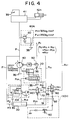
- Fig. 4 is a diagram illustrating an embodiment in accordance with a first aspect of the present invention.
- Fig. 4 is a hydraulic circuit diagram of a hydraulic excavator in which the embodiment is incorporated.
- Fig. 1 referred to in the background of the invention is used as it is in Fig. 4, in which the embodiment is added.
- the explanation given with reference to Figs. 2 and 3 used in the description of the background of the invention can also apply correspondingly to this embodiment.
- the arrangement, operation, and advantages which have already been described in the background of the invention are omitted as practically as possible, to avoid a redundant explanation.
- hydraulic pressure, pneumatic pressure, or the like can be used as the pilot signal, as described above, but in this embodiment a hydraulic pilot signal is used.
- the solenoid valves 70, 80 are set to open positions.
- the pilot pressure Pc1 acts on the variable relief valve 60A via the solenoid valve 80 and the pilot circuit Pc7.
- the pilot pressure Pc7 increases the urging force of the spring of the variable relief valve 60A, and increases the relief pressure from 325 kg/cm2 to 350 kg/cm2 (bars).
- the pilot pressure Pc1 acts on the urging force of the spring of the cut-off control valve 10A via the pilot circuit Pc6 and the solenoid valve 70 to maintain the power constant characteristic C to the new relief pressure side.
- the power and speed can be obtained by simply pressing the switch 90.
- a timer is used for the electric circuit (X01) shown in the above-described embodiment in accordance with the first aspect of the invention.
- the two solenoid valves 70, 80 are actuated simultaneously.
- the pressure is boosted by the variable relief valve 60A before the cut-off control is canceled.
- the relief pressure is boosted first. Consequently, there are apprehensions that damage may be caused to the cut-off control valve 10A and other hydraulic devices.
- variable cut-off control valve 10A can be operated in advance of the variable relief valve 60 A so as to eliminate such apprehensions.
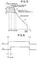
- a timer which is suitable for this function will be described with reference to Fig. 6.
- a time lagged-type timer is desirable when the switch 90 is ON.
- Fig. 7 is a diagram illustrating an embodiment (X02). This is an embodiment in which the timer TB, performing a delaying operation when the switch 90 is turned ON, is mounted in the electric circuit 92.
- the hydraulic control system for a hydraulic excavator in accordance with the present invention is particularly suited to a hydraulic excavator for which heavy-load operations are required.
Landscapes
- Engineering & Computer Science (AREA)
- General Engineering & Computer Science (AREA)
- Mining & Mineral Resources (AREA)
- Civil Engineering (AREA)
- Structural Engineering (AREA)
- Mechanical Engineering (AREA)
- Physics & Mathematics (AREA)
- Fluid Mechanics (AREA)
- Operation Control Of Excavators (AREA)
- Fluid-Pressure Circuits (AREA)
Applications Claiming Priority (3)
| Application Number | Priority Date | Filing Date | Title |
|---|---|---|---|
| JP42904/88 | 1988-02-25 | ||
| JP63042904A JPH01220706A (ja) | 1988-02-25 | 1988-02-25 | 油圧式掘削機の油圧制御装置 |
| PCT/JP1989/000140 WO1989008190A1 (fr) | 1988-02-25 | 1989-02-13 | Unite de commande hydraulique pour excavateurs hydrauliques |
Publications (3)
| Publication Number | Publication Date |
|---|---|
| EP0372081A1 EP0372081A1 (en) | 1990-06-13 |
| EP0372081A4 EP0372081A4 (enExample) | 1994-03-16 |
| EP0372081B1 true EP0372081B1 (en) | 1995-08-23 |
Family
ID=12649020
Family Applications (1)
| Application Number | Title | Priority Date | Filing Date |
|---|---|---|---|
| EP89902300A Expired - Lifetime EP0372081B1 (en) | 1988-02-25 | 1989-02-13 | Hydraulic control unit of hydraulic excavators |
Country Status (6)
| Country | Link |
|---|---|
| US (1) | US5077974A (enExample) |
| EP (1) | EP0372081B1 (enExample) |
| JP (1) | JPH01220706A (enExample) |
| KR (1) | KR0141982B1 (enExample) |
| DE (1) | DE68923934T2 (enExample) |
| WO (1) | WO1989008190A1 (enExample) |
Families Citing this family (15)
| Publication number | Priority date | Publication date | Assignee | Title |
|---|---|---|---|---|
| JPH07103593B2 (ja) * | 1990-06-06 | 1995-11-08 | 株式会社小松製作所 | 積み込み作業車両の制御装置及び方法 |
| JPH04121503U (ja) * | 1991-04-16 | 1992-10-30 | 住友建機株式会社 | 油圧式建設車両の自動昇圧回路 |
| US5456077A (en) * | 1994-04-22 | 1995-10-10 | Mcneilus Truck And Manufacturing, Inc. | Remote unloader hydraulic valve system |
| US5540049A (en) * | 1995-08-01 | 1996-07-30 | Caterpillar Inc. | Control system and method for a hydraulic actuator with velocity and force modulation control |
| JP4026969B2 (ja) * | 1999-01-22 | 2007-12-26 | 株式会社小松製作所 | 建設機械の油圧回路 |
| US6408676B1 (en) | 1999-03-31 | 2002-06-25 | Caterpillar Inc. | Method and apparatus for determining the status of a relief valve |
| KR100797315B1 (ko) * | 2001-07-16 | 2008-01-23 | 두산인프라코어 주식회사 | 굴삭기의 주행 및 프론트작업의 복합작업용 유압제어장치 |
| KR100594851B1 (ko) * | 2002-04-30 | 2006-07-03 | 볼보 컨스트럭션 이키프먼트 홀딩 스웨덴 에이비 | 유압식 브레이크장치 |
| JP4082935B2 (ja) * | 2002-06-05 | 2008-04-30 | 株式会社小松製作所 | ハイブリッド式建設機械 |
| KR100988429B1 (ko) * | 2003-12-26 | 2010-10-18 | 두산인프라코어 주식회사 | 굴삭기의 주행복합작업용 유압제어장치 |
| KR100988443B1 (ko) * | 2003-12-26 | 2010-10-18 | 두산인프라코어 주식회사 | 굴삭기의 주행 및 프론트작업의 복합동작용 유압제어장치 |
| EP1676963A3 (en) * | 2004-12-30 | 2008-12-31 | Doosan Infracore Co., Ltd. | Fluid pump control system for excavators |
| US9086143B2 (en) | 2010-11-23 | 2015-07-21 | Caterpillar Inc. | Hydraulic fan circuit having energy recovery |
| CN102140807B (zh) * | 2011-01-11 | 2012-05-23 | 徐州徐工挖掘机械有限公司 | 一种提高挖掘机挖掘操纵特性和平整作业特性的方法 |
| CN103352886B (zh) * | 2013-06-28 | 2015-12-23 | 山河智能装备股份有限公司 | 能量回收利用液压控制阀 |
Family Cites Families (16)
| Publication number | Priority date | Publication date | Assignee | Title |
|---|---|---|---|---|
| BE757640A (fr) * | 1969-10-16 | 1971-04-16 | Borg Warner | Systemes hydrauliques, notamment pour la regulation d'une pompea debit variable |
| JPS5217795Y2 (enExample) * | 1971-04-26 | 1977-04-22 | ||
| JPS54126146U (enExample) * | 1978-02-22 | 1979-09-03 | ||
| DE3024399A1 (de) * | 1980-06-28 | 1982-01-21 | Linde Ag, 6200 Wiesbaden | Regeleinrichtung fuer ein aggregat aus mehreren, von einer gemeinsamen primaerenergiequelle angetriebenen pumpe |
| US4571941A (en) * | 1980-12-27 | 1986-02-25 | Hitachi Construction Machinery Co, Ltd. | Hydraulic power system |
| JPS57184749A (en) * | 1981-05-01 | 1982-11-13 | Hitachi Constr Mach Co Ltd | Control device for hydraulic system |
| JPS5876853U (ja) * | 1981-11-19 | 1983-05-24 | 株式会社小松製作所 | 油圧駆動装置 |
| US4481770A (en) * | 1982-03-22 | 1984-11-13 | Caterpillar Tractor Co. | Fluid system with flow compensated torque control |
| JPH0633772B2 (ja) * | 1983-12-29 | 1994-05-02 | カヤバ工業株式会社 | 可変容量ポンプの制御装置 |
| JPS60250132A (ja) * | 1984-05-25 | 1985-12-10 | Kayaba Ind Co Ltd | 建設車両の油圧制御回路 |
| JPS6193552A (ja) * | 1984-10-15 | 1986-05-12 | Matsushita Electric Works Ltd | 充電式電気機器 |
| JPS6193552U (enExample) * | 1984-11-27 | 1986-06-17 | ||
| JPS6256801A (ja) * | 1985-09-06 | 1987-03-12 | Toshiba Corp | 曲り導体のピツチ間距離測定器 |
| JPS6256801U (enExample) * | 1985-09-30 | 1987-04-08 | ||
| JPS62167880A (ja) * | 1986-01-20 | 1987-07-24 | Nippon Kokan Kk <Nkk> | 管内外面のコ−テイング装置 |
| JPH0740702Y2 (ja) * | 1986-04-11 | 1995-09-20 | 株式会社小松製作所 | 移動式建設機械の油圧駆動装置 |
-
1988
- 1988-02-25 JP JP63042904A patent/JPH01220706A/ja active Pending
-
1989
- 1989-02-13 WO PCT/JP1989/000140 patent/WO1989008190A1/ja not_active Ceased
- 1989-02-13 KR KR1019890701117A patent/KR0141982B1/ko not_active Expired - Fee Related
- 1989-02-13 EP EP89902300A patent/EP0372081B1/en not_active Expired - Lifetime
- 1989-02-13 DE DE68923934T patent/DE68923934T2/de not_active Expired - Fee Related
- 1989-02-13 US US07/425,207 patent/US5077974A/en not_active Expired - Fee Related
Also Published As
| Publication number | Publication date |
|---|---|
| KR0141982B1 (ko) | 1999-02-18 |
| JPH01220706A (ja) | 1989-09-04 |
| DE68923934D1 (de) | 1995-09-28 |
| EP0372081A1 (en) | 1990-06-13 |
| KR900700699A (ko) | 1990-08-16 |
| EP0372081A4 (enExample) | 1994-03-16 |
| WO1989008190A1 (fr) | 1989-09-08 |
| DE68923934T2 (de) | 1996-04-11 |
| US5077974A (en) | 1992-01-07 |
Similar Documents
| Publication | Publication Date | Title |
|---|---|---|
| EP0372081B1 (en) | Hydraulic control unit of hydraulic excavators | |
| EP0402474B1 (en) | Service valve circuit in a hydraulic excavator | |
| EP1477686B1 (en) | Hydraulic controller for working machine | |
| US5852934A (en) | Fluid joining device for power construction vehicles | |
| US5862831A (en) | Variable-regeneration directional control valve for construction vehicles | |
| US8146482B2 (en) | Hydraulic circuit having holding valve of external pilot pressure operation type | |
| CN100357531C (zh) | 作业机械的液压控制装置 | |
| US4986072A (en) | Hydraulic actuator circuit with flow-joining control | |
| EP1593855A2 (en) | Hydraulic control valve having holding valve with improved response characteristics | |
| RU2700971C2 (ru) | Гидравлическая система, способ управления и машина, содержащая данную гидравлическую систему | |
| KR100527378B1 (ko) | 붐합류용 스플을 이용한 중장비 옵션장치용 유압회로 | |
| KR100474259B1 (ko) | 건설기계의작업장치용실린더를위한유압장치 | |
| US6612109B2 (en) | Hydraulic power boost system for a work vehicle | |
| KR100226281B1 (ko) | 가변우선장치 | |
| KR20000052452A (ko) | 건설기계의 유압회로 | |
| CA2260684C (en) | Pump enable system and method | |
| KR200153460Y1 (ko) | 중장비의 충격방지용 밸브 온/오프 제어시스템 | |
| KR0138161Y1 (ko) | 작업조건에 따라 액츄에이터의 속도 조정이 가능한 유압회로 | |
| JP3307442B2 (ja) | 負荷感応形油圧回路 | |
| KR100244100B1 (ko) | 중장비의 우선장치 | |
| KR100559230B1 (ko) | 중장비용 가변우선장치 | |
| JPH11210710A (ja) | 作業用機械の油圧制御回路 | |
| JPH04333729A (ja) | 作業車の油圧回路構造 | |
| KR20040057487A (ko) | 건설중장비의 충격저감밸브 | |
| KR0133245B1 (ko) | 굴삭기 붐 · 암의 속도변환장치 |
Legal Events
| Date | Code | Title | Description |
|---|---|---|---|
| PUAI | Public reference made under article 153(3) epc to a published international application that has entered the european phase |
Free format text: ORIGINAL CODE: 0009012 |
|
| 17P | Request for examination filed |
Effective date: 19900213 |
|
| AK | Designated contracting states |
Kind code of ref document: A1 Designated state(s): DE FR GB |
|
| A4 | Supplementary search report drawn up and despatched |
Effective date: 19940126 |
|
| AK | Designated contracting states |
Kind code of ref document: A4 Designated state(s): DE FR GB |
|
| 17Q | First examination report despatched |
Effective date: 19941202 |
|
| GRAA | (expected) grant |
Free format text: ORIGINAL CODE: 0009210 |
|
| AK | Designated contracting states |
Kind code of ref document: B1 Designated state(s): DE FR GB |
|
| ET | Fr: translation filed | ||
| REF | Corresponds to: |
Ref document number: 68923934 Country of ref document: DE Date of ref document: 19950928 |
|
| PGFP | Annual fee paid to national office [announced via postgrant information from national office to epo] |
Ref country code: FR Payment date: 19960125 Year of fee payment: 8 |
|
| PGFP | Annual fee paid to national office [announced via postgrant information from national office to epo] |
Ref country code: GB Payment date: 19960205 Year of fee payment: 8 |
|
| PGFP | Annual fee paid to national office [announced via postgrant information from national office to epo] |
Ref country code: DE Payment date: 19960215 Year of fee payment: 8 |
|
| PLBE | No opposition filed within time limit |
Free format text: ORIGINAL CODE: 0009261 |
|
| STAA | Information on the status of an ep patent application or granted ep patent |
Free format text: STATUS: NO OPPOSITION FILED WITHIN TIME LIMIT |
|
| 26N | No opposition filed | ||
| PG25 | Lapsed in a contracting state [announced via postgrant information from national office to epo] |
Ref country code: GB Effective date: 19970213 |
|
| GBPC | Gb: european patent ceased through non-payment of renewal fee |
Effective date: 19970213 |
|
| PG25 | Lapsed in a contracting state [announced via postgrant information from national office to epo] |
Ref country code: FR Effective date: 19971030 |
|
| PG25 | Lapsed in a contracting state [announced via postgrant information from national office to epo] |
Ref country code: DE Effective date: 19971101 |
|
| REG | Reference to a national code |
Ref country code: FR Ref legal event code: ST |