EP0370369B1 - Käsebruch-Förderanlage - Google Patents
Käsebruch-Förderanlage Download PDFInfo
- Publication number
- EP0370369B1 EP0370369B1 EP19890121083 EP89121083A EP0370369B1 EP 0370369 B1 EP0370369 B1 EP 0370369B1 EP 19890121083 EP19890121083 EP 19890121083 EP 89121083 A EP89121083 A EP 89121083A EP 0370369 B1 EP0370369 B1 EP 0370369B1
- Authority
- EP
- European Patent Office
- Prior art keywords
- pipe
- main
- common
- cleaning
- pipes
- Prior art date
- Legal status (The legal status is an assumption and is not a legal conclusion. Google has not performed a legal analysis and makes no representation as to the accuracy of the status listed.)
- Expired - Lifetime
Links
- 238000004140 cleaning Methods 0.000 claims description 53
- 235000013351 cheese Nutrition 0.000 claims description 5
- 238000010586 diagram Methods 0.000 description 10
- 238000000034 method Methods 0.000 description 4
- 239000005862 Whey Substances 0.000 description 3
- 102000007544 Whey Proteins Human genes 0.000 description 3
- 108010046377 Whey Proteins Proteins 0.000 description 3
- 239000007788 liquid Substances 0.000 description 3
- 239000000203 mixture Substances 0.000 description 3
- 238000010276 construction Methods 0.000 description 1
- 238000011161 development Methods 0.000 description 1
- 230000018109 developmental process Effects 0.000 description 1
- 238000004519 manufacturing process Methods 0.000 description 1
Images


Classifications
-
- A—HUMAN NECESSITIES
- A01—AGRICULTURE; FORESTRY; ANIMAL HUSBANDRY; HUNTING; TRAPPING; FISHING
- A01J—MANUFACTURE OF DAIRY PRODUCTS
- A01J25/00—Cheese-making
- A01J25/08—Devices for removing cheese from basins
-
- B—PERFORMING OPERATIONS; TRANSPORTING
- B65—CONVEYING; PACKING; STORING; HANDLING THIN OR FILAMENTARY MATERIAL
- B65G—TRANSPORT OR STORAGE DEVICES, e.g. CONVEYORS FOR LOADING OR TIPPING, SHOP CONVEYOR SYSTEMS OR PNEUMATIC TUBE CONVEYORS
- B65G53/00—Conveying materials in bulk through troughs, pipes or tubes by floating the materials or by flow of gas, liquid or foam
- B65G53/30—Conveying materials in bulk through pipes or tubes by liquid pressure
Definitions
- the invention relates to a cheese curd conveyor, with a break pump arranged between a processing station and a portioning station, the break pump being designed as a double pump container, with two containers holding the cheese curd, each via a first line with a common product inlet main line and in each case via one second line are connected to a common product outlet main line, each of the containers having a cleaning ball and both cleaning balls being connected to a supply air source via supply air lines and a common supply air main line and leading into the interior of each container an exhaust air line connected to a common main exhaust air line and a main cleaning line via a A secondary line is connected to the exhaust air lines and another secondary line is connected to the supply air lines and the individual lines can be opened and closed via valves.
- Such a cheese curd conveyor system already exists as a generally known prior art, which is used in particular for the gentle transport of the broken whey mixture from the processing troughs to the portioning machine or to the filling station.
- the broken whey mixture runs into the broken conveyor system over a corresponding gradient. Further transport takes place by pressurizing the pressure vessels with compressed air.
- cleaning liquid is pressed into the containers of the fracture pump via the cleaning balls on top; alternately, the cleaning liquid is also passed through the supply and exhaust air valves.
- the present invention has for its object to improve this known break pump of a curd conveyor system so that the pump container as a system can be completely cleaned in one pass by a so-called CIP program, i.e. So-called continuous cleaning (cleaning-in-place) should be feasible.
- the main product inlet line is simultaneously designed as a main cleaning line and is connected to the main exhaust line via the secondary line, which can be closed by a valve, in that the main exhaust line forks into the secondary line, which is connected to the lines leading to the cleaning balls, and into one Secondary line, which leads to the exhaust air lines connected to a further cleaning ball in the containers and that the two lines connected to the common product outlet main line are each connected via a secondary line and a common line to the common product outlet main line, valves and in a valve and a centrifugal pump are arranged in the common line.
- the containers can thus be completely cleaned as a system using a CIP program.
- the pump containers are advantageously equipped with a freely programmable electronic control which meets the specific needs.
- the broken conveyor system according to the invention is equipped with a device which enables remote regulation of the conveying capacity. This advantageously eliminates the previously cumbersome setting and changing of the desired delivery rate, which results in a simplification.
- FIG. 1 shows in perspective a part of a cheese curd conveyor system, with a processing station 1 with troughs not shown in detail and a portioning station 2. Between the processing station 1 and the portioning station 2 there is a break pump 3, this break pump 3 being designed as a double pump container with two, taking up the curd containers 4 and 5.
- the breakage pump 3 is fed via a product main inlet line 8; The product is conveyed to the portioning station 2 via a main product outlet line 11.
- FIG 2 the construction and piping diagram of the two containers 4 and 5 of the breakage pump 3 is shown in more detail.
- the main product inlet line 8 bifurcates into the two lines 6 and 7, in the area of which valves 53 and 54 are arranged. These two lines 6 and 7 lead into containers 4 and 5, respectively.
- the main product outlet line 11 in turn bifurcates into the two lines 9 and 10, in the line diagram of which two valves 52 and 56 are also arranged.
- the cleaning balls 32 and 33 of the containers 4 and 5 are in turn connected via lines 17 and 18 as well as a line 31 and a throttle valve 50 to a common main exhaust line 19, in the diagram of which a valve 55 is arranged.
- a valve 55 is arranged.
- main exhaust air line 19 is in turn connected via a secondary line 22 to the lines 14 and 15 of the cleaning balls 12 and 13.
- ball valves 32 'and 33' are actuated by a common actuator 34.
- the ball valves 35 'and 36' can be actuated via a common actuating device 38 and the ball valves 37 'and 38' via a common actuating device 39.
- the main exhaust air line 19 is connected to the main product supply line 8 via a secondary line 21, within which a valve 30 is arranged.
- the main product inlet line 8 is simultaneously designed as a main cleaning line 20.
- This piping diagram shown in FIG. 2 gives the possibility of continuous cleaning of the respective pipelines and of the containers and of the cleaning balls in the so-called CIP process, without the production having to be interrupted.
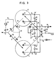
- Figure 3 shows schematically the breakage promotion.
- supply air is fed via the main air supply line 16 'with the ball valve 38' into the secondary line 15, whereby this supply air enters the container 4 via the cleaning ball 13.
- the curd is conveyed via line 9 into the main product outlet line 11 and from there further into the portioning system 2 shown schematically in FIG. 1.
- the container 5 is filled via the main product inlet line 8 and the secondary line 6 with the valve 53 open, while the valve 54 is closed.
- the existing in the container 5 exhaust air is on the cleaning ball 32 with the ball valve 36 'open and on the lines 18 and 31 with the ball valve 32' also open and the throttle 50 transported to the main exhaust pipe 19, the valve 55 being open.
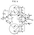
- cleaning medium flows, as shown in dash-dot lines, over the main cleaning line 20, which, as explained above, is also the main product inlet line 8, as well as over the secondary line 6 and the cleaning ball 12 in the container 5, whereby a cleaning of the lines 8 and 20 and the container 5 is made possible.
- This cleaning medium flows from the container 5 via the line 10 with the valve 52 open into the main product outlet line 11, as is also shown in broken lines. Valves 53 and 52 are open and valves 30, 54 and 56 are closed.
- the container 4 and the lines 7 and 9 can be cleaned in a corresponding manner.
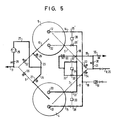
- FIG. 5 shows a further possibility of CIP cleaning: as can be seen, the valve 30 is open here, whereas the valves 53 and 54 are closed. Correspondingly, the cleaning medium flows through the main cleaning line 20 and the lines 21, 19 and 31 with the ball valve 32 'open and the line 17 into the cleaning ball 33 of the container 4. At the same time or alternately, the cleaning medium can flow via the line 18 with open ball valve 36 'get into the cleaning ball 32 of the container 5.
- the cleaning medium can flow via lines 22 and 14 or 15 into the cleaning balls 12 and 13 of the containers 4 and 5. Since the corresponding ball valves 35 'and 36' and 32 'and 33' and 37 'and 38' are each connected in pairs with a corresponding actuating device 34, 38 and 39, the corresponding cleaning process can advantageously be carried out in parallel or alternately.
- the cleaning medium accumulated in the container 4 can flow with the valve 27 open via the lines 24 and 25 to the main product outlet line 11.
- the valve 26 When the valve 26 is open, there is in parallel the possibility that the cleaning medium accumulated in the container 5 also flows via the lines 10, 23 and 25 to the main product outlet line 11.
- the valves 52 and 56 of the lines 9 and 10 are closed, whereas the valve 28 in the line 25 is open.
- the flow pattern of the cleaning medium is shown in the piping diagram according to FIG. 5 in solid lines or in dashed lines or in dash-dotted lines.
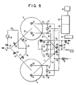
- FIG. 6 it is possible to connect the individual actuating devices 34, 38 and 39 to a pneumatic actuating device 43, which is in turn controlled by an electronic control unit 42, via corresponding lines (not specified).
- this electronic control unit 42 is connected to a remote control device 45.
- a controller 44 can interact with the aforementioned units. This advantageously enables remote regulation of the delivery rate.
- the electronic control unit 42 is freely programmable, but advantageously always a program for the breakage promotion according to FIG. 3 and a Program for different cleaning cycles according to FIGS. 4 and 5 can be provided.
- the invention advantageously allows the two pump containers 4 and 5 and the corresponding pipelines to be completely cleaned as a system using the CIP process, so that the curd conveyor system has a higher overall effectiveness.
- the cleaning medium can be fed back into the circuit via the return line 41, so that the entire system also works efficiently.
Landscapes
- Life Sciences & Earth Sciences (AREA)
- Engineering & Computer Science (AREA)
- Mechanical Engineering (AREA)
- Animal Husbandry (AREA)
- Environmental Sciences (AREA)
- Filling Of Jars Or Cans And Processes For Cleaning And Sealing Jars (AREA)
- Cleaning In General (AREA)
Applications Claiming Priority (2)
| Application Number | Priority Date | Filing Date | Title |
|---|---|---|---|
| DE19883839408 DE3839408C1 (enExample) | 1988-11-22 | 1988-11-22 | |
| DE3839408 | 1988-11-22 |
Publications (2)
| Publication Number | Publication Date |
|---|---|
| EP0370369A1 EP0370369A1 (de) | 1990-05-30 |
| EP0370369B1 true EP0370369B1 (de) | 1991-06-12 |
Family
ID=6367635
Family Applications (1)
| Application Number | Title | Priority Date | Filing Date |
|---|---|---|---|
| EP19890121083 Expired - Lifetime EP0370369B1 (de) | 1988-11-22 | 1989-11-14 | Käsebruch-Förderanlage |
Country Status (3)
| Country | Link |
|---|---|
| EP (1) | EP0370369B1 (enExample) |
| DE (1) | DE3839408C1 (enExample) |
| ES (1) | ES2022744B3 (enExample) |
Family Cites Families (3)
| Publication number | Priority date | Publication date | Assignee | Title |
|---|---|---|---|---|
| NL266814A (enExample) * | 1900-01-01 | |||
| DE1582987A1 (de) * | 1967-07-04 | 1971-08-19 | Conrad Lenz | Einrichtung zur Herstellung von Kaeseformkoerpern aus einem Bruch-Molkegemisch |
| DE3144067A1 (de) * | 1981-11-06 | 1983-05-26 | Ruhrkohle Ag, 4300 Essen | Verfahren zum einschleusen von feststoffen in hydraulische foerdersysteme und doppelbehaelteraufgeber |
-
1988
- 1988-11-22 DE DE19883839408 patent/DE3839408C1/de not_active Expired - Lifetime
-
1989
- 1989-11-14 EP EP19890121083 patent/EP0370369B1/de not_active Expired - Lifetime
- 1989-11-14 ES ES89121083T patent/ES2022744B3/es not_active Expired - Lifetime
Also Published As
| Publication number | Publication date |
|---|---|
| ES2022744B3 (es) | 1991-12-01 |
| EP0370369A1 (de) | 1990-05-30 |
| DE3839408C1 (enExample) | 1990-02-22 |
Similar Documents
| Publication | Publication Date | Title |
|---|---|---|
| DE68905158T2 (de) | Wasch- und reinigungssystem an verpackungsmaschinen. | |
| EP0354359B1 (de) | Spülblock | |
| EP3753877A1 (de) | Saugfördersystem für schüttgut, insbesondere kunststoffgranulat | |
| DE3115125C2 (enExample) | ||
| EP0582955A1 (de) | Vorrichtung zum Dosieren und Abfüllen von flüssigen oder pastösen Produkten, insbesondere zum Abfüllen von sortierten Produkten, wie z. B. Fruchtjoghurt oder dgl., vorzugsweise auf mehrbahnigen Aseptikmaschinen | |
| DE2005548A1 (enExample) | ||
| DE69419013T2 (de) | Abgabeverfahren und vorrichtung | |
| DE3310452A1 (de) | Verfahren und vorrichtung zur automatischen pneumatischen beschickung einer vielzahl von verbrauchsstellen mit pulverfoermigem gut | |
| EP1065948A1 (de) | Anlage zur kontinuierlichen bereitstellung von mindestens zwei unterschiedlichen flüssigen lebensmittelgemischen | |
| DE1555676C3 (de) | Behälterfahrzeug für Schüttgut | |
| EP3519346B1 (de) | Behälterbehandlungsanlage | |
| EP0370369B1 (de) | Käsebruch-Förderanlage | |
| DE3911781A1 (de) | Vorrichtung zum fuellen und reinigen von behaeltern | |
| DE4023841A1 (de) | Einrichtung zur entnahme von gas- und/oder fluessigkeitsproben aus einem sicherheitsbehaelter von kernkraftwerken | |
| DE2353916C2 (de) | Vorrichtung zum Fördern und gleichzeitigen Volumenmessen von Chargen von Flüssigkeiten | |
| DE19502688C1 (de) | Vorrichtung zur Separierung von Gemelken | |
| DE2136328B2 (de) | Vorrichtung zum Beschicken mehrerer Abnahmestellen mit aus Vorratsbehältern pneumatisch gefördertem Schüttgut | |
| AT400995B (de) | Verfahren zur dosierten abgabe von flüssigfutter an mehrere abgabestellen | |
| DE1582980C2 (de) | Vorrichtung zum Foerdern von Milch aus Kannen in einen Sammeltank | |
| DE10161591A1 (de) | Verfahren und Vorrichtung zur automatischen Entleerung und Neubefüllung von Granulattrichtern zur Produktionsumstellung | |
| DE3504107A1 (de) | Hydraulisches dosier- und foerdersystem | |
| DE1295220B (de) | Abmess- und Zuteilvorrichtung fuer die absatzweise Dosierung von schwer foerderbaren Thermoplasten mit hohem Anteil suspendierter Feststoffe oder fuer leicht brechbare bituminoese Emulsionen u. ae., vorzugsweise als Teil einer Mischanlage zur Herstellung bituminoesen Mischgutes | |
| DE69524137T2 (de) | Verteilsystem für flüssige Produkte | |
| DE2806139C2 (de) | Staubfördervorrichtung mit einem Druckbehälter | |
| DE3823791A1 (de) | Verfahren zur gewinnung von fluessigkeitsproben, insbesondere milchproben |
Legal Events
| Date | Code | Title | Description |
|---|---|---|---|
| PUAI | Public reference made under article 153(3) epc to a published international application that has entered the european phase |
Free format text: ORIGINAL CODE: 0009012 |
|
| AK | Designated contracting states |
Kind code of ref document: A1 Designated state(s): ES FR IT |
|
| 17P | Request for examination filed |
Effective date: 19900424 |
|
| 17Q | First examination report despatched |
Effective date: 19901004 |
|
| GRAA | (expected) grant |
Free format text: ORIGINAL CODE: 0009210 |
|
| AK | Designated contracting states |
Kind code of ref document: B1 Designated state(s): ES FR IT |
|
| ITF | It: translation for a ep patent filed | ||
| ET | Fr: translation filed | ||
| PLBE | No opposition filed within time limit |
Free format text: ORIGINAL CODE: 0009261 |
|
| STAA | Information on the status of an ep patent application or granted ep patent |
Free format text: STATUS: NO OPPOSITION FILED WITHIN TIME LIMIT |
|
| 26N | No opposition filed | ||
| PGFP | Annual fee paid to national office [announced via postgrant information from national office to epo] |
Ref country code: ES Payment date: 19961115 Year of fee payment: 8 |
|
| PGFP | Annual fee paid to national office [announced via postgrant information from national office to epo] |
Ref country code: FR Payment date: 19961120 Year of fee payment: 8 |
|
| PG25 | Lapsed in a contracting state [announced via postgrant information from national office to epo] |
Ref country code: ES Free format text: LAPSE BECAUSE OF NON-PAYMENT OF DUE FEES Effective date: 19971115 |
|
| PG25 | Lapsed in a contracting state [announced via postgrant information from national office to epo] |
Ref country code: FR Free format text: THE PATENT HAS BEEN ANNULLED BY A DECISION OF A NATIONAL AUTHORITY Effective date: 19971130 |
|
| REG | Reference to a national code |
Ref country code: FR Ref legal event code: ST |
|
| REG | Reference to a national code |
Ref country code: ES Ref legal event code: FD2A Effective date: 19981212 |
|
| PG25 | Lapsed in a contracting state [announced via postgrant information from national office to epo] |
Ref country code: IT Free format text: LAPSE BECAUSE OF NON-PAYMENT OF DUE FEES;WARNING: LAPSES OF ITALIAN PATENTS WITH EFFECTIVE DATE BEFORE 2007 MAY HAVE OCCURRED AT ANY TIME BEFORE 2007. THE CORRECT EFFECTIVE DATE MAY BE DIFFERENT FROM THE ONE RECORDED. Effective date: 20051114 |