EP0368669A2 - Procédé pour la fabrication de pare-brise - Google Patents
Procédé pour la fabrication de pare-brise Download PDFInfo
- Publication number
- EP0368669A2 EP0368669A2 EP89311645A EP89311645A EP0368669A2 EP 0368669 A2 EP0368669 A2 EP 0368669A2 EP 89311645 A EP89311645 A EP 89311645A EP 89311645 A EP89311645 A EP 89311645A EP 0368669 A2 EP0368669 A2 EP 0368669A2
- Authority
- EP
- European Patent Office
- Prior art keywords
- frame body
- shaped frame
- window plate
- frame member
- window
- Prior art date
- Legal status (The legal status is an assumption and is not a legal conclusion. Google has not performed a legal analysis and makes no representation as to the accuracy of the status listed.)
- Granted
Links
Images


Classifications
-
- B—PERFORMING OPERATIONS; TRANSPORTING
- B29—WORKING OF PLASTICS; WORKING OF SUBSTANCES IN A PLASTIC STATE IN GENERAL
- B29C—SHAPING OR JOINING OF PLASTICS; SHAPING OF MATERIAL IN A PLASTIC STATE, NOT OTHERWISE PROVIDED FOR; AFTER-TREATMENT OF THE SHAPED PRODUCTS, e.g. REPAIRING
- B29C44/00—Shaping by internal pressure generated in the material, e.g. swelling or foaming ; Producing porous or cellular expanded plastics articles
- B29C44/34—Auxiliary operations
- B29C44/3484—Stopping the foaming reaction until the material is heated or re-heated
-
- B—PERFORMING OPERATIONS; TRANSPORTING
- B29—WORKING OF PLASTICS; WORKING OF SUBSTANCES IN A PLASTIC STATE IN GENERAL
- B29C—SHAPING OR JOINING OF PLASTICS; SHAPING OF MATERIAL IN A PLASTIC STATE, NOT OTHERWISE PROVIDED FOR; AFTER-TREATMENT OF THE SHAPED PRODUCTS, e.g. REPAIRING
- B29C35/00—Heating, cooling or curing, e.g. crosslinking or vulcanising; Apparatus therefor
- B29C35/02—Heating or curing, e.g. crosslinking or vulcanizing during moulding, e.g. in a mould
- B29C35/12—Dielectric heating
-
- B—PERFORMING OPERATIONS; TRANSPORTING
- B29—WORKING OF PLASTICS; WORKING OF SUBSTANCES IN A PLASTIC STATE IN GENERAL
- B29C—SHAPING OR JOINING OF PLASTICS; SHAPING OF MATERIAL IN A PLASTIC STATE, NOT OTHERWISE PROVIDED FOR; AFTER-TREATMENT OF THE SHAPED PRODUCTS, e.g. REPAIRING
- B29C63/00—Lining or sheathing, i.e. applying preformed layers or sheathings of plastics; Apparatus therefor
- B29C63/0026—Lining or sheathing, i.e. applying preformed layers or sheathings of plastics; Apparatus therefor an edge face with strip material, e.g. a panel edge
- B29C63/0034—Lining or sheathing, i.e. applying preformed layers or sheathings of plastics; Apparatus therefor an edge face with strip material, e.g. a panel edge the strip material being folded
-
- B—PERFORMING OPERATIONS; TRANSPORTING
- B29—WORKING OF PLASTICS; WORKING OF SUBSTANCES IN A PLASTIC STATE IN GENERAL
- B29C—SHAPING OR JOINING OF PLASTICS; SHAPING OF MATERIAL IN A PLASTIC STATE, NOT OTHERWISE PROVIDED FOR; AFTER-TREATMENT OF THE SHAPED PRODUCTS, e.g. REPAIRING
- B29C70/00—Shaping composites, i.e. plastics material comprising reinforcements, fillers or preformed parts, e.g. inserts
- B29C70/68—Shaping composites, i.e. plastics material comprising reinforcements, fillers or preformed parts, e.g. inserts by incorporating or moulding on preformed parts, e.g. inserts or layers, e.g. foam blocks
- B29C70/74—Moulding material on a relatively small portion of the preformed part, e.g. outsert moulding
- B29C70/76—Moulding on edges or extremities of the preformed part
- B29C70/763—Moulding on edges or extremities of the preformed part the edges being disposed in a substantial flat plane
-
- B—PERFORMING OPERATIONS; TRANSPORTING
- B29—WORKING OF PLASTICS; WORKING OF SUBSTANCES IN A PLASTIC STATE IN GENERAL
- B29C—SHAPING OR JOINING OF PLASTICS; SHAPING OF MATERIAL IN A PLASTIC STATE, NOT OTHERWISE PROVIDED FOR; AFTER-TREATMENT OF THE SHAPED PRODUCTS, e.g. REPAIRING
- B29C70/00—Shaping composites, i.e. plastics material comprising reinforcements, fillers or preformed parts, e.g. inserts
- B29C70/68—Shaping composites, i.e. plastics material comprising reinforcements, fillers or preformed parts, e.g. inserts by incorporating or moulding on preformed parts, e.g. inserts or layers, e.g. foam blocks
- B29C70/84—Shaping composites, i.e. plastics material comprising reinforcements, fillers or preformed parts, e.g. inserts by incorporating or moulding on preformed parts, e.g. inserts or layers, e.g. foam blocks by moulding material on preformed parts to be joined
-
- B—PERFORMING OPERATIONS; TRANSPORTING
- B60—VEHICLES IN GENERAL
- B60J—WINDOWS, WINDSCREENS, NON-FIXED ROOFS, DOORS, OR SIMILAR DEVICES FOR VEHICLES; REMOVABLE EXTERNAL PROTECTIVE COVERINGS SPECIALLY ADAPTED FOR VEHICLES
- B60J1/00—Windows; Windscreens; Accessories therefor
- B60J1/20—Accessories, e.g. wind deflectors, blinds
- B60J1/2002—Wind deflectors specially adapted for preventing soiling, e.g. for side windows
-
- B—PERFORMING OPERATIONS; TRANSPORTING
- B60—VEHICLES IN GENERAL
- B60J—WINDOWS, WINDSCREENS, NON-FIXED ROOFS, DOORS, OR SIMILAR DEVICES FOR VEHICLES; REMOVABLE EXTERNAL PROTECTIVE COVERINGS SPECIALLY ADAPTED FOR VEHICLES
- B60J10/00—Sealing arrangements
- B60J10/20—Sealing arrangements characterised by the shape
- B60J10/21—Sealing arrangements characterised by the shape having corner parts or bends
-
- B—PERFORMING OPERATIONS; TRANSPORTING
- B60—VEHICLES IN GENERAL
- B60J—WINDOWS, WINDSCREENS, NON-FIXED ROOFS, DOORS, OR SIMILAR DEVICES FOR VEHICLES; REMOVABLE EXTERNAL PROTECTIVE COVERINGS SPECIALLY ADAPTED FOR VEHICLES
- B60J10/00—Sealing arrangements
- B60J10/20—Sealing arrangements characterised by the shape
- B60J10/22—Sealing arrangements characterised by the shape having varying cross-section in the longitudinal direction
-
- B—PERFORMING OPERATIONS; TRANSPORTING
- B60—VEHICLES IN GENERAL
- B60J—WINDOWS, WINDSCREENS, NON-FIXED ROOFS, DOORS, OR SIMILAR DEVICES FOR VEHICLES; REMOVABLE EXTERNAL PROTECTIVE COVERINGS SPECIALLY ADAPTED FOR VEHICLES
- B60J10/00—Sealing arrangements
- B60J10/20—Sealing arrangements characterised by the shape
- B60J10/25—Sealing arrangements characterised by the shape characterised by water drainage means
-
- B—PERFORMING OPERATIONS; TRANSPORTING
- B60—VEHICLES IN GENERAL
- B60J—WINDOWS, WINDSCREENS, NON-FIXED ROOFS, DOORS, OR SIMILAR DEVICES FOR VEHICLES; REMOVABLE EXTERNAL PROTECTIVE COVERINGS SPECIALLY ADAPTED FOR VEHICLES
- B60J10/00—Sealing arrangements
- B60J10/70—Sealing arrangements specially adapted for windows or windscreens
-
- B—PERFORMING OPERATIONS; TRANSPORTING
- B60—VEHICLES IN GENERAL
- B60R—VEHICLES, VEHICLE FITTINGS, OR VEHICLE PARTS, NOT OTHERWISE PROVIDED FOR
- B60R13/00—Elements for body-finishing, identifying, or decorating; Arrangements or adaptations for advertising purposes
- B60R13/07—Water drainage or guide means not integral with roof structure
Definitions
- the present invention relates to a method of manufacturing automobile windows including a window plate and a frame member provided integrally therewith.
- Automobile windows wherein a window plate is integrally provided with a frame member is advantageous in that, since it is not necessary to prepare a window molding member as a separate component from the window plate, the number of components and assembly steps can be reduced to realize an improved productivity in the assembly lines of automobile factories.
- window molding members are known, including upper and side segments which are adapted to extend along the upper and side edges of the window plate, respectively, and which are substantially same with and slightly different from each other in cross-section to satisfy both functional and ornamental requirements. More particularly, in case of a front window molding member, the side segments are provided with elongate weirs which prevent rain water on the widow plate from flowing across the side segment onto side windows, by guiding the water to flow along the weir without disturbing the driver's sight through side windows, while the upper segment without the weir realizes a flush outer surface along the upper edge of the window plate. Also, the weir may be provided for the upper segment of a rear window molding member, which is then adapted to guide water on the roof panel to flow along the weir sidewards thereby to preserve the driver's sight through the rear window.
- a method of manufacturing windows for automobiles each including a window plate and a frame member composed essentially of a thermoplastic synthetic resin material formed into a predetermined shape so as to be integral with the window plate along edges thereof, each frame member including at least one guide portion along at least one edge of the window plate, for guiding water to flow along the guide portion, comprising the steps of:
- the guide portion as an integral part of the frame member can be prepared separately from the pre-shaped body, and caused to adhere with the pre-shaped body during the application of the high frequency voltage to the mold.
- the guide portion as an integral part of the frame member can be prepared by forming the pre-shaped frame body to have a longitudinally constant cross-section including cross-sectional portion which corresponds to the guide portion, and by subsequently subjecting the pre-shaped frame body to the removal of material at least locally over a predetermined length corresponding to the regions of the frame member without the guide portion, before the pre-shaped frame body is placed in the mold cavity.
- the window can be manufactured without subjecting the window plate to a high injection pressure, not only the window plate can be prevented from undesirable tendency of damages, but also the method can be carried out using a mold of less complicated and hence less expensive arrangement.
- the heat foamable agent in the thermoplastic synthetic resin material for the pre-shaped frame body is subjected to a substantially uniform expansion within the entire mold cavity, without accompanying local fluctuation of the expansion degree, so that it is possible to prevent the frame member from undesirable local deformation and to thereby manufacture improved automobile windows with a smooth outer surface and a satisfactory uniformity in the appearance or color.
- the window 1 includes a window plate 2 and a window frame member 3 composed of a thermoplastic synthetic resin material which is integral with the window plate 2 and extends along the edges of the window plate 2.
- the frame member 3 includes first and second lip sections 3a, 3b on its outer side, as well as a web section 3c on its rear side.
- the first lip section 3a is adapted to cover a gap between a shoulder portion of an automobile body panel 4 and the edge of the window plate 2, so as to be engageable with the outer surface of the body panel 4.
- the second lip section 3b and the web section 3c are arranged opposite to each other to accommodate the edge of the window plate 2 therebetween; thus, they are in engagement with the outer and rear surfaces of the window plate 2, respectively.
- the window frame member 3 includes side and upper regions 5, 6 extending along the side and upper edges of the window plate 2, respectively.
- the side regions 5 of the window frame member 3 are provided with longitudinal ridges 7.
- the ridge 7 is provided on the upper region 6 of the window frame member 3.
- the window plate 2 has an opaque printed layer 8 along its periphery on its rear surface, and is mounted on a flange 4a of the body panel 4 with an elongate and flexible dam element 9 and an adhesive material 10 therebetween, which are covered by the opaque printed layer 8 so as not to be visible from outside.
- each ridge 7 on the side region 5 of the frame member 3 serves to guide rain water on the window plate 2 to flow along the ridge and to prevent the water from flowing across the frame member 3, thereby to preserve the driver's sight through a neighbouring side window.
- the ridge 7 on the upper region 6 of the frame member 3 is adapted to guide the rain water on the automobile roof panel to flow along the ridge and to prevent the water from flowing across the frame member 3, for preserving the driver's sight through the rear window.
- the upper region 6 of the frame member 3 in the front window and the side regions 5 of the frame member 3 in the rear window, which are not formed with the ridge 7, makes it readily possible to realize a flush outer surface of the automobile body.
- the automobile window shown in Fig. 1 or 2 can be manufactured by a method according to the present invention, of which a first embodiment will be explained below.
- a window plate 2 and a pre-shaped frame body 11 substantially corresponding to the frame member 3.
- the pre-shaped frame body 3 has a cross-section which is dimensionally somewhat smaller than, but geometrically similar to that of the region of the frame member 3 which is not formed with the ridge 7.
- the pre-shaped frame body 11 is formed by extruding appropriate thermoplastic synthetic resin material having a relatively high dielectric loss, such as plasticized polyvinylchloride (PVC) resin, which contains a heat foamable agent.
- PVC plasticized polyvinylchloride
- the extrusion is carried out under such a predetermined temperature condition that the heat foamable agent in the extruded thermoplastic synthetic resin material is maintained in a substantially unfoamed state or in a medium foamed state in which it has not reached an ultimately desired expansion degree.
- the pre-shaped frame body 11 includes first and second lip sections 11a, 11b and a web section 11c which correspond to the first and second lip sections 3a, 3b and the web section 3c of the frame member 3, respectively, as well as an elongate dam section 11d which corresponds to the dam element 9 and is integrally connected to the web section 11c via a strip-like extension 11e.
- the pre-shaped frame body 11 further includes a groove 12 which is defined between the lip section 11b and the web section 11c.
- the groove 12 has bottom edges formed with slits 13 and the width of the groove 12, i.e.
- the distance between the lip section 11b and the web section 11c is slightly greater than the thickness of the window plate 2, so that the edge of the window plate 2 can be readily inserted into the groove 12 by temporarily deflecting the lip and web sections 11b, 11c about the slits 13 to in cease the width of the groove 12.
- layers of a heat activation type synthetic resin material are formed on the inner surfaces of the groove 12 in the pre-shaped frame body 11 synchronously with or after the extrusion thereof, which can be activated when heated above a predetermined temperature, to adhere the pre-shaped frame body 11 with the window plate 2.
- the adhesive material layers may be formed on the front and rear surfaces of the window plate 2.
- the strip-like extension 11e connecting the dam section 11d with the web section 11c is preferably subjected to local removal of the material along its longitudinal regions 14a to leave a desired number of connection bridges 14b.
- the pre-shaped frame body 11 is temporarily secured to the edge of the window plate 2 by an appropriate mechanical means.
- the pre-shaped frame body 11 may be cut into a predetermined length and then secured to the edge of the window plate 2 with the longitudinal ends of the neighbouring pre-shaped frame bodies 11 in abutment with each other.
- an elongate pre-shaped frame body 11 may be used to continuously cover the upper and side edges of the window plate 2 by bending the pre-shaped frame body 11 into the curvature of the corner regions of the window plate 2 without accompanying an undesirable deformation.
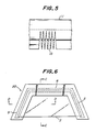
- the elongate pre-shaped frame body 11 may be used to continuously cover the edges of the window plate 2 by forming a series of substantially V-shaped notches 15 (Fig. 5) in those regions of the pre-shaped frame body 11 corresponding to the corner regions of the window plate 2, thereby to facilitate subsequent bending of the pre-shaped frame body 11 into the curvature of the corner regions of the window plate 2.
- the pre-shaped frame body 11 is brought into the cavity of a mold 20 including upper and lower mold halves 21, 22 and having a configuration corresponding to the peripheral contour of the window plate 2.
- the upper mold half 21 is provided with an upper electrode 23 which is held in position by means of a holder plate 24.
- the lower mold half 22 is provided with a lower electrode 25 which is held in position by means of a holder plate 26.
- the two mold halves 21, 22 are tightly engageable with each other along a parting surface 27, to define a mold cavity 28 therebetween.
- the mold halves 21, 22 are composed of a material with a relatively low dielectric loss, such as silicone resin, polyolefin-based resin or appropriate ceramic material.
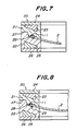
- the electrodes 23, 25 are arranged in the regions of the mold halves 21, 22 corresponding to the frame member 3 on the window plate 2, and shaped to have a width which is greater than the horizontal width of the cavity 28, and spaced from the cavity 28 by as constant distance as possible at any location of the electrodes.
- the cavity 28 of the mold 20 includes side and upper regions connected with each other, which correspond to the side and upper regions 5, 6 of the window frame member 3, respectively.
- each side region of the cavity 28 is formed with a groove 29 for forming the ridge 7 therein.
- the upper mold half 21 is further provided with cutter blades 30 which are adapted to form longitudinal slits in the pre-shaped frame body 11 corresponding to the eventual local removal of its material along the longitudinal regions 14a of the strip-like extension 11e, thereby to leave the connection bridges 14b between the web and dam sections 11c, 11d.
- a filling 31 corresponding to the ridge 7 is arranged in each groove 29 of the mold cavity 28, which preferably consists of a material containing a foamable agent, like the material of the pre-shaped frame body 11.
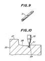
- the filling 31 may be an elongate rod-like body consisting preferably of a thermoplastic synthetic resin material which is same as that of the pre-shaped frame body 11, or which at least exhibits a sufficient compatibility with the latter.
- the rod-like body 31 may be applied with a layer of heat-activation type adhesive material on its surface which is to be opposed to the pre-shaped frame body 11.
- the filling 31 may be in the form of plastic sol or powder discharged from an applicator 32.
- the two mold halves 21, 22 are tightened with each other.
- the electrodes 23, 25 are then applied with high frequency voltage to heat the pre-shaped frame body 11 of a material with a higher dielectric loss, without significantly heating the mold 20 of a material with a lower dielectric loss, or without accompanying softening of the mold 20 or deformation of the cavity 28.
- the pre-shaped frame body 11 is heated to a predetermined temperature above the softening temperature of the resin material and the foamable agent contained in the material of the pre-shaped body 11 is caused to evaporate, inducing the expansion of the entire pre-shaped frame body 11 in the cavity 28 so as to completely fill the inner space of the cavity.
- the adhesive material layer between the pre-shaped frame body 11 and the window plate 2 is activated to integrally connect them with each other, to form a window 1 including a frame member 3 which is integral with the window plate 2.
- the pre-shaped frame body 11 heated above the softening temperature of the resin material is caused to adhere with the filling 31, as shown in Fig. 12, to form a frame member 3 with integral ridges 7.
- the filling 31 contains a foamable agent
- the filling 31 also is caused to expand in the mold cavity 28 to mitigate possible difference in appearance or color between the ridge 7 and the remaining sections of the frame member 3.
- a complete automobile front window 1 in its final form shown in Fig. 1 can be obtained after locally removing material from the frame member 3 along the longitudinal slits formed by the blades 30, leaving the connection bridges 14b between the web section 3c and the dam element 9.
- FIG. 1 or 2 Another embodiment of the method according to the prevent invention for manufacturing the automobile window shown in Fig. 1 or 2 will be explained below.
- This embodiment differs from the previous one in that, instead of forming the ridges 7 by arranging a filling 31 in each groove 29 of the mold cavity 28 and subsequently causing the filling 31 and the pre-shaped frame body 11 to adhere with each other, the pre-shaped frame body 11 is extruded into an initial, longitudinally constant cross-section as shown in Figs. 13a and 13b, including a continuous section 11f with the cross-section of the ridge 7 on the second lip section 11b.
- the pre-shaped frame body 11 is thereafter subjected to a local removal of the continuous section 11f. That is, in case of the automobile front window shown in Fig. 1, the continuous section 11f is removed along the region of the frame body 11 corresponding to the upper region 6 of the frame member 3, while leaving the continuous section 11f along the regions of the frame body 11 corresponding to the side regions 5 of the frame member 3. Similarly, in case of the automobile rear window shown in Fig. 2, the continuous section 11f is removed along the regions of the frame body 11 corresponding to the side regions 5 of the frame member 3, while leaving the continuous section 11f along the region of the frame body 11 corresponding to the upper region 6 of the frame member 3.
- Fig. 14 shows the pre-shaped frame body 11 for an automobile front window, which has been subjected to the local removal of the continuous section 11f and formed with a series of substantially V-shaped notches 15 at regions corresponding to the corner regions of the window plate.
- the above-mentioned step of local removal of the continuous section 11f from the pre-shaped frame body 11, and the step of temporarily securing the frame body 11 to the window plate 2 may be carried out either simultaneously, or one after the other. It is of course that, when placing the pre-shaped frame body 11 in the mold cavity together with the relevant edges of the window plate 2, the remaining region of the continuous section 11f corresponding to the ridge 7 is arranged in the groove 29 within the cavity 28, like the filling 31 as shown in Fig. 11.
- the present embodiment is essentially to carry out the process steps as in the previous one.
- Figs. 15a and 15b differs from that shown in Figs. 1 and 2 in that it includes a channel 41, instead of the ridge 7, as means for guiding the flow of water on the window plate or roof panel.
- the pre-shaped frame body is extruded into the original, longitudinally constant cross-section essentially shown in Fig. 15a, including a longitudinal recess corresponding to the channel 41.
- the recess is locally filled with a synthetic resin material 42 which may contain a foamable agent, along the upper region 6 in case of a front window, or along the side regions 5 in case of the rear window.
- the pre-shaped frame body may be extruded into the original, longitudinally constant cross-section essentially shown in Fig. 15b, including a relatively thick center section at a location corresponding to the channel 41.
- the center section may be subjected to the local removal of the material to form the channel along the side regions 5 in case of a front window, or along the upper region 6 in case of the rear window.
- automobile windows can be manufactured without subjecting the window plate to a high injection pressure, so that the window plate can be prevented from undesirable tendency of damages and the method can be carried out using a mold of less complicated and less expensive arrangement.
- the heat foamable agent in the thermoplastic synthetic resin material for the pre-shaped frame body is subjected to a substantially uniform expansion within the entire mold cavity, without accompanying local fluctuation of the expansion degree, so that it is possible to prevent the frame member from undesirable local deformation and to thereby manufacture improved automobile windows with a smooth outer surface and a satisfactory uniformity in the appearance or color.
- the guide portions in the form of a ridge or channel which are arranged close to the window plate in the above-mentioned embodiments, may be formed at a location which is somewhat remote from the window plate and in the vicinity of the automobile body panel.
Applications Claiming Priority (4)
| Application Number | Priority Date | Filing Date | Title |
|---|---|---|---|
| JP28433688A JPH02128917A (ja) | 1988-11-10 | 1988-11-10 | 合成樹脂枠を有するウインドウの製造方法 |
| JP28433588A JPH02128916A (ja) | 1988-11-10 | 1988-11-10 | 合成樹脂枠を有するウインドウの製造方法 |
| JP284336/88 | 1988-11-10 | ||
| JP284335/88 | 1988-11-10 |
Publications (3)
| Publication Number | Publication Date |
|---|---|
| EP0368669A2 true EP0368669A2 (fr) | 1990-05-16 |
| EP0368669A3 EP0368669A3 (fr) | 1991-07-24 |
| EP0368669B1 EP0368669B1 (fr) | 1994-09-07 |
Family
ID=26555429
Family Applications (1)
| Application Number | Title | Priority Date | Filing Date |
|---|---|---|---|
| EP89311645A Expired - Lifetime EP0368669B1 (fr) | 1988-11-10 | 1989-11-10 | Procédé pour la fabrication de pare-brise |
Country Status (3)
| Country | Link |
|---|---|
| EP (1) | EP0368669B1 (fr) |
| CA (1) | CA2002768C (fr) |
| DE (1) | DE68918050T2 (fr) |
Cited By (9)
| Publication number | Priority date | Publication date | Assignee | Title |
|---|---|---|---|---|
| DE9012288U1 (fr) * | 1990-08-27 | 1991-09-19 | Siv Deutschland Gmbh, 6000 Frankfurt, De | |
| EP0458662A2 (fr) * | 1990-05-18 | 1991-11-27 | Sonoco Products Company | Revêtement en matière plastique pour le bord d'un fût en matière fibreuse |
| EP0485639A1 (fr) * | 1990-11-10 | 1992-05-20 | Kuo-Nan Yang | Procédé de fabrication de semelles intérieur EVA |
| EP0493809A1 (fr) * | 1990-12-29 | 1992-07-08 | Asahi Glass Company Ltd. | Procédé de fabrication d'une vitre avec cadre en matière plastique |
| EP0577195A1 (fr) * | 1992-07-01 | 1994-01-05 | ELELYS S.p.A. | Moule pour le moulage de matières plastiques par l'application d'un champs électromagnétique |
| US6106931A (en) * | 1990-12-27 | 2000-08-22 | Tokai Kogyo Kabushiki Kaisha | Panel unit |
| WO2002066277A3 (fr) * | 2001-02-15 | 2002-10-31 | Ct Luxembourgeois Rech Verre | Procede d'application d'un profil extrude sur des coins de vitre de fenetre |
| FR2947498A1 (fr) * | 2009-07-03 | 2011-01-07 | Peugeot Citroen Automobiles Sa | Enjoliveur de montant de baie de pare-brise comportant une gouttiere pour l'ecoulement de l'eau et vehicule dont les montants de baie sont equipes d'un tel enjoliveur |
| FR2949101A1 (fr) * | 2009-08-11 | 2011-02-18 | Peugeot Citroen Automobiles Sa | Partie avant de vehicule automobile. |
Families Citing this family (2)
| Publication number | Priority date | Publication date | Assignee | Title |
|---|---|---|---|---|
| DE102019126860A1 (de) * | 2019-10-07 | 2021-04-08 | Webasto SE | Deckel zum Verschließen einer Öffnung in einer Fahrzeugkarosserie |
| CN110815899B (zh) * | 2019-10-10 | 2022-01-07 | 中国直升机设计研究所 | 一种直升机桨叶内埋盒形装置及其成型方法 |
Citations (5)
| Publication number | Priority date | Publication date | Assignee | Title |
|---|---|---|---|---|
| GB733623A (en) * | 1952-04-04 | 1955-07-13 | Rubber Improvement Ltd | Improvements in or relating to edge-moulding |
| DE3403518A1 (de) * | 1984-02-02 | 1985-08-14 | Daimler-Benz Ag, 7000 Stuttgart | Ausbildung einer regenrinne eines kraftwagens |
| US4757659A (en) * | 1986-12-04 | 1988-07-19 | Tokiwa Chemical Industries Co., Ltd. | Front glass mouldings |
| DE3707481A1 (de) * | 1987-03-09 | 1988-09-22 | Heinz Schirmacher Gmbh | Fussmatte aus fasermaterial |
| EP0325828A1 (fr) * | 1988-01-29 | 1989-08-02 | Hashimoto Forming Industry Co Ltd | Procédé pour fabriquer des éléments profilés |
-
1989
- 1989-11-10 EP EP89311645A patent/EP0368669B1/fr not_active Expired - Lifetime
- 1989-11-10 CA CA002002768A patent/CA2002768C/fr not_active Expired - Fee Related
- 1989-11-10 DE DE68918050T patent/DE68918050T2/de not_active Expired - Fee Related
Patent Citations (5)
| Publication number | Priority date | Publication date | Assignee | Title |
|---|---|---|---|---|
| GB733623A (en) * | 1952-04-04 | 1955-07-13 | Rubber Improvement Ltd | Improvements in or relating to edge-moulding |
| DE3403518A1 (de) * | 1984-02-02 | 1985-08-14 | Daimler-Benz Ag, 7000 Stuttgart | Ausbildung einer regenrinne eines kraftwagens |
| US4757659A (en) * | 1986-12-04 | 1988-07-19 | Tokiwa Chemical Industries Co., Ltd. | Front glass mouldings |
| DE3707481A1 (de) * | 1987-03-09 | 1988-09-22 | Heinz Schirmacher Gmbh | Fussmatte aus fasermaterial |
| EP0325828A1 (fr) * | 1988-01-29 | 1989-08-02 | Hashimoto Forming Industry Co Ltd | Procédé pour fabriquer des éléments profilés |
Non-Patent Citations (2)
| Title |
|---|
| PATENT ABSTRACTS OF JAPAN, vol. 12, no. 126 (M-687)[2973], 19th April 1988; & JP-A-62 251 229 (TOKAI KOGYO K.K.) 02-11-1987 * |
| PATENT ABSTRACTS OF JAPAN, vol. 13, no. 122 (M-807)[3470], 27th March 1989; & JP-A-63 297 010 (HASHIMOTO FORMING CO., LTD) 05-12-1988 * |
Cited By (15)
| Publication number | Priority date | Publication date | Assignee | Title |
|---|---|---|---|---|
| EP0458662A2 (fr) * | 1990-05-18 | 1991-11-27 | Sonoco Products Company | Revêtement en matière plastique pour le bord d'un fût en matière fibreuse |
| EP0458662A3 (en) * | 1990-05-18 | 1992-04-22 | Sonoco Products Company | Plastic chime overlay for fibre drum |
| DE9012288U1 (fr) * | 1990-08-27 | 1991-09-19 | Siv Deutschland Gmbh, 6000 Frankfurt, De | |
| EP0485639A1 (fr) * | 1990-11-10 | 1992-05-20 | Kuo-Nan Yang | Procédé de fabrication de semelles intérieur EVA |
| US6106931A (en) * | 1990-12-27 | 2000-08-22 | Tokai Kogyo Kabushiki Kaisha | Panel unit |
| US6287406B1 (en) | 1990-12-27 | 2001-09-11 | Tokai Kogyo Kabushiki Kaisha | Methods for making window panel units having in situ extruded frames |
| US6787085B2 (en) | 1990-12-27 | 2004-09-07 | Tokai Kogyo Kabushiki Kaisha | Method for making window panel units having in situ extruded frames |
| US6803001B2 (en) | 1990-12-27 | 2004-10-12 | Tokai Kogyo Kabushiki Kaisha | Method for making window panel units having in situ extruded frames |
| EP0493809A1 (fr) * | 1990-12-29 | 1992-07-08 | Asahi Glass Company Ltd. | Procédé de fabrication d'une vitre avec cadre en matière plastique |
| EP0577195A1 (fr) * | 1992-07-01 | 1994-01-05 | ELELYS S.p.A. | Moule pour le moulage de matières plastiques par l'application d'un champs électromagnétique |
| WO2002066277A3 (fr) * | 2001-02-15 | 2002-10-31 | Ct Luxembourgeois Rech Verre | Procede d'application d'un profil extrude sur des coins de vitre de fenetre |
| US6513854B2 (en) | 2001-02-15 | 2003-02-04 | Centre Luxembourgeois De Recherches Pour Le Verre Et La Ceramique S.A. (C.R.V.C.) | Method of applying extruded profile to corners of a window glazing |
| FR2947498A1 (fr) * | 2009-07-03 | 2011-01-07 | Peugeot Citroen Automobiles Sa | Enjoliveur de montant de baie de pare-brise comportant une gouttiere pour l'ecoulement de l'eau et vehicule dont les montants de baie sont equipes d'un tel enjoliveur |
| FR2949101A1 (fr) * | 2009-08-11 | 2011-02-18 | Peugeot Citroen Automobiles Sa | Partie avant de vehicule automobile. |
| WO2011018570A3 (fr) * | 2009-08-11 | 2011-04-21 | Peugeot Citroën Automobiles SA | Partie avant de vehicule automobile. |
Also Published As
| Publication number | Publication date |
|---|---|
| EP0368669B1 (fr) | 1994-09-07 |
| DE68918050T2 (de) | 1995-02-23 |
| DE68918050D1 (de) | 1994-10-13 |
| CA2002768A1 (fr) | 1990-05-10 |
| EP0368669A3 (fr) | 1991-07-24 |
| CA2002768C (fr) | 1997-10-07 |
Similar Documents
| Publication | Publication Date | Title |
|---|---|---|
| US5197243A (en) | Window for automobiles or the like, and method of manufacturing the same | |
| US4778550A (en) | Method for developing a point of one end of an extruded plastic vehicle molding | |
| KR0183983B1 (ko) | 프로필스트립이 제공된 자동차용 창유리 및 그 제조방법과 장치 | |
| EP0368669B1 (fr) | Procédé pour la fabrication de pare-brise | |
| EP0325828B1 (fr) | Procédé pour fabriquer des éléments profilés | |
| US5028460A (en) | Molding member and method of producing same | |
| FI103493B (fi) | Menetelmä lasiruudulle pursotetun profiilin parantamiseksi ja/tai uusi miseksi | |
| US4555607A (en) | Process for installation and removal of glass pane from a frame | |
| ES277280U (es) | Cabezal de extrusion para extruir tiras aislantes de material elastomerico | |
| GB2235152A (en) | Improvements in and relating to vehicle trim strips having remoulded ends and methods and apparatus for forming them | |
| US5435865A (en) | Process for manufacturing an automotive trim piece having a polymeric skin mounted to a substrate | |
| US5494630A (en) | Method of forming molding end | |
| JPH085092B2 (ja) | ウエザストリップの製造方法 | |
| EP0368441B1 (fr) | Moulure décorative pour véhicules | |
| US6223497B1 (en) | Windows for automobiles and the like | |
| JPH09123213A (ja) | エラストマからなるプロファイルフレームを備える窓ガラスを製造する方法 | |
| JP4104703B2 (ja) | 物体上に押出し成形される特定断面を持つ帯状物を後成形するための成形型 | |
| EP0329048A1 (fr) | Garniture de glissement et d'étanchéité pour glaces coulissantes et rétractables notamment pour véhicules automobiles et méthode de sa fabrication | |
| JP2596096B2 (ja) | ウインドウモールディングおよびその製造方法 | |
| JPS638021A (ja) | ウインドウモ−ルデイングの製造方法 | |
| JP2531218B2 (ja) | 車両用ウインドウの製造方法 | |
| JP2580890B2 (ja) | 剛性の異なる押出体の模様付け型接続方法 | |
| JPH1170544A (ja) | 自動車用ウエザストリップの製造方法 | |
| JP3186497B2 (ja) | 自動車用ウエザストリップおよびその製造方法 | |
| JPH02128916A (ja) | 合成樹脂枠を有するウインドウの製造方法 |
Legal Events
| Date | Code | Title | Description |
|---|---|---|---|
| PUAI | Public reference made under article 153(3) epc to a published international application that has entered the european phase |
Free format text: ORIGINAL CODE: 0009012 |
|
| AK | Designated contracting states |
Kind code of ref document: A2 Designated state(s): DE FR GB IT |
|
| PUAL | Search report despatched |
Free format text: ORIGINAL CODE: 0009013 |
|
| AK | Designated contracting states |
Kind code of ref document: A3 Designated state(s): DE FR GB IT |
|
| 17P | Request for examination filed |
Effective date: 19911106 |
|
| 17Q | First examination report despatched |
Effective date: 19921006 |
|
| GRAA | (expected) grant |
Free format text: ORIGINAL CODE: 0009210 |
|
| AK | Designated contracting states |
Kind code of ref document: B1 Designated state(s): DE FR GB IT |
|
| REF | Corresponds to: |
Ref document number: 68918050 Country of ref document: DE Date of ref document: 19941013 |
|
| ITF | It: translation for a ep patent filed |
Owner name: PROPRIA PROTEZIONE PROPR. IND. |
|
| ET | Fr: translation filed | ||
| PLBE | No opposition filed within time limit |
Free format text: ORIGINAL CODE: 0009261 |
|
| STAA | Information on the status of an ep patent application or granted ep patent |
Free format text: STATUS: NO OPPOSITION FILED WITHIN TIME LIMIT |
|
| 26N | No opposition filed | ||
| PGFP | Annual fee paid to national office [announced via postgrant information from national office to epo] |
Ref country code: GB Payment date: 19961101 Year of fee payment: 8 |
|
| PGFP | Annual fee paid to national office [announced via postgrant information from national office to epo] |
Ref country code: FR Payment date: 19961111 Year of fee payment: 8 |
|
| PGFP | Annual fee paid to national office [announced via postgrant information from national office to epo] |
Ref country code: DE Payment date: 19961115 Year of fee payment: 8 |
|
| PG25 | Lapsed in a contracting state [announced via postgrant information from national office to epo] |
Ref country code: GB Free format text: LAPSE BECAUSE OF NON-PAYMENT OF DUE FEES Effective date: 19971110 |
|
| PG25 | Lapsed in a contracting state [announced via postgrant information from national office to epo] |
Ref country code: FR Free format text: THE PATENT HAS BEEN ANNULLED BY A DECISION OF A NATIONAL AUTHORITY Effective date: 19971130 |
|
| GBPC | Gb: european patent ceased through non-payment of renewal fee |
Effective date: 19971110 |
|
| PG25 | Lapsed in a contracting state [announced via postgrant information from national office to epo] |
Ref country code: DE Free format text: LAPSE BECAUSE OF NON-PAYMENT OF DUE FEES Effective date: 19980801 |
|
| REG | Reference to a national code |
Ref country code: FR Ref legal event code: ST |
|
| PG25 | Lapsed in a contracting state [announced via postgrant information from national office to epo] |
Ref country code: IT Free format text: LAPSE BECAUSE OF NON-PAYMENT OF DUE FEES Effective date: 20051110 |