EP0368643A2 - Aufzeichnungsvorrichtung - Google Patents
Aufzeichnungsvorrichtung Download PDFInfo
- Publication number
- EP0368643A2 EP0368643A2 EP89311568A EP89311568A EP0368643A2 EP 0368643 A2 EP0368643 A2 EP 0368643A2 EP 89311568 A EP89311568 A EP 89311568A EP 89311568 A EP89311568 A EP 89311568A EP 0368643 A2 EP0368643 A2 EP 0368643A2
- Authority
- EP
- European Patent Office
- Prior art keywords
- recording
- paper sheet
- recording paper
- carrying means
- carrying
- Prior art date
- Legal status (The legal status is an assumption and is not a legal conclusion. Google has not performed a legal analysis and makes no representation as to the accuracy of the status listed.)
- Granted
Links
Images


Classifications
-
- B—PERFORMING OPERATIONS; TRANSPORTING
- B41—PRINTING; LINING MACHINES; TYPEWRITERS; STAMPS
- B41J—TYPEWRITERS; SELECTIVE PRINTING MECHANISMS, i.e. MECHANISMS PRINTING OTHERWISE THAN FROM A FORME; CORRECTION OF TYPOGRAPHICAL ERRORS
- B41J13/00—Devices or arrangements of selective printing mechanisms, e.g. ink-jet printers or thermal printers, specially adapted for supporting or handling copy material in short lengths, e.g. sheets
- B41J13/10—Sheet holders, retainers, movable guides, or stationary guides
- B41J13/22—Clamps or grippers
- B41J13/223—Clamps or grippers on rotatable drums
Definitions
- the present invention relates to a recording apparatus for producing hard copies for video systems, computers or the like.
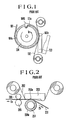
- a recording apparatus according to a first type conveying system of a prior art is shown in Fig. 1.
- a drum 104 having an elastic surface 104a is rotated in a direction indicated with an arrow 1a, while the leading edge 101a of a recording paper sheet 101 is gripped by a gripping device 104b and the recording paper sheet is wound around the drum 104.
- an image of the first colour is recorded in such a manner that heat generating elements 103a of a thermal head 103, which makes pressure-contact with the drum 104 with an ink sheet 102 and a recording paper sheet 101 interposed therebetween, are selectively energized for thermal printing.
- images of the second colour and third colour are sequentially recorded on the same section of the recording paper sheet during the succeeding two revolutions of the drum 104 for completing a full-colour recording of one picture.
- FIG. 2 A recording paper sheet 201 is reciprocally conveyed by means of a driving capstan roller 205 rotatable in both rotating directions and a pinch roller 206 in pressure contact with the capstan roller with the recording paper sheet holded therebetween.
- heat generating elements 203a are selectively energized or controlled in its heat amount, thereby producing a picture having a first colour of the ink sheet 202.
- the thermal head 203 is separated from the platen roller 204 and the capstan roller 205 is rotated in the reverse direction, returning the recording paper sheet 201 in a direction indicated with an arrow 2b to the same position as before recording. Then, the thermal head 203 is again pressed against the platen roller 204, and as conveying the recording paper sheet 201 in a direction indicated with an arrow 2a, an image of a second colour is recorded on the recording paper sheet which have been already recording with the image of the first colour. In a similar way, an image of a third colour is recorded on the recording paper sheet already recorded with the first and second colours, thereby completing a recording of a full-coloured picture.
- the recording paper sheet 201 is conveyed by means of the rigid capstan roller 205, the convey speed of the recording paper sheet 201 is relatively stable. As a result, a fine picture having decreased slippage among three colours can be obtained.
- the recording apparatus of prior art include the following problems.
- the peripheral speed v′ of the drum 104 measured at the pressure contact portion of the thermal head 103 is greater than the speed v measured at non-contact portion of the drum including the portion occupied by the gripping device 104. Accordingly, the conveying speed of the recording paper sheet is dependent upon the peripheral speed v′ at the pressure contact portion.
- the peripheral speed v′ at the pressure contact portion is unstable, and considerably varies depending upon the elasticity of the elastic body 104a or the contact pressure of the thermal head 103. In consequence, the conveying speed of the recording paper sheet can not be maintained at a precisely constant value, thereby casing an irregular density of the recording or positional slippage among the three colour images in recording, resulting in deterioration of picture quality.
- the recording paper sheet 201 is reciprocally conveyed. Therefore, there are required a rather longer return time of the recording paper sheet and the repetitions of contact and separation if the thermal head 203, causing a problem of a longer recording time.
- the present invention is devised and accordingly, the object of the present invention is to provide a recording apparatus in which a multi-coloured image of a high quality having little slippage among three colours can be recorded in a shorter time, and the size of the apparatus can be easily decreased.
- a first measure of the present invention is characterized in that a conveying means rotationally conveys a recording paper sheet around a roller-like rotatable carrier body having an elastic surface, gripping a leading edge of the recording paper sheet, while a recording means is maintained in pressure contact with the carrier body with the paper sheet being interposed therebetween.
- the carrier body is moved following the running motion of the recording paper sheet at the pressure contact portion, and therefor, the recording paper sheet is conveyed only by the driving force of the conveying means which grips the leading edge of the recording paper sheet.
- the conveying speed is maintained with a high degree of precision, resulting in an excellent picture having little slippage among colours and a little irregularity in density of recording. Further, since the recording paper sheet is rotationally conveyed around the carrier body with its leading edge being gripped by the conveying means, the return time of the recording paper sheet is shortened, resulting in a shorter recording time.
- the second measure of the present invention is characterized in that a conveying means rotationally conveys a recording paper sheet around a roller-like stationary carrier body, the surface of which is composed of a rigid surface and an elastic surface, gripping the leading edge of the recording paper sheet, while a recording means is made in pressure contact with the elastic surface of the carrier body for recording.
- the recording paper sheet is conveyed only by the driving force of the conveying device gripping the leading edge of the recording paper sheet, even in such case that the friction between the recording paper sheet and the carrier body becomes greater due to the stationary state of the carrier body.
- the carrier body since the most portion of the carrier body is rigid, variations in the length of the running path of the recording paper sheet along the surface of the carrier body is decreased, and accordingly, the recording paper sheet is conveyed with a more precise speed and a more excellent picture can be obtained in comparison with the conveying apparatus in the first measure.
- the third measure of the present invention is characterized in that a conveying means rotationally conveys a recording paper sheet around a roller-like stationary and rigid carrier body gripping the leading edge of the recording paper sheet, while a recording means is made in pressure contact with a rotatable elastic roller, which is disposed inside of the carrier body and constitutes a part of the outer peripheral surface of the carrier body.
- a means which is made in pressure contact with the recording device is a rotatable roller, the load on the recording paper sheet at the recording portion is decreased, and the driving force for driving the conveying means can be also decreased.
- the fourth measure of the present invention is characterized in that a conveying means rotationally conveys a recording paper sheet around a stationary and rigid carrier body of an elliptic shape, gripping the leading edge of the recording paper sheet, while a recording means is made in pressure contact with a rotatable elastic roller, which is disposed inside of the carrier body and constitutes a part of the outer surface of the carrier body, for recording.
- a conveying means rotationally conveys a recording paper sheet around a stationary and rigid carrier body of an elliptic shape, gripping the leading edge of the recording paper sheet, while a recording means is made in pressure contact with a rotatable elastic roller, which is disposed inside of the carrier body and constitutes a part of the outer surface of the carrier body, for recording.
- the fifth measure of the present invention is characterized in that a conveying means rotationally conveys a recording paper sheet around a stationary and rigid carrier body of an elliptic shape, gripping the leading edge of the recording paper sheet, while a rotatable elastic roller is made in pressure contact with a recording means, which is disposed in the carrier body and constitutes a part of the outer surface of the carrier body, for recording.
- a conveying means rotationally conveys a recording paper sheet around a stationary and rigid carrier body of an elliptic shape, gripping the leading edge of the recording paper sheet, while a rotatable elastic roller is made in pressure contact with a recording means, which is disposed in the carrier body and constitutes a part of the outer surface of the carrier body, for recording.
- FIG. 3 is a basic illustration of a recording apparatus according to a first embodiment of the present invention
- Fig. 4 is an enlarged perspective view showing an ink sheet 2 which is one of the constituent members in Fig. 3
- Fig. 5 is a partly sectional fragmentary schematic illustration showing the behavior of the constituent members shown in Fig. 3.
- a recording paper sheet 1 an ink sheet 2
- a roller-like drum (carrier body) 4 which has a surface layer of an elastic body 4a made of rubber or the like and is rotatably supported by a shaft 4b.
- Numeral 5 denotes a conveying mechanism which perform a predetermined rotary motion about the shaft 4b driven by a driving means not shown with the chuch 5a thereof gripping the front edge 1a of the recording paper sheet 1 with sufficient force. Further, there are shown rotatable guide rollers 6 and 7 which are in pressure contact with the drum 4, guiding the recording paper sheet 1, a sheet supply reel 8 which is wound thereon with an ink sheet 2, a take-up reel 9 for taking up the used ink sheet, and a sheet sensor 10 for detecting a position of the ink sheet 2.
- Fig. 4 shows the ink sheet 2 with respect to its basic structure and its positional relation relative to the sheet sensor 10.
- a transparent basic material 2a on which painted are a yellow ink 2b, a magenta ink 2c and a cyan ink 26 in that order with a predetermined interval, each inked section having an area corresponding to the area of a picture to be recorded.
- Each three inked sections having different three colours, respectively, are defined as one set, and a mark 2e is put for indicating the front of the set.
- the mark 2e is so located in the main scanning direction of the heat generating elements that, when the ink sheet 2 runs in a direction indicated with an arrow (b), the mark 2e passes over a position just opposite to the sheet sensor 10.
- Fig. 5 shows a positional relation between the tip portion 5b of the conveying mechanism 5 and the thermal head 3 at the time when the conveying mechanism 5 passes just over the pressure contact portion 4b of the thermal head.
- the surface of the tip portion 5b has the substantially same property as that of the recording paper sheet.
- the thermal head is made in pressure contact with the drum 4, and the conveying mechanism 5 is rotated in a direction indicated with the arrow (a) by a driving means not shown such as a pulse motor for conveying the recording paper sheet 1 by a predetermined distance.
- the sheet take-up reel 9 is also rotated for conveying the ink sheet 2 in a direction indicated with the arrow (b) and taking up the same with no slack.
- the heat generating elements 3a are selectively energized or controlled in its heat amount for transferring the ink of the ink sheet 2 onto the recording paper sheet 1, thereby completing a recording of the yellow ink over the whole picture area.
- the conveying means 5 has rotated substantially one round around the periphery of the drum 4.
- the conveying mechanism 5 further rotates in a direction indicated with the arrow (a), and passes over the head pressure contact portion 4c while the tip portion 5b pushing the thermal head 3 upwards.
- the ink sheet 2 is continuously conveyed in a direction indicated with the arrow (b).
- the record starting position of the second colour section i.e. the magenta section
- the same operation as for the first colour section is repeated, thereby recording a picture of magenta colour over the picture of yellow colour.
- the drum 4 is driven by a frictional force existing between the head pressure contact portion 4c and the recording paper sheet 1, following the motion of the recording paper sheet 1.
- the recording paper sheet is driven only by the conveying mechanism 5 which rotates with its tip portion gripping the front edge 1a of the recording paper sheet 1, but receives no driving force from the drum 4.
- an elastic body 4a is provided around the outer periphery of the drum 4.
- a film of a low friction material such as Teflon may be attached on the surface of the elastic body 4a, or the elastic body itself may be made of a low friction material.
- Fig. 6 shows a basic arrangement of a recording apparatus according to this second embodiment.
- the drum 14 (carrying means) is stationary and secured to a fixed shaft 14b.
- a conveying mechanism 5 is adapted to rotate around the drum 14 in close vicinity to the peripheral surface of the drum with its chucking portion 5a gripping the leading edge 1a of the recording paper sheet 1.
- only a part of the drum 14 where a thermal head 3 (recording means) is made in pressure contact with the drum 14 is made of an elastic material 14a, but the other remaining part 14c is made of a rigid material such as hard resin or metal.
- the recording function of this second embodiment is similar to that of the first embodiment, excepting that the drum 14 is not rotatable, but stationary, and according the detailed description is omitted.
- the recording paper sheet 1 is driven only by a driving force of the conveying mechanism 5 gripping the leading edge 1a of the recording paper sheet 1, and receives no other driving force, for example, from the drum 14, even in case the friction between the recording paper sheet 1 and the drum 14 is increased due to a greater winding angle of the recording paper sheet around the drum 14.
- the periphery of the drum 14 is composed of a rigid material, the fluctuation of the running path of the recording paper sheet guided along the surface of the drum 14 is decreased.
- the reproducibility of the conveying speed and the conveying distance for the recording paper sheet can be improved, and an excellent picture quality having a little irregularity in density of recording and little positional slipage among colours can be obtained.
- the recording time can be also easily shortened for the same reason as in the first embodiment.
- Fig. 7 is a schematic view showing a basic arrangement of a recording apparatus according to the third embodiment.
- like reference numerals are attached to like elements as those as shown in Fig. 6, and accordingly the detailed description is omitted for the sake of brevity.
- the difference from those shown Fig. 6 is that inside of a stationary rigid drum 24 (conveying mechanism), there is provided a platen roller 25 having a surface layer 25a made of elastic materials such as rubber and being rotatable about a shaft 25b.
- the platen roller is so arranged that a part thereof constitutes a part of the outer peripheral surface of the drum 24 at an opening portion 24a of the drum 24.
- a thermal head 3 (recording means) is in pressure contact with the platen roller 25, an ink sheet 2 and a recording paper sheet 1 being interposed therebetween.
- the recording function of this third embodiment is similar to that of the second embodiment, excepting that the drum 14 is not rotatable, but stationary, and therefore the description thereof is omitted.
- the platen roller 25 rotates only in dependence upon the motion of the recording paper sheet 1. Therefore, the recording paper sheet 1 is conveyed only by the conveying means 5 which rotates with its tip portion gripping a front edge 1a of the recording paper sheet 1, and receives no driving force from the platen roller 25. As a result, the conveying speed of the recording paper sheet is stabilized, and the reproducibility of the conveying distance of the same is improved, resulting in an excellent picture quality having a little irregularity in density and little slippage among-colours.
- the platen roller is rotatable, the load exerted on the conveying mechanism 5 for conveying the recording paper sheet 1 is decreased, and the recording paper sheet is conveyed in a stable manner.
- a recording apparatus of smaller size and lower cost can be obtained.
- the recording time can be easily shortened.
- Fig. 8 is a schematic view showing a basic arrangement of a recording apparatus according to the fourth embodiment.
- like reference numerals are attached to like elements as those shown in Fig. 7, and the detailed description is for the sake of brevity omitted.
- the difference from those shown in Fig. 7 is that a rigid and stationary carrier body 34 has not a roller-like shape, but has an elliptical shape, and a conveying mechanism 15 rotating around the carrier body 34 gripping the leading edge 1a of a recording paper sheet 1 is composed of pulleys 15c, 15d and a belt 15e.
- a platen roller 25 is so arranged that a part of the surface thereof constitutes a part of the preripheral surface of the carrier body 34 at an opening portion 34a of the carrier body 34 which locates at a position where the radius of curvature of the carrier body surface is maximum.
- a thermal head 3 (recording means) is in pressure contact with the platen roller 25, an ink sheet 2 and a recording paper sheet 1 being interposed therebetween.
- the recording function of this fourth embodiment is similar to that of the third embodiment, excepting that the conveying mechanism 15 does not move along a circular path, but is rotated around the surface of a carrier body 34 of an elliptical shape by means of pulleys 15c, 15d and a belt 15e, and therefore the description thereof is omitted.
- an apparatus having a shorter recording time, a high picture quality and a small size and a low cost is obtained for the same reason as in the first to the third embodiments.
- the carrier body 34 has an elliptical shape, the size of the apparatus is further decreased, and since the platen roller 25 is located at an opening portion 34a of the carrier body 34 where the radius of curvature of the carrier body surface is maximum, and the thermal head 3 is pressed on the platen roller 25, the recording paper sheet 1 is heated at a substantially flat region of the recording paper sheet, thereby protecting the recording paper sheet from curling.
- the platen roller is located at a position where the radius of curvature of the elliptic carrier body 34 is maximum, it may be also possible to locate the platen roller at a position where the radius of curvature is minimum. In this modification, the total height of the apparatus including the thermal head is further decreased.
- the frictional resistant force between the recording paper sheet 1 and the carrier body 34 is decreased, thereby also decreasing the load exerted on the conveying mechanism 15.
- Fig. 9 is a schematic view showing a basic arrangement of a recording apparatus according to the fifth embodiment.
- like reference numerals are attached to like elements as those shown in Fig. 8, and the detailed description is omitted for the sake of brevity. The difference from those shown in Fig.
- a carrier body 44 is formed to have an oval shape; a thermal head 13, a sheet supply reel 18, a sheet take-up reel 19 and sheet sensor 11 are arranged inside of the carrier body, especially, the thermal head 13 being stationary and located at a position where its recording surface including heat generating elements 13a constitutes a part of the flat peripheral surface of the carrier body 44; and a platen roller 35 is located outside of the carrier body 44, and adapted to be pressed on and separated from the thermal head 13 with a recording paper sheet 1 and a ink sheet 2 being interposed therebetween.
- the recording function of this fifth embodiment is similar to that of the fourth embodiment, excepting that the recording means including the ink sheet 2 and the thermal head 13 is located inside of the carrier body 44, and the description thereof is omitted here.
- an apparatus having a shorter recording time, a high picture quality of a small size and a low cost without substantial curls can be also obtained for the same reason as in the first, third and fourth embodiments.
- the recording means including the ink sheet 2 and the thermal head 13 is located inside of the carrier body 44, the size of the apparatus is remarkably decreased.
- the platen roller is located at a flat portion of the oval carrier body 44, it may be also possible to locate the platen roller at a circular portion of the same. In this modification, the total height of the apparatus including the platen roller 35 is further decreased.
- the conveying mechanism 15 is driven by means of pulleys and a belt, the same effect can be obtained by using other driving means such as a link mechanism.
- the thermal head 3 itself activily moves to contact on or separate from the ink sheet 2 for permitting the ink sheet to move and locating the same at a predetermined position
- the thermal head 3 is normally maintained in a pressure contact state, and raised and separated from the ink sheet 2 by a force from the carrier body 6 in a rotating state, when the carrier body 5 passes over the position of the thermal head 3.
- the recording means is described as of a thermal printing type, but possibly may be of a thermal sensitivity paper type, an electric current sensitive paper type, or the like.
- the colours for recording are composed of yellow, magenta and cyan in this order, the colours and the order may be different from the above, and number of colours including single hues may be also variable. In these modifications, the above-mentioned various advantages of the present invention can be also obtained.
Landscapes
- Electronic Switches (AREA)
- Handling Of Cut Paper (AREA)
- Handling Of Sheets (AREA)
Applications Claiming Priority (2)
| Application Number | Priority Date | Filing Date | Title |
|---|---|---|---|
| JP63286156A JPH02130169A (ja) | 1988-11-11 | 1988-11-11 | 記録装置 |
| JP286156/88 | 1988-11-11 |
Publications (3)
| Publication Number | Publication Date |
|---|---|
| EP0368643A2 true EP0368643A2 (de) | 1990-05-16 |
| EP0368643A3 EP0368643A3 (en) | 1990-11-07 |
| EP0368643B1 EP0368643B1 (de) | 1995-06-14 |
Family
ID=17700667
Family Applications (1)
| Application Number | Title | Priority Date | Filing Date |
|---|---|---|---|
| EP89311568A Expired - Lifetime EP0368643B1 (de) | 1988-11-11 | 1989-11-08 | Aufzeichnungsvorrichtung |
Country Status (4)
| Country | Link |
|---|---|
| US (1) | US4999649A (de) |
| EP (1) | EP0368643B1 (de) |
| JP (1) | JPH02130169A (de) |
| DE (1) | DE68923059T2 (de) |
Cited By (5)
| Publication number | Priority date | Publication date | Assignee | Title |
|---|---|---|---|---|
| EP0512709A2 (de) * | 1991-04-29 | 1992-11-11 | Tektronix, Inc. | Kompakter Tintenstrahldrucker mit Trommelantrieb |
| DE4220175A1 (de) * | 1991-06-21 | 1992-12-24 | Ricoh Kk | Druckmechanismus fuer einen drucker |
| EP0638432A2 (de) * | 1993-08-12 | 1995-02-15 | Tektronix, Inc. | Rotierende Klammervorrichtung |
| EP0694411A3 (de) * | 1994-07-26 | 1996-11-13 | Mitsubishi Electric Corp | Blattfördergerät |
| EP1588856A1 (de) * | 2003-01-31 | 2005-10-26 | Wedg Co. Ltd | Bildaufzeichnungsvorrichtung |
Families Citing this family (11)
| Publication number | Priority date | Publication date | Assignee | Title |
|---|---|---|---|---|
| JPH03286880A (ja) * | 1990-04-02 | 1991-12-17 | Eastman Kodak Japan Kk | カラープリンタ |
| US5264864A (en) * | 1991-07-22 | 1993-11-23 | Quinton Instrument Company | Chart recorder |
| EP0574332A3 (en) * | 1992-06-09 | 1994-08-17 | Eastman Kodak Co | Thermal printer having a noncontact sensor for determining media type |
| JP2907039B2 (ja) * | 1994-12-22 | 1999-06-21 | 日本ビクター株式会社 | 記録装置 |
| JPH08310069A (ja) * | 1995-05-19 | 1996-11-26 | Minolta Co Ltd | 記録用紙、インクシートの巻き付け方法およびその装置 |
| US5813783A (en) * | 1996-06-24 | 1998-09-29 | Fuji Photo Film Co., Ltd. | Conveying device for a recording paper |
| JPH10138590A (ja) * | 1996-11-07 | 1998-05-26 | Oki Data:Kk | 画像記録装置及び画像入出力装置 |
| EP1095768B1 (de) * | 1999-10-27 | 2004-01-07 | Fuji Photo Film Co., Ltd. | Befestigungsstruktur |
| JP2001246769A (ja) * | 2000-03-03 | 2001-09-11 | Fuji Photo Film Co Ltd | カラーサーマルプリンタ |
| JP4194470B2 (ja) * | 2003-10-30 | 2008-12-10 | キヤノン株式会社 | プリンタ装置およびプリンタの制御方法 |
| JP5005184B2 (ja) * | 2005-04-27 | 2012-08-22 | サントリーホールディングス株式会社 | ラベル貼付装置 |
Citations (4)
| Publication number | Priority date | Publication date | Assignee | Title |
|---|---|---|---|---|
| US4388628A (en) * | 1980-09-01 | 1983-06-14 | Fuji Xerox Co., Ltd. | Multi-color thermal transfer recorder |
| JPS59159370A (ja) * | 1983-03-01 | 1984-09-08 | Matsushita Electric Ind Co Ltd | カラ−プリンタ− |
| JPS59164164A (ja) * | 1983-03-08 | 1984-09-17 | Matsushita Electric Ind Co Ltd | カラ−プリンタ− |
| US4710783A (en) * | 1986-07-24 | 1987-12-01 | Eastman Kodak Company | Temperature compensated continuous tone thermal printer |
Family Cites Families (1)
| Publication number | Priority date | Publication date | Assignee | Title |
|---|---|---|---|---|
| JP2576508B2 (ja) * | 1987-06-11 | 1997-01-29 | 三菱電機株式会社 | サ−マルプリンタ |
-
1988
- 1988-11-11 JP JP63286156A patent/JPH02130169A/ja active Pending
-
1989
- 1989-11-07 US US07/432,868 patent/US4999649A/en not_active Expired - Lifetime
- 1989-11-08 EP EP89311568A patent/EP0368643B1/de not_active Expired - Lifetime
- 1989-11-08 DE DE68923059T patent/DE68923059T2/de not_active Expired - Fee Related
Patent Citations (4)
| Publication number | Priority date | Publication date | Assignee | Title |
|---|---|---|---|---|
| US4388628A (en) * | 1980-09-01 | 1983-06-14 | Fuji Xerox Co., Ltd. | Multi-color thermal transfer recorder |
| JPS59159370A (ja) * | 1983-03-01 | 1984-09-08 | Matsushita Electric Ind Co Ltd | カラ−プリンタ− |
| JPS59164164A (ja) * | 1983-03-08 | 1984-09-17 | Matsushita Electric Ind Co Ltd | カラ−プリンタ− |
| US4710783A (en) * | 1986-07-24 | 1987-12-01 | Eastman Kodak Company | Temperature compensated continuous tone thermal printer |
Non-Patent Citations (2)
| Title |
|---|
| PATENT ABSTRACTS OF JAPAN, vol. 9, no. 11 (M-351)[1734], 18th January 1985; & JP-A-59 159 370 (MATSUSHITA DENKI SANGYO K.K.) 08-09-1984 * |
| PATENT ABSTRACTS OF JAPAN, vol. 9, no. 14 (M-352)[1737], 22nd January 1985; & JP-A-59 164 164 (MATSUSHITA DENKI SANGYO K.K.) 17-09-1984 * |
Cited By (10)
| Publication number | Priority date | Publication date | Assignee | Title |
|---|---|---|---|---|
| EP0512709A2 (de) * | 1991-04-29 | 1992-11-11 | Tektronix, Inc. | Kompakter Tintenstrahldrucker mit Trommelantrieb |
| EP0512709A3 (en) * | 1991-04-29 | 1993-01-20 | Tektronix, Inc. | Compact ink jet printer having a drum drive mechanism |
| DE4220175A1 (de) * | 1991-06-21 | 1992-12-24 | Ricoh Kk | Druckmechanismus fuer einen drucker |
| EP0638432A2 (de) * | 1993-08-12 | 1995-02-15 | Tektronix, Inc. | Rotierende Klammervorrichtung |
| EP0638432A3 (de) * | 1993-08-12 | 1996-01-10 | Tektronix Inc | Rotierende Klammervorrichtung. |
| EP0694411A3 (de) * | 1994-07-26 | 1996-11-13 | Mitsubishi Electric Corp | Blattfördergerät |
| US5609428A (en) * | 1994-07-26 | 1997-03-11 | Mitsubishi Denki Kabushiki Kaisha | Sheet carrying apparatus |
| US5676477A (en) * | 1994-07-26 | 1997-10-14 | Mitsubishi Denki Kabushiki Kaisha | Sheet carrying apparatus |
| EP1588856A1 (de) * | 2003-01-31 | 2005-10-26 | Wedg Co. Ltd | Bildaufzeichnungsvorrichtung |
| EP1588856A4 (de) * | 2003-01-31 | 2008-03-05 | Wedg Co Ltd | Bildaufzeichnungsvorrichtung |
Also Published As
| Publication number | Publication date |
|---|---|
| EP0368643B1 (de) | 1995-06-14 |
| JPH02130169A (ja) | 1990-05-18 |
| DE68923059T2 (de) | 1996-02-01 |
| US4999649A (en) | 1991-03-12 |
| EP0368643A3 (en) | 1990-11-07 |
| DE68923059D1 (de) | 1995-07-20 |
Similar Documents
| Publication | Publication Date | Title |
|---|---|---|
| US4999649A (en) | Sheet conveying device for recording apparatus | |
| US5280308A (en) | Sheet feeding device | |
| CA1300429C (en) | Thermal transcription printer | |
| US4771296A (en) | Transfer ribbon feed arrangement | |
| US4792105A (en) | Film roll mounting assembly | |
| US4547783A (en) | Image forming apparatus | |
| US5215394A (en) | Apparatus for discharging printing paper in a color video printer | |
| US4925324A (en) | Color ink ribbon for thermal printer | |
| US5162816A (en) | Method for setting color of color ink ribbon in thermal transfer printer | |
| US5886727A (en) | Thermal transfer printer and printing method therefor | |
| US5351069A (en) | Sublimation type thermal transfer printer and ink sheet used with the same | |
| US5497182A (en) | Printer having a rotating drum | |
| GB2157235A (en) | Color printer | |
| JP2765131B2 (ja) | 記録装置 | |
| KR100189552B1 (ko) | 칼라 프린터의 캡스턴 롤러 장치 | |
| EP0602283A1 (de) | Thermisches Bildaufzeichnungsgerät mit Tänzerrollervorrichtung zur Aufrechterhaltung der Zugspannung in einem Farbstoffband | |
| US5052831A (en) | Device for exact registration of monochrome images of a color reproduction in a thermal ink transfer printer | |
| KR940007481B1 (ko) | 비디오 프린터의 기록지 홀더장치 | |
| JPH0638686Y2 (ja) | 移動型転写装置 | |
| JPS63115770A (ja) | インクシ−トカセツト | |
| JP3346532B2 (ja) | 転写紙 | |
| JPS5772873A (en) | Color recording apparatus | |
| JPH028775Y2 (de) | ||
| JP2839559B2 (ja) | 印刷装置 | |
| JPS61189974A (ja) | 熱転写プリンタのリボンカ−トリツジ |
Legal Events
| Date | Code | Title | Description |
|---|---|---|---|
| PUAI | Public reference made under article 153(3) epc to a published international application that has entered the european phase |
Free format text: ORIGINAL CODE: 0009012 |
|
| AK | Designated contracting states |
Kind code of ref document: A2 Designated state(s): DE FR GB |
|
| PUAL | Search report despatched |
Free format text: ORIGINAL CODE: 0009013 |
|
| AK | Designated contracting states |
Kind code of ref document: A3 Designated state(s): DE FR GB |
|
| 17P | Request for examination filed |
Effective date: 19901227 |
|
| 17Q | First examination report despatched |
Effective date: 19920804 |
|
| GRAA | (expected) grant |
Free format text: ORIGINAL CODE: 0009210 |
|
| AK | Designated contracting states |
Kind code of ref document: B1 Designated state(s): DE FR GB |
|
| REF | Corresponds to: |
Ref document number: 68923059 Country of ref document: DE Date of ref document: 19950720 |
|
| ET | Fr: translation filed | ||
| PLBE | No opposition filed within time limit |
Free format text: ORIGINAL CODE: 0009261 |
|
| STAA | Information on the status of an ep patent application or granted ep patent |
Free format text: STATUS: NO OPPOSITION FILED WITHIN TIME LIMIT |
|
| 26N | No opposition filed | ||
| REG | Reference to a national code |
Ref country code: GB Ref legal event code: IF02 |
|
| PGFP | Annual fee paid to national office [announced via postgrant information from national office to epo] |
Ref country code: GB Payment date: 20031105 Year of fee payment: 15 |
|
| PGFP | Annual fee paid to national office [announced via postgrant information from national office to epo] |
Ref country code: FR Payment date: 20031110 Year of fee payment: 15 |
|
| PGFP | Annual fee paid to national office [announced via postgrant information from national office to epo] |
Ref country code: DE Payment date: 20031120 Year of fee payment: 15 |
|
| PG25 | Lapsed in a contracting state [announced via postgrant information from national office to epo] |
Ref country code: GB Free format text: LAPSE BECAUSE OF NON-PAYMENT OF DUE FEES Effective date: 20041108 |
|
| PG25 | Lapsed in a contracting state [announced via postgrant information from national office to epo] |
Ref country code: DE Free format text: LAPSE BECAUSE OF NON-PAYMENT OF DUE FEES Effective date: 20050601 |
|
| GBPC | Gb: european patent ceased through non-payment of renewal fee |
Effective date: 20041108 |
|
| PG25 | Lapsed in a contracting state [announced via postgrant information from national office to epo] |
Ref country code: FR Free format text: LAPSE BECAUSE OF NON-PAYMENT OF DUE FEES Effective date: 20050729 |
|
| REG | Reference to a national code |
Ref country code: FR Ref legal event code: ST |