EP0368111A2 - Sorption refrigeration system - Google Patents
Sorption refrigeration system Download PDFInfo
- Publication number
- EP0368111A2 EP0368111A2 EP19890120078 EP89120078A EP0368111A2 EP 0368111 A2 EP0368111 A2 EP 0368111A2 EP 19890120078 EP19890120078 EP 19890120078 EP 89120078 A EP89120078 A EP 89120078A EP 0368111 A2 EP0368111 A2 EP 0368111A2
- Authority
- EP
- European Patent Office
- Prior art keywords
- container
- cooling
- sorption
- cooling system
- working medium
- Prior art date
- Legal status (The legal status is an assumption and is not a legal conclusion. Google has not performed a legal analysis and makes no representation as to the accuracy of the status listed.)
- Granted
Links
Images

Classifications
-
- F—MECHANICAL ENGINEERING; LIGHTING; HEATING; WEAPONS; BLASTING
- F25—REFRIGERATION OR COOLING; COMBINED HEATING AND REFRIGERATION SYSTEMS; HEAT PUMP SYSTEMS; MANUFACTURE OR STORAGE OF ICE; LIQUEFACTION SOLIDIFICATION OF GASES
- F25B—REFRIGERATION MACHINES, PLANTS OR SYSTEMS; COMBINED HEATING AND REFRIGERATION SYSTEMS; HEAT PUMP SYSTEMS
- F25B17/00—Sorption machines, plants or systems, operating intermittently, e.g. absorption or adsorption type
- F25B17/08—Sorption machines, plants or systems, operating intermittently, e.g. absorption or adsorption type the absorbent or adsorbent being a solid, e.g. salt
-
- F—MECHANICAL ENGINEERING; LIGHTING; HEATING; WEAPONS; BLASTING
- F25—REFRIGERATION OR COOLING; COMBINED HEATING AND REFRIGERATION SYSTEMS; HEAT PUMP SYSTEMS; MANUFACTURE OR STORAGE OF ICE; LIQUEFACTION SOLIDIFICATION OF GASES
- F25D—REFRIGERATORS; COLD ROOMS; ICE-BOXES; COOLING OR FREEZING APPARATUS NOT OTHERWISE PROVIDED FOR
- F25D11/00—Self-contained movable devices, e.g. domestic refrigerators
Definitions
- the invention relates to a sorption cooling system comprising a cooling container and an adsorption container.
- compressor cooling units essentially consist of a, mostly hermetically sealed, compressor, a forced-cooled condenser, a collecting container for the liquid refrigerant, a temperature-controlled expansion valve and an evaporator.
- the cold generated in the evaporator must be temporarily stored in a cold buffer, since the evaporator capacity is significantly lower than the cooling capacity required during a dispensing process.
- the compression device has a longer running time than the sum of the individual tapping operations.
- Today's cold buffers either have a water tank with a capacity of up to 20 l or a large aluminum block.
- the biggest disadvantage of the aluminum block is that the storage capacity is relatively small, so that when more than 0.5 l of liquid are drawn, the cooling effect is already exhausted.
- the water storage device has the disadvantage that after filling the water, the device must be in operation for a long time in order to cool the water filling itself.
- the water tank must be provided with an additional agitator, which the water around the evaporator and cooling coils for better heat exchange pumped around. This mechanical agitator is extremely susceptible to failure and therefore often leads to the failure of the entire cooling device.
- Such compression refrigerators are used to cool beverages, e.g. B. beer, lemonades etc. used in marquees or at parties. Your use in the private individual z. B. for cooling a borrowed beer barrel is only possible to a limited extent, since the high complexity of the device requires a lot of technical expertise from the user and the refrigerator cannot be used profitably for the beverage publisher due to the high acquisition or maintenance costs.
- Sorption apparatus is understood to mean devices in which a liquid or solid sorbent sorbs a second, higher-boiling agent, the working fluid sorbs with heat release. Before the working medium is sorbed by sorbent, it evaporates in a cooling container while absorbing heat. The evaporation temperatures range from -40 ° to + 40 ° C, depending on the type of working fluid or the area in which the sorbent is used. Sorption devices with solid adsorbents, so-called adsorption devices work periodically, i. H. A sorption phase is always followed by a desorption phase in which the working fluid is separated from the adsorbent. The working medium cannot be sorbed during the desorption phase and therefore cannot evaporate. There is therefore no cold in the cooling container.
- a periodically operating adsorption cooling apparatus in which an ice bank is built up during the adsorption phase by partial evaporation of the working medium water.
- the apparatus exists thereby from an adsorption container which is filled with the sorbent zeolite, a cooling container which contains the working medium water and from which a vapor channel between the adsorption container and the cooling container can be shut off by means of a shut-off device.
- Cold for example for cooling a cooling bag, can be dissipated via the container surfaces of the cooling container, while heat can be called up via the container walls of the adsorption container.
- the working medium is desorbed from the sorbent by supplying desorption heat to the adsorption container and reliquefied in the cooling container with heat being released.
- the shut-off device is closed and the adsorption container is cooled. In this state, the adsorption apparatus can be stored for any length of time.
- the object of the present invention is to show a sorption cooling system which is characterized by a simple and inexpensive design and with the aid of which larger amounts of liquid can be cooled to temperatures between + 4 ° and + 10 ° C from any initial temperature with little control effort.
- the sorption cooling system consists of a transportable cooling unit and a stationary charging station that can be separated therefrom. With a single charging station, a multitude is more portable Cooling units can be regenerated. In order to keep the cooling units easily transportable, they only consist of the technically absolutely necessary parts, namely an adsorption container filled with an adsorbent, a cooling container that contains the liquid working fluid and a heat exchanger embedded therein, a working fluid vapor channel that connects the adsorption container with the cooling container connects and a shut-off device that makes the steam channel shut off.
- the working fluid When loaded, the working fluid is separated from the adsorbent as a liquid in the cooling container.
- the shut-off device is closed, adsorption and working media are at ambient temperature.
- the cooling unit can be delivered to the customer, e.g. B. can be borrowed together with a beer keg.
- the customer connects the beverage lines to the heat exchanger and opens the shut-off device.
- the working fluid can now evaporate in the cooling container, flow via the working fluid vapor channel to the adsorbent and can be adsorbed by the latter with the release of heat.
- the heat of adsorption is dissipated via the walls of the adsorption container, for example to the ambient air.
- the adsorption container can also advantageously be coupled to a water container, the water content of which can absorb the heat of adsorption.
- the evaporation of the working fluid creates cold in the cooling container, which cools the medium flowing through the heat exchanger, for example a beverage.
- the outlet temperature of the beverage can be regulated by temperature-controlled opening and closing of the shut-off device.
- Zeolite is a crystalline mineral that consists of a regular framework structure made of silicon and aluminum oxides. This scaffold structure contains small cavities in which water molecules can be adsorbed with the release of heat. Within the framework structure, the water molecules are exposed to strong field forces, which liquefy the molecules in the lattice and bind them in a liquid-like phase. The strength of the binding forces acting on the water molecules depends on the amount of water already contained in the structure and the temperature of the zeolite. For practical use, up to 25 grams of water can be adsorbed per 100 grams of zeolite. Zeolites are solid substances without annoying thermal expansion during the adsorption or desorption reaction. The framework structure is freely accessible from all sides for the water vapor molecules. The cooling unit can therefore be used in any position.
- the cooling capacity of the cooling unit is determined by the amount of zeolite filled in and the adsorbent temperature reached at the end of the tap time. This amount can therefore be designed so that one cooling unit is sufficient to cool a complete beverage container (beer keg, lemonade container, etc.).
- the adsorption container After returning the discharged cooling unit, it is placed with the adsorption container in an opening in the heating cabinet of the charging station and desorbed. During this charging process, the adsorbent is heated and the working fluid is evaporated. The vaporous working fluid is re-liquefied in a suitable heat exchanger and returned to the cooling tank. The temperature of the heating cabinet is between 250 ° and 350 ° C at the end of the charging phase. As soon as the adsorbent is heated up and the working fluid is desorbed, the shut-off device is closed and the entire cooling unit is separated from the charging station. The adsorption container can now cool down but cannot draw off any water vapor from the cooling container. The cooling unit can be stored at room temperature until the next use.
- the charging station Since the charging station remains with the respective rental company, it represents only a one-time purchase. All expensive and heavy components, such as electrical heating, temperature control, insulation of the heating cabinet and additional components such as evacuation unit, cooling fan, etc. can be mounted on the charging station.
- the portable cooling unit is therefore light and inexpensive. It therefore does not need its own energy connection for the customer.
- the cooling capacity is immediately available. In addition, it is characterized by a high cooling reserve, so that longer tap operation is possible. After removing the cooling capacity, the cooling unit is worthless to the customer without a separate charging station. He therefore willingly returns them to the lender against reimbursement of his pledge.
- the further heat exchanger of the cooling unit via which the heat of condensation of the working fluid vapor is removed during charging in the charging station, can advantageously be a container wall of the cooling container.
- the charging station can advantageously be equipped with a cooling fan that blows ambient air onto the container wall of the cooling container intended for condensation.
- this heat exchanger is surrounded by the liquid working fluid according to the invention, it must protrude from the liquid working fluid for this purpose. This is achieved, for example, by rotating the cooling container when it is introduced into the heating cabinet to such an extent that the heat exchanger at least partially protrudes from the amount of liquid working fluid. Tap water can flow through the heat exchanger for cooling.
- the shut-off device is required to have a high level of vacuum tightness, particularly when using the pair of zeolite / water substances. Furthermore, the shut-off device be designed so that it opens automatically and allows the working fluid vapor to flow into the cooling container as soon as the vapor pressure in the adsorption container is higher than the vapor pressure in the cooling container. In this way it is ensured that during the desorption phase, if the shut-off device is accidentally closed, no excess pressure can arise in the adsorption container.
- the cooling unit can be equipped with an overpressure safety device.
- a droplet separator can be arranged in the cooling container, which retains droplets of working fluid that arise during the evaporation process.
- the adsorption container is advantageously designed so that desorption heat can be supplied via its container walls in the heating cabinet or the adsorption heat can be removed during the adsorption phase.
- Flat containers which are connected to one another via the working medium steam duct, are particularly suitable for this purpose.
- the amount of adsorbent expediently contains steam channels through which the inflowing working medium is evenly distributed.
- the transportable cooling unit shown in perspective in FIG. 1 consists of six flat adsorption containers 1, which are connected to one another and to the cooling container 3 via a working medium steam channel 2.
- the working medium steam channel 2 can be shut off via a shut-off device 4.
- In the lower part of the cooling container 3 is the inlet and outlet 5.6 to the heat exchanger, not shown.
- Cooling fins 7 are arranged on the outer wall of the cooling container 3 and increase the surface area in order to improve the dissipation of the heat of condensation into the ambient air.
- the stationary charging station is also shown in a perspective view.
- a heating cabinet 8 is provided with an opening 9 in which the adsorption containers 1 of the cooling unit can be accommodated.
- a recess 10 is provided at a corresponding point in the heating cabinet, which allows the lid 11 of the heating cabinet to be closed after the adsorption container 1 has been inserted.
- the cooling container 3 is located via two cooling fans 12, 13, which press ambient air onto the cooling fins 7 of the cooling container.
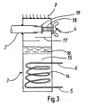
- the cooling container 3 is shown in section.
- a heat exchanger 14 with inlet or outlet 5, 6, embedded in a quantity of water 15.
- a droplet separator 17 is arranged above the ice layer 16.
- a broiled opens into the upper part of the cooling container Chen illustrated working medium steam channel 2.
- the shut-off device 4 consists of a metallic bellows 18 and a flat seal 19 which rests on the mouth of the working medium steam channel 2 in the closed state.
- cooling fins 7 are attached to enlarge the surface.
Abstract
Description
Die Erfindung betrifft ein Sorptionskühlsystem aus einem Kühlbehälter und einem Adsorptionsbehälter.The invention relates to a sorption cooling system comprising a cooling container and an adsorption container.
Auf dem Gebiet der transportablen Getränkekühlung sind bisher nur Kühlgeräte nach dem Kompressionsprinzip im Einsatz. Diese Kompressorkühlgeräte bestehen im wesentlichen aus einem, meist hermetisch gedichteten Kompressor, einem zwangsgekühlten Verflüssiger, einem Sammelbehälter für das flüssige Kältemittel, einem temperaturgeregelten Expansionsventil und einem Verdampfer. Die im Verdampfer erzeugte Kälte muß, da die Verdampferleistung wesentlich kleiner ist als die während eines Zapfvorgangs notwendige Kälteleistung in einem Kältepuffer zwischengespeichert verden. Dadurch erreicht das Kompressionsgerät eine längere Laufzeit als dies der Summe der einzelnen Zapfvorgänge entspricht. Heute übliche Kältepuffer haben entweder einen Wasserbehälter mit bis zu 20 l Inhalt oder einen großen Aluminiumblock. Dieser hat gegenüber dem Wasserbehälter den Vorteil, daß vor Inbetriebnahme des Gerätes kein Wasser eingefüllt werden muß und deshalb das Gerät bereits nach wenigen Minuten betriebsbereit ist. Der größte Nachteil des Aluminiumblockes besteht jedoch darin, daß die Speicherkapazität relativ klein ist, so daß beim Zapfen von mehr als 0,5 l Flüssigkeit bereits die Kühlwirkung erschöpft ist. Der Wasserspeicher hat wiederum den Nachteil, daß nach Einfüllen des Wassers das Gerät längere Zeit in Betrieb sein muß, um die Wasserfüllung selbst abzukühlen. Darüber hinaus muß der Wasserbehälter mit einem zusätzlichen Rührwerk versehen sein, welches das Wasser um die Ver-dampfer- und Kühlschlangen zum besseren Wärmeaustausch umpumpt. Dieses mechanische Rührwerk ist äußerst störanfällig und führt deshalb oft zum Ausfall des ganzen Kühlgerätes.In the field of portable beverage cooling, only cooling devices based on the compression principle have so far been used. These compressor cooling units essentially consist of a, mostly hermetically sealed, compressor, a forced-cooled condenser, a collecting container for the liquid refrigerant, a temperature-controlled expansion valve and an evaporator. The cold generated in the evaporator must be temporarily stored in a cold buffer, since the evaporator capacity is significantly lower than the cooling capacity required during a dispensing process. As a result, the compression device has a longer running time than the sum of the individual tapping operations. Today's cold buffers either have a water tank with a capacity of up to 20 l or a large aluminum block. This has the advantage over the water tank that no water has to be filled in before the device is started up and the device is therefore ready for operation after only a few minutes. The biggest disadvantage of the aluminum block, however, is that the storage capacity is relatively small, so that when more than 0.5 l of liquid are drawn, the cooling effect is already exhausted. The water storage device has the disadvantage that after filling the water, the device must be in operation for a long time in order to cool the water filling itself. In addition, the water tank must be provided with an additional agitator, which the water around the evaporator and cooling coils for better heat exchange pumped around. This mechanical agitator is extremely susceptible to failure and therefore often leads to the failure of the entire cooling device.
Derartige Kompressionskühlgeräte werden zum Kühlen von Getränken, z. B. Bier, Limonaden etc. in Festzelten oder bei Party's eingesetzt. Ihre Verwendung beim Privatmann z. B. zur Kühlung eines geliehenen Bierfasses ist bisher nur beschränkt möglich, da durch die hohe Komplexität des Gerätes beim Anwender viel technischer Sachverstand vorausgesetzt wird und sich für den Getränkeverleger das Kühlgerät aufgrund zu hoher Anschaffungs- bzw. Wartungskosten nicht rentabel einsetzen läßt.Such compression refrigerators are used to cool beverages, e.g. B. beer, lemonades etc. used in marquees or at parties. Your use in the private individual z. B. for cooling a borrowed beer barrel is only possible to a limited extent, since the high complexity of the device requires a lot of technical expertise from the user and the refrigerator cannot be used profitably for the beverage publisher due to the high acquisition or maintenance costs.
Unter Sorptionsapparaten versteht man Geräte, in denen ein flüssiges bzw. festes Sorptionsmittel ein zweites, höher siedenderes Mittel, das Arbeitsmittel unter Wärmefreisetzung sorbiert. Bevor das Arbeitsmittel von Sorptionsmittel sorbiert wird, verdampft es unter Wärmeaufnahme in einem Kühlbehälter. Die Verdampfungstemperaturen liegen dabei, je nach Art des Arbeitsmittels bzw. Einsatzgebiet des Sorptionsmittels, im Bereich zwischen -40° und +40°C. Sorptionsapparate mit festen Adsorptionsmitteln, sog. Adsorptionsapparate arbeiten periodisch, d. h. einer Sorptionsphase folgt immer eine Desorptionphase, in der das Arbeitsmittel wieder vom Adsorptionsmittel getrennt wird. Während der Desorptionsphase kann das Arbeitsmittel nicht sorbiert werden und deshalb auch nicht verdampfen. Im Kühlbehälter entsteht somit auch keine Kälte.Sorption apparatus is understood to mean devices in which a liquid or solid sorbent sorbs a second, higher-boiling agent, the working fluid sorbs with heat release. Before the working medium is sorbed by sorbent, it evaporates in a cooling container while absorbing heat. The evaporation temperatures range from -40 ° to + 40 ° C, depending on the type of working fluid or the area in which the sorbent is used. Sorption devices with solid adsorbents, so-called adsorption devices work periodically, i. H. A sorption phase is always followed by a desorption phase in which the working fluid is separated from the adsorbent. The working medium cannot be sorbed during the desorption phase and therefore cannot evaporate. There is therefore no cold in the cooling container.
Aus der DE-OS 34 25 419 ist ein periodisch arbeitender Adsorptionskühlapparat bekannt, bei welchem während der Adsorptionsphase durch Teilverdampfung des Arbeitsmittels Wasser eine Eisbank aufgebaut wird. Der Apparat besteht dabei aus einem Adsorptionsbehälter, der mit dem Sorptionsmittel Zeolith gefüllt ist, einem Kühlbehälter, der das Arbeitsmittel Wasser enthält und aus einer Absperreinrichtung mit Hilfe derer ein Dampfkanal zwischen dem Adsorptionsbehälter und dem Kühlbehälter absperrbar ist. Über die Behälterflächen des Kühlbehälters kann Kälte, beispielsweise zum Kühlen einer Kühltasche abgeführt werden, während über die Behälterwände des Adsorptionsbehälters Wärme abrufbar ist. Während der Desorptionsphase wird durch Zufuhr von Desorptionswärme in den Adsorptionsbehälter das Arbeitsmittel aus dem Sorptionsmittel desorbiert und im Kühlbehälter unter Wärmeabgabe rückverflüssigt. Nach Abschluß dieses Desorptionsvorganges wird die Absperreinrichtung geschlossen und der Adsorptionsbehälter gekühlt. In diesem Zustand ist der Adsorptionsapparat beliebig lange lagerfähig.From DE-OS 34 25 419 a periodically operating adsorption cooling apparatus is known, in which an ice bank is built up during the adsorption phase by partial evaporation of the working medium water. The apparatus exists thereby from an adsorption container which is filled with the sorbent zeolite, a cooling container which contains the working medium water and from which a vapor channel between the adsorption container and the cooling container can be shut off by means of a shut-off device. Cold, for example for cooling a cooling bag, can be dissipated via the container surfaces of the cooling container, while heat can be called up via the container walls of the adsorption container. During the desorption phase, the working medium is desorbed from the sorbent by supplying desorption heat to the adsorption container and reliquefied in the cooling container with heat being released. After this desorption process is completed, the shut-off device is closed and the adsorption container is cooled. In this state, the adsorption apparatus can be stored for any length of time.
Aufgabe der vorliegenden Erfindung ist es, ein Sorptionskühlsystem aufzuzeigen, das sich durch eine einfache und kostengünstige Bauart auszeichnet und mit dessen Hilfe auch größere Flüssigkeitsmengen auf Temperaturen zwischen +4° und +10°C von einer beliebigen Anfangstemperatur unter geringem Regelaufwand gekühlt werden können.The object of the present invention is to show a sorption cooling system which is characterized by a simple and inexpensive design and with the aid of which larger amounts of liquid can be cooled to temperatures between + 4 ° and + 10 ° C from any initial temperature with little control effort.
Gelöst wird diese Aufgabe bei einem Sorptionssystem obengenannter Art nach den Merkmalen des Patentanspruchs 1.This object is achieved in a sorption system of the type mentioned above according to the features of
Die Unteransprüche zeigen weitere vorteilhafte Ausgestaltungsformen des Sorptionskühlsystemes auf.The subclaims show further advantageous embodiments of the sorption cooling system.
Das erfindungsgemäße Sorptionskühlsystem besteht aus einer transportablen Kühleinheit und einer davon separierbaren, stationären Ladestation. Mit einer einzigen Ladestation ist daher eine Vielzahl transportabler Kühleinheiten regenerierbar. Um die Kühleinheiten leicht transportabel zu halten, bestehen sie lediglich aus den technisch unbedingt notwendigen Teilen, nämlich einem Adsorptionsbehälter, gefüllt mit einem Adsorptionsmittel, einem Kühlbehälter, der das flüssige Arbeitsmittel und einen darin eingebetteten Wärmetauscher enthält, einem Arbeitsmitteldampfkanal, der den Adsorptionsbehälter mit dem Kühlbehälter verbindet und einer Absperreinrichtung, welche den Dampfkanal absperrbar macht.The sorption cooling system according to the invention consists of a transportable cooling unit and a stationary charging station that can be separated therefrom. With a single charging station, a multitude is more portable Cooling units can be regenerated. In order to keep the cooling units easily transportable, they only consist of the technically absolutely necessary parts, namely an adsorption container filled with an adsorbent, a cooling container that contains the liquid working fluid and a heat exchanger embedded therein, a working fluid vapor channel that connects the adsorption container with the cooling container connects and a shut-off device that makes the steam channel shut off.
Im geladenen Zustand ist das Arbeitsmittel vom Adsorptionsmittel getrennt als Flüssigkeit im Kühlbehälter. Die Absperreinrichtung ist geschlossen, Adsorptions- und Arbeitsmittel befinden sich auf Umgebungstemperatur. In diesem geladenen Zustand kann die Kühleinheit an den Kunden, z. B. zusammen mit einem Bierfaß entliehen werden. Der Kunde schließt die Getränkeleitungen an den Wärmetauscher an und öffnet die Absperreinrichtung. Das Arbeitsmittel kann nunmehr im Kühlbehälter verdampfen, über den Arbeitsmitteldampfkanal zum Adsorptionsmittel strömen und von diesem unter Wärmefreisetzung adsorbiert werden. Die Adsorptionswärme wird dabei über die Wände des Adsorptionsbehälters, beispielsweise an die Umgebungsluft abgeführt. Der Adsorptionsbehälter kann aber auch vorteilhaft mit einem Wasserbehälter gekoppelt sein, dessen Wasserinhalt die Adsorptionswärme aufnehmen kann. Durch die Verdampfung des Arbeitsmittels entsteht im Kühlbehälter Kälte, die das durch den Wärmetauscher fließende Medium, beispielsweise ein Getränk kühlt. Durch temperaturgeregeltes Öffnen und Schließen der Absperreinrichtung kann die Austrittstemperatur des Getränkes geregelt werden.When loaded, the working fluid is separated from the adsorbent as a liquid in the cooling container. The shut-off device is closed, adsorption and working media are at ambient temperature. In this loaded state, the cooling unit can be delivered to the customer, e.g. B. can be borrowed together with a beer keg. The customer connects the beverage lines to the heat exchanger and opens the shut-off device. The working fluid can now evaporate in the cooling container, flow via the working fluid vapor channel to the adsorbent and can be adsorbed by the latter with the release of heat. The heat of adsorption is dissipated via the walls of the adsorption container, for example to the ambient air. However, the adsorption container can also advantageously be coupled to a water container, the water content of which can absorb the heat of adsorption. The evaporation of the working fluid creates cold in the cooling container, which cools the medium flowing through the heat exchanger, for example a beverage. The outlet temperature of the beverage can be regulated by temperature-controlled opening and closing of the shut-off device.
Besonders vorteilhaft ist die Verwendung des Adsorptionsstoffpaares Zeolith/Wasser. Zeolith ist ein kristallines Mineral, das aus einer regelmäßigen Gerüststruktur aus Silizium- und Aluminiumoxiden besteht. Diese Gerüststruktur enthält kleine Hohlräume, in welchen Wassermoleküle unter Wärmefreisetzung adsorbiert werden können. Innerhalb der Gerüststruktur sind die Wassermoleküle starken Feldkräften ausgesetzt, welche die Moleküle im Gitter verflüssigen und in einer flüssigkeitsähnlichen Phase binden. Die Stärke der auf die Wassermoleküle einwirkenden Bindungskräfte ist abhängig von der bereits in der Gerüststruktur enthaltenen Wassermenge und der Temperatur des Zeolithen. Für den praktischen Gebrauch können pro 100 Gramm Zeolith bis zu 25 Gramm Wasser adsorbiert werden. Zeolithe sind feste Stoffe ohne störende Wärmeausdehung bei der Adsorptions- bzw. Desorptionsreaktion. Die Gerüststruktur ist von allen Seiten für die Wasserdampfmolekühle frei zugänglich. Die Kühleinheit ist deshalb in jeder Lage einsatzfähig.The use of the pair of zeolite / water adsorbents is particularly advantageous. Zeolite is a crystalline mineral that consists of a regular framework structure made of silicon and aluminum oxides. This scaffold structure contains small cavities in which water molecules can be adsorbed with the release of heat. Within the framework structure, the water molecules are exposed to strong field forces, which liquefy the molecules in the lattice and bind them in a liquid-like phase. The strength of the binding forces acting on the water molecules depends on the amount of water already contained in the structure and the temperature of the zeolite. For practical use, up to 25 grams of water can be adsorbed per 100 grams of zeolite. Zeolites are solid substances without annoying thermal expansion during the adsorption or desorption reaction. The framework structure is freely accessible from all sides for the water vapor molecules. The cooling unit can therefore be used in any position.
Die Verwendung von Wasser als Arbeitsmittel gestattet es, den erforderlichen Regelungsaufwand auf ein Minimum zu reduzieren. Beim Verdampfen von Wasser unter Vakuum kühlt sich die Wasseroberfläche auf 0°C ab und gefriert durch fortgesetzte Verdampfung zu Eis. Diese Eisschicht wächst, falls erwünscht, innerhalb kurzer Zeit durch den Kühlbehälter bis der entstehende Druckabfall durch die Eisschicht das Wachstum stoppt. Diese Eisschicht kann vorteilhaft zur Regelung der Getränkeaustrittstemperatur benutzt werden. Bei geringer Zapfleistung wächst die Eisschicht, bei sehr großer Zapfleistung schmilzt sie ab. Die Temperatur der darunterliegenden Wassermenge hat +4°, da Wasser bei dieser Temperatur die größte Dichte hat. Da der Kühlbehälter so ausgelegt ist, daß der Wärmetauscher immer unterhalb der Eisschicht liegt, hat das gezapfte Getränk eine Austrittstemperatur von +4° bis +9°C, unabhängig von der Eintrittstemperatur. Damit kann durch Nutzung dieses Anomalieeffektes von Wasser, bei dem erfindungsgemäßen Sorptionskühlsystem, die notwendige Regelungseinheit für die Absperreinrichtung entfallen.The use of water as a means of working allows the necessary regulatory effort to be reduced to a minimum. When water is evaporated under vacuum, the water surface cools to 0 ° C and freezes to ice by continued evaporation. If desired, this layer of ice grows through the cooling container within a short time until the pressure drop across the layer of ice stops growth. This layer of ice can advantageously be used to regulate the outlet temperature of the beverage. If the tapping capacity is low, the layer of ice grows; if the tapping capacity is very high, it melts. The temperature of the underlying water quantity is + 4 °, because water has the greatest density at this temperature. Since the cooling container is designed so that the heat exchanger is always below the ice layer, this has been tapped Beverage has an outlet temperature of + 4 ° to + 9 ° C, regardless of the inlet temperature. Thus, by using this anomaly effect of water in the sorption cooling system according to the invention, the necessary control unit for the shut-off device can be omitted.
Die Kühlkapazität der Kühleinheit ist durch die eingefüllte Zeolithmenge sowie der am Ende der Zapfzeit erreichten Adsorptionsmitteltemperatur festgelegt. Diese Menge kann deshalb so ausgelegt werden, daß eine Kühleinheit zur Kühlung eines kompletten Getränkegebindes (Bierfaß, Limonadencontainer usw.) ausreicht.The cooling capacity of the cooling unit is determined by the amount of zeolite filled in and the adsorbent temperature reached at the end of the tap time. This amount can therefore be designed so that one cooling unit is sufficient to cool a complete beverage container (beer keg, lemonade container, etc.).
Nach Rückgabe der entladenen Kühleinheit wird diese mit dem Adsorptionsbehälter in eine Öffnung des Wärmeschrankes der Ladestation eingebracht und desorbiert. Bei diesem Ladevorgang wird das Adsorptionsmittel erwärmt und das Arbeitsmittel ausgedampft. Das dampfförmige Arbeitsmittel wird in einem dafür geeigneten Wärmetauscher rückverflüssigt und in den Kühlbehälter zurückgeführt. Die Temperatur des Wärmeschrankes liegt am Ende der Ladephase zwischen 250° und 350°C. Sobald das Adsorptionsmittel aufgeheizt und das Arbeitsmittel desorbiert ist, wird die Absperreinrichtung geschlossen und die gesamte Kühleinheit von der Ladestation getrennt. Der Adsorptionsbehälter kann nun abkühlen aber keinen Wasserdampf aus dem Kühlbehälter absaugen. Bis zur nächsten Verwendung kann die Kühleinheit bei Raumtemperatur gelagert werden.After returning the discharged cooling unit, it is placed with the adsorption container in an opening in the heating cabinet of the charging station and desorbed. During this charging process, the adsorbent is heated and the working fluid is evaporated. The vaporous working fluid is re-liquefied in a suitable heat exchanger and returned to the cooling tank. The temperature of the heating cabinet is between 250 ° and 350 ° C at the end of the charging phase. As soon as the adsorbent is heated up and the working fluid is desorbed, the shut-off device is closed and the entire cooling unit is separated from the charging station. The adsorption container can now cool down but cannot draw off any water vapor from the cooling container. The cooling unit can be stored at room temperature until the next use.
Da die Ladestation beim jeweiligen Verleiher bleibt, stellt sie nur eine einmalige Anschaffung dar. Alle teuren und schweren Komponenten, wie etwa elektrische Heizung, Temperaturregelung, Isolation des Wärmeschrankes und Zusatzkomponenten wie Evakuiereinheit, Kühllüfter usw. können an der Ladestation montiert werden. Die transportable Kühleinheit wird deshalb leicht und preiswert. Sie braucht damit beim Kunden keinen eigenen Energieanschluß. Die Kühlleistung steht sofort zur Verfügung. Zudem zeichnet sie sich durch eine hohe Kühlreserve aus, so daß auch ein längerdauernder Zapfbetrieb möglich ist. Nach Entnahme der Kühlleistung ist die Kühleinheit für den Kunden ohne separate Ladestation wertlos. Er gibt sie deshalb gegen Rückerstattung seines hinterlegten Pfandes bereitwillig an den Verleiher zurück.Since the charging station remains with the respective rental company, it represents only a one-time purchase. All expensive and heavy components, such as electrical heating, temperature control, insulation of the heating cabinet and additional components such as evacuation unit, cooling fan, etc. can be mounted on the charging station. The portable cooling unit is therefore light and inexpensive. It therefore does not need its own energy connection for the customer. The cooling capacity is immediately available. In addition, it is characterized by a high cooling reserve, so that longer tap operation is possible. After removing the cooling capacity, the cooling unit is worthless to the customer without a separate charging station. He therefore willingly returns them to the lender against reimbursement of his pledge.
Der weitere Wärmetauscher der Kühleinheit, über welchen die Kondensationswärme des Arbeitsmitteldampfes beim Laden in der Ladestation abgeführt wird, kann vorteilhafterweise eine Behälterwand des Kühlbehälters sein. Die Ladestation kann dabei vorteilhafterweise mit einem Kühlventilator ausgerüstet sein, der Umgebungsluft auf die zur Kondensation bestimmten Behälterwand des Kühlbehälters bläst.The further heat exchanger of the cooling unit, via which the heat of condensation of the working fluid vapor is removed during charging in the charging station, can advantageously be a container wall of the cooling container. The charging station can advantageously be equipped with a cooling fan that blows ambient air onto the container wall of the cooling container intended for condensation.
Es ist aber auch möglich, auf diesen weiteren Wärmetauscher ganz zu verzichten und dafür den Wärmetauscher zu benutzen. Da dieser Wärmetauscher erfindungsgemäß vom flüssigen Arbeitsmittel umgeben ist, muß er zu diesem Zweck aus dem flüssigen Arbeitsmittel hervorragen. Man erreicht dies beispielsweise, indem der Kühlbehälter beim Einführen in den Wärmeschrank soweit gedreht wird, daß der Wärmetauscher zumindest teilweise aus der flüssigen Arbeitsmittelmenge ragt. Zur Kühlung kann Leitungswasser den Wärmetauscher durchströmen.However, it is also possible to dispense with this further heat exchanger entirely and to use the heat exchanger for this. Since this heat exchanger is surrounded by the liquid working fluid according to the invention, it must protrude from the liquid working fluid for this purpose. This is achieved, for example, by rotating the cooling container when it is introduced into the heating cabinet to such an extent that the heat exchanger at least partially protrudes from the amount of liquid working fluid. Tap water can flow through the heat exchanger for cooling.
Von der Absperreinrichtung wird insbesondere beim Einsatz des Stoffpaares Zeolith/Wasser eine hohe Vakuumdichtigkeit gefordert. Weiterhin sollte die Absperreinrichtung so ausgeführt sein, daß sie automatisch öffnet und den Arbeitsmitteldampf in den Kühlbehälter abströmen läßt, sobald der Dampfdruck im Adsorptionsbehälter höher ist als der Dampfdruck im Kühlbehälter. Auf diese Weise wird sichergestellt, daß während der Desorptionsphase, falls die Absperreinrichtung aus Versehen geschlossen ist, im Adsorptionsbehälter kein Überdruck entstehen kann. Darüber hinaus kann die Kühleinheit zusätzlich mit einer Überdrucksicherung versehen werden.The shut-off device is required to have a high level of vacuum tightness, particularly when using the pair of zeolite / water substances. Furthermore, the shut-off device be designed so that it opens automatically and allows the working fluid vapor to flow into the cooling container as soon as the vapor pressure in the adsorption container is higher than the vapor pressure in the cooling container. In this way it is ensured that during the desorption phase, if the shut-off device is accidentally closed, no excess pressure can arise in the adsorption container. In addition, the cooling unit can be equipped with an overpressure safety device.
Bei der Verwendung von Arbeitsmitteln mit Siedepunkten über Umgebungstemperatur, ist es von Vorteil, eine Absaugvorrichtung vorzusehen, über welche mit Hilfe einer Vakuumanlage eingedrungene Luft bzw. Fremdgase abgesaugt werden können. Vorteilhafterweise kann diese Evakuiereinrichtung mit der Überdrucksicherung kombiniert sein.When using work equipment with boiling points above ambient temperature, it is advantageous to provide a suction device via which air or foreign gases that have penetrated can be extracted with the aid of a vacuum system. This evacuation device can advantageously be combined with the overpressure protection.
Im Kühlbehälter kann ein Tropfenabscheider angeordnet sein, der beim Verdampfungsvorgang entstehende Arbeitsmitteltropfen zurückhält.A droplet separator can be arranged in the cooling container, which retains droplets of working fluid that arise during the evaporation process.
Der Adsorptionsbehälter wird vorteilhafterweise so gestaltet, daß über seine Behälterwände im Wärmeschrank Desorptionswärme zugeführt bzw. während der Adsorptionsphase die Adsorptionswärme abgeführt werden kann. Besonders günstig eignen sich hierfür flache Behälter, die über den Arbeitsmitteldampfkanal miteinander in Verbindung stehen. Die Adsorptionsmittelmenge enthält zweckmäßigerweise Dampfkanäle, über welche das einströmende Arbeitsmittel gleichmäßig verteilt wird.The adsorption container is advantageously designed so that desorption heat can be supplied via its container walls in the heating cabinet or the adsorption heat can be removed during the adsorption phase. Flat containers, which are connected to one another via the working medium steam duct, are particularly suitable for this purpose. The amount of adsorbent expediently contains steam channels through which the inflowing working medium is evenly distributed.
In der Zeichnung ist ein Ausführungsbeispiel eines erfindungsgemäßen Sorptionskühlsystems dargestellt.In the drawing, an embodiment of a sorption cooling system according to the invention is shown.
Es zeigt:
- Fig. 1 eine transportable Kühleinheit,
- Fig. 2 eine stationäre Ladestation und
- Fig. 3 einen Kühlbehälter in geschnittener Darstellung.
- 1 is a portable cooling unit,
- Fig. 2 is a stationary charging station and
- Fig. 3 shows a cooling container in a sectional view.
Die perspektivisch in Fig. 1 dargestellte, transportable Kühleinheit besteht aus sechs flachen Adsorptionsbehältern 1, welche über einen Arbeitsmitteldampfkanal 2 untereinander und mit dem Kühlbehälter 3 verbunden sind. Der Arbeitsmitteldampfkanal 2 ist über eine Absperreinrichtung 4 absperrbar. Im unteren Teil des Kühlbehälters 3 befindet sich der Zu- und Ablauf 5,6 zum nicht dargestellten Wärmetauscher. Auf der Außenwand des Kühlbehälters 3 sind Kühlrippen 7 angeordnet, welche die Oberfläche vergrößeren, um die Abgabe der Kondensationswärme an die Umgebungsluft zu verbessern.The transportable cooling unit shown in perspective in FIG. 1 consists of six
In Fig. 2 ist die stationäre Ladestation ebenfalls in perspektivischer Ansicht dargestellt. Ein Wärmeschrank 8 ist mit einer Öffnung 9 versehen, in welcher die Adsorptionsbehälter 1 der Kühleinheit Platz finden. Für den Arbeitsmitteldampfkanal 2 ist an entsprechender Stelle im Wärmeschrank eine Ausnehmung 10 vorgesehen, welche es erlaubt, den Deckel 11 des Wärmeschrankes nach Einschieben der Adsorptionsbehälter 1 zu schließen. In diesem Zustand befindet sich der Kühlbehälter 3 über zwei Kühlventilatoren 12, 13, welche Umgebungsluft auf die Kühlrippen 7 des Kühlbehälters pressen.2, the stationary charging station is also shown in a perspective view. A
In Fig. 3 ist der Kühlbehälter 3 im Schnitt dargestellt. Im unteren Teil ist ein Wärmetauscher 14 mit Zu- bzw. Ablauf 5,6, eingebettet in eine Wassermenge 15. Oberhalb der Wassermenge 15 befindet sich eine Eisschicht 16. Über der Eisschicht 16 ist ein Tropfenabscheider 17 angeordnet. Im oberen Teil des Kühlbehälters mündet ein gebro chen dargestellter Arbeitsmitteldampfkanal 2. Die Absperreinrichtung 4 besteht aus einem metallischen Faltenbalg 18 und einer Flachdichtung 19, welche im geschlossenen Zustand auf die Mündung des Arbeitsmitteldampfkanals 2 aufliegt. An der Außenseite des Kühlbehälters 3 sind Kühlrippen 7 zur Vergrößerung der Oberfläche angebracht.In Fig. 3, the cooling
Claims (10)
einem Adsorptionsbehälter (1), der ein Adsorptionsmittel enthält,
einem Kühlbehälter (3), der ein flüssiges Arbeitsmittel (15) und einen Wärmetauscher (14), der von flüssigem Arbeitsmittel (15) umgeben ist, enthält, einen Arbeitsmitteldampfkanal (2), der den Adsorptionsbehälter (1) und den Kühlbehälter (3) miteinander verbindet und eine Absperreinrichtung (4), welche den Arbeitsmitteldampfkanal (2) absperrbar macht,
sowie aus einer von der Kühleinheit separierbaren, stationären Ladestation mit einem temperaturgeregelten Wärmeschrank, der eine Öffnung (9) zur Aufnahme des Adsorptionsmittelbehälters (1) enthält.1. Sorption cooling system with a portable cooling unit
an adsorption container (1) containing an adsorbent,
a cooling container (3) which contains a liquid working medium (15) and a heat exchanger (14) which is surrounded by liquid working medium (15), a working medium steam channel (2) which contains the adsorption container (1) and the cooling container (3) connects to one another and a shut-off device (4), which makes the working medium steam duct (2) lockable,
and from a stationary charging station which can be separated from the cooling unit and has a temperature-controlled heating cabinet which contains an opening (9) for receiving the adsorbent container (1).
dadurch gekennzeichnet, daß
die Kühleinheit einen weiteren Wärmetauscher enthält, über den beim Laden in der Ladestation die Verflüssigungswärme des Arbeitsmittels (15) abgeführt wird.2. Sorption cooling system according to claim 1,
characterized in that
the cooling unit contains a further heat exchanger, via which the liquefaction heat of the working medium (15) is dissipated during charging in the charging station.
dadurch gekennzeichnet, daß
der Kühlbehälter (3) einen Tropfenabscheider (17) enthält, der beim Verdampfungsvorgang aus dem flüssigen Arbeitsmittel (15) mitgerissene Tropfen abtrennt.3. Sorption cooling system according to claim 1 or 2,
characterized in that
the cooling container (3) contains a droplet separator (17) which separates droplets entrained from the liquid working fluid (15) during the evaporation process.
dadurch gekennzeichnet, daß
das flüssige Arbeitsmittel im Kühlbehälter zumindest teilweise erstarrt ist.4. Sorption cooling system according to one of the preceding claims,
characterized in that
the liquid working fluid in the cooling container is at least partially solidified.
dadurch gekennzeichnet, daß
der Wärmetauscher (14) im Kühlbehälter (3) so angeordnet ist,
daß er durch Drehen der Kühleinheit zumindest teilweise aus der flüssigen Arbeitsmittelmenge (15) herausragt und dadurch die Verflüssigungswärme des Arbeitsmittels abführen kann.5. Sorption cooling system according to one of the preceding claims,
characterized in that
the heat exchanger (14) is arranged in the cooling container (3)
that it at least partially protrudes from the liquid amount of working fluid (15) by rotating the cooling unit and can thereby dissipate the heat of condensation of the working fluid.
dadurch gekennzeichnet, daß
die Absperreinrichtung (4) so ausgeführt ist, daß sie selbsttätig öffnet, wenn der Arbeitsmitteldampfdruck im Adsorptionsbehälter (1) höher ist als im Kühlbehälter (3).6. Sorption cooling system according to one of the preceding claims,
characterized in that
the shut-off device (4) is designed such that it opens automatically when the working fluid vapor pressure in the adsorption container (1) is higher than in the cooling container (3).
dadurch gekennzeichnet, daß
die Kühleinheit eine Evakuiereinrichtung oder ein Überdruckventil enthält.7. Sorption cooling system according to one of the preceding claims,
characterized in that
the cooling unit contains an evacuation device or a pressure relief valve.
dadurch gekennzeichnet, daß
die Ladestation mit einer Vorrichtung ausgerüstet ist, über welche die Verflüssigungswärme des Arbeitsmittels (15) abgeführt werden kann.8. Sorption cooling system according to one of the preceding claims,
characterized in that
the charging station is equipped with a device via which the heat of condensation of the working fluid (15) can be dissipated.
das Arbeitsmittel Wasser und das Adsorptionsmittel ein Zeolith ist.10. Sorption cooling system according to one of the preceding claims, characterized in that
the working medium is water and the adsorbent is a zeolite.
Priority Applications (1)
| Application Number | Priority Date | Filing Date | Title |
|---|---|---|---|
| AT89120078T ATE102334T1 (en) | 1988-11-08 | 1989-10-30 | SORPTION COOLING SYSTEM. |
Applications Claiming Priority (2)
| Application Number | Priority Date | Filing Date | Title |
|---|---|---|---|
| DE3837872 | 1988-11-08 | ||
| DE3837872A DE3837872A1 (en) | 1988-11-08 | 1988-11-08 | SORPTION COOLING SYSTEM |
Publications (3)
| Publication Number | Publication Date |
|---|---|
| EP0368111A2 true EP0368111A2 (en) | 1990-05-16 |
| EP0368111A3 EP0368111A3 (en) | 1991-11-27 |
| EP0368111B1 EP0368111B1 (en) | 1994-03-02 |
Family
ID=6366729
Family Applications (1)
| Application Number | Title | Priority Date | Filing Date |
|---|---|---|---|
| EP89120078A Expired - Lifetime EP0368111B1 (en) | 1988-11-08 | 1989-10-30 | Sorption refrigeration system |
Country Status (4)
| Country | Link |
|---|---|
| US (1) | US5038581A (en) |
| EP (1) | EP0368111B1 (en) |
| AT (1) | ATE102334T1 (en) |
| DE (2) | DE3837872A1 (en) |
Cited By (16)
| Publication number | Priority date | Publication date | Assignee | Title |
|---|---|---|---|---|
| EP0368111A3 (en) * | 1988-11-08 | 1991-11-27 | ZEO-TECH Zeolith Technologie GmbH | Sorption refrigeration system |
| EP0527466A1 (en) * | 1991-08-14 | 1993-02-17 | ZEO-TECH Zeolith Technologie GmbH | Sorption process for cooling and/or heating |
| EP1054222A2 (en) | 1999-05-19 | 2000-11-22 | ZEO-TECH Zeolith Technologie GmbH | Device and method for cooling a liquid in a receptacle |
| EP1143210A1 (en) | 2000-04-03 | 2001-10-10 | ZEO-TECH Zeolith Technologie GmbH | Sorption cooler |
| EP1162415A1 (en) | 2000-06-09 | 2001-12-12 | ZEO-TECH Zeo-Tech GmbH | Sorption device for heating or cooling gas flows |
| EP1443288A2 (en) | 2003-01-28 | 2004-08-04 | ZEO-TECH Zeolith Technologie GmbH | Refrigerated container with adsorption refrigerating machine |
| EP1519125A2 (en) | 2003-09-25 | 2005-03-30 | ZEO-TECH Zeolith Technologie GmbH | Method and apparatus for a fast solidification of water containing substances |
| EP1746365A2 (en) | 2005-07-22 | 2007-01-24 | ZEO-TECH Zeolith Technologie GmbH | Sorption cooling element with gasproof film |
| EP1967799A2 (en) | 2007-03-05 | 2008-09-10 | ZEO-TECH Zeolith Technologie GmbH | Sorption cooling element with regulating organ and additional heat source |
| DE102007010981A1 (en) | 2007-03-05 | 2008-09-11 | Zeo-Tech Zeolith-Technologie Gmbh | Cooling element for cooling a transport box is hermetically surrounded by a gas-tight multiple layer film to enclose a regulating unit, a steam passage and a vaporizer |
| DE102007028559A1 (en) | 2007-06-19 | 2008-12-24 | Zeo-Tech Zeolith-Technologie Gmbh | Sorption cooling element for cooling container e.g. can, has structural material conducting working agent vapor up to sorption agent, and keeping flow cross section of preset square open for agent vapor after start of element |
| EP2006616A2 (en) | 2007-06-19 | 2008-12-24 | ZEO-TECH Zeolith Technologie GmbH | Flexible sorption cooling element |
| DE102008020605A1 (en) | 2008-04-24 | 2009-10-29 | Schwörer Haus KG | Heating and cooling arrangement for use in sorption cooling system, has container with pumping opening at which vacuum pump is connected in vacuum-sealed manner, and working medium-steam channel running from evaporator into container |
| DE102010047371A1 (en) | 2010-10-05 | 2012-04-05 | Zeo-Tech Zeolith-Technologie Gmbh | Sorption cooling elements |
| DE102015002421A1 (en) | 2015-02-26 | 2016-09-01 | Zeo-Tech Zeolith-Technologie Gmbh | Vacuum device with sorbent cartridge |
| DE10238510B4 (en) * | 2001-08-22 | 2019-12-05 | Vaillant Gmbh | Heat pump module for an adsorption heat pump |
Families Citing this family (24)
| Publication number | Priority date | Publication date | Assignee | Title |
|---|---|---|---|---|
| US5598721A (en) * | 1989-03-08 | 1997-02-04 | Rocky Research | Heating and air conditioning systems incorporating solid-vapor sorption reactors capable of high reaction rates |
| US5186020A (en) * | 1991-01-23 | 1993-02-16 | Rocky Research | Portable cooler |
| US5628205A (en) * | 1989-03-08 | 1997-05-13 | Rocky Research | Refrigerators/freezers incorporating solid-vapor sorption reactors capable of high reaction rates |
| US5664427A (en) * | 1989-03-08 | 1997-09-09 | Rocky Research | Rapid sorption cooling or freezing appliance |
| DE4029084A1 (en) * | 1990-09-13 | 1992-03-19 | Draegerwerk Ag | COOLING DEVICE FOR BREATHING GAS COOLING IN A RESPIRATOR |
| BR9508917A (en) * | 1994-09-12 | 1997-09-30 | Electrolux Leisure Appliances | Sorption refrigeration unit |
| GB9513606D0 (en) * | 1995-07-04 | 1995-09-06 | Boc Group Plc | Apparatus for chilling fluids |
| KR19990067267A (en) * | 1995-11-01 | 1999-08-16 | 존 제이. 주니어 바우어 | Even adsorption chiller |
| JP2001524202A (en) * | 1997-05-08 | 2001-11-27 | エイ. ゾーンズ,デイビッド | Adsorption refrigerator with separator |
| US6102107A (en) * | 1998-12-11 | 2000-08-15 | Uop Llc | Apparatus for use in sorption cooling processes |
| US6584797B1 (en) | 2001-06-06 | 2003-07-01 | Nanopore, Inc. | Temperature-controlled shipping container and method for using same |
| US6688132B2 (en) | 2001-06-06 | 2004-02-10 | Nanopore, Inc. | Cooling device and temperature-controlled shipping container using same |
| US6591630B2 (en) | 2001-08-17 | 2003-07-15 | Nanopore, Inc. | Cooling device |
| US6601404B1 (en) | 2001-08-17 | 2003-08-05 | Nanopore, Inc. | Cooling device |
| DE10250510A1 (en) * | 2002-10-29 | 2004-05-19 | Zeo-Tech Zeolith-Technologie Gmbh | Adsorption cooling device with buffer storage |
| FR2851329B1 (en) * | 2003-02-17 | 2006-02-03 | Airbus | METHOD OF MAINTAINING COLD FOOD ON AIRCRAFT AND MEANS FOR IMPLEMENTING THE SAME |
| KR20070051835A (en) * | 2004-06-08 | 2007-05-18 | 나노포어 인코포레이티드 | Sorption cooling systems, their use in automotive cooling applications and methods relating to the same |
| DE102005034297A1 (en) * | 2005-02-25 | 2006-08-31 | Zeo-Tech Zeolith-Technologie Gmbh | Cooling unit for use in food industry, has sorbent material sealed into sorbent-containing pouch having multilayer sheeting material with metallic layer or metallized layer for allowing vacuo to sorb vaporous working medium |
| GB2449522A (en) * | 2007-05-22 | 2008-11-26 | 4Energy Ltd | Temperature controlled equipment cabinet comprising an absorption refrigerator system with an evaporator pipe located within a fluid containing enclosure |
| DE102011081052B4 (en) | 2011-08-16 | 2017-07-27 | BSH Hausgeräte GmbH | Cooling device and beverage dispenser |
| USD840446S1 (en) * | 2016-08-04 | 2019-02-12 | Viking Cold Solutions, Inc. | Material holding bottle |
| RU2763797C1 (en) | 2018-03-02 | 2022-01-11 | Майкл Марк ЭНТОНИ | Methods and devices for humidification and dehumidification for cooling beverages and other food products and production method |
| CN113905707A (en) | 2019-05-31 | 2022-01-07 | 戈比技术公司 | Thermal conditioning system |
| US20210310711A1 (en) | 2019-05-31 | 2021-10-07 | Gobi Technologies Inc. | Temperature-controlled sorption system |
Citations (7)
| Publication number | Priority date | Publication date | Assignee | Title |
|---|---|---|---|---|
| US992560A (en) * | 1910-01-22 | 1911-05-16 | Ralph V Heuser | Refrigerating device. |
| GB228136A (en) * | 1924-01-23 | 1926-04-06 | Silica Gel Corp | An improved method of and apparatus for refrigeration |
| US2990693A (en) * | 1957-09-04 | 1961-07-04 | Cie Ind Des Procedes Raoul Pic | Refrigerator system |
| DE3425419A1 (en) * | 1984-07-10 | 1986-01-23 | Fritz Dipl.-Ing. Kaubek | ADIABATIC HEATING AND COOLING PROCEDURES AND PORTABLE DEVICES ACCORDING TO THE ADSORPTION PRINCIPLE |
| EP0203558A2 (en) * | 1985-05-28 | 1986-12-03 | ZEO-TECH Zeolith Technologie GmbH | Apparatus for and method of water heating by an intermittent adsorption process |
| DE3521484A1 (en) * | 1985-06-14 | 1986-12-18 | Fritz Dipl.-Ing. Kaubek | ADSORPTION COOLER |
| GB2178515A (en) * | 1985-07-30 | 1987-02-11 | Jeumont Schneider | A thermal machine of adsorption-desorption type |
Family Cites Families (21)
| Publication number | Priority date | Publication date | Assignee | Title |
|---|---|---|---|---|
| US1512623A (en) * | 1921-09-17 | 1924-10-21 | Charles E Maxwell | Refrigerating apparatus |
| DE410423C (en) * | 1923-09-19 | 1925-02-26 | Escher Wyss Maschf Ag | Evaporator in absorption machines for small refrigeration requirements |
| GB312422A (en) * | 1928-12-12 | 1929-05-30 | Naamlooze Vennootschap The Kod | Improvements in absorption refrigerating apparatus |
| US1808056A (en) * | 1929-05-09 | 1931-06-02 | Robert J Mitchell | Refrigerating system |
| US2027571A (en) * | 1931-10-20 | 1936-01-14 | Siemens Ag | Method for the transformation of heat |
| US2053683A (en) * | 1931-10-31 | 1936-09-08 | Schlumbohm Peter | Cooling system |
| DE636013C (en) * | 1935-04-07 | 1936-09-29 | Eberhard Sprenger Dipl Ing | Dry periodic absorption chiller |
| US2323902A (en) * | 1937-07-16 | 1943-07-13 | Kleen Nils Erland Af | Absorption or adsorption refrigerating apparatus |
| US3018638A (en) * | 1959-11-13 | 1962-01-30 | Eric H Winkler | Portable refrigeration apparatus |
| US3257817A (en) * | 1964-07-28 | 1966-06-28 | Carrier Corp | Refrigeration apparatus and method |
| DE2715075A1 (en) * | 1977-04-04 | 1978-10-12 | Helfried Crede | Energy recovery system e.g. for ice rink - extracts heat by pump from water tank then reheats from surrounding sources |
| DE2720561A1 (en) * | 1977-05-07 | 1978-11-09 | Tchernev Dimiter I | Sorption system using solar energy - converts small variations in absolute temp. to larger variations in gas pressure |
| SE7706357A0 (en) * | 1977-05-31 | 1978-12-01 | Ray Olsson | When cooling a space and device for carrying out the method |
| US4250720A (en) * | 1979-03-12 | 1981-02-17 | Israel Siegel | Disposable non-cyclic sorption temperature-changers |
| DE3207656A1 (en) * | 1982-02-15 | 1983-08-25 | Hieronimi, Ulrich, 8000 München | SORPTION APPARATUS AND METHOD FOR THEIR OPERATION |
| FR2530791A1 (en) * | 1982-07-22 | 1984-01-27 | Jeumont Schneider | SOLAR ENERGY REFRIGERATING DEVICE |
| DE3342985A1 (en) * | 1983-11-28 | 1985-06-13 | Fritz Dipl.-Ing. Kaubek | CONTINUOUSLY SORPTION APPARATUS AND METHOD FOR THEIR OPERATION |
| DE3347700C2 (en) * | 1983-12-31 | 1994-07-07 | Zeolith Tech | Zeolite molding with high heat conduction and process for its production |
| DE3413349C2 (en) * | 1984-04-09 | 1986-09-25 | Fritz Dipl.-Ing. Kaubek | Method and device for heating with a periodic adsorption storage heat pump |
| US4759191A (en) * | 1987-07-07 | 1988-07-26 | Liquid Co2 Engineering, Inc. | Miniaturized cooling device and method of use |
| DE3837872A1 (en) * | 1988-11-08 | 1990-05-10 | Zeolith Tech | SORPTION COOLING SYSTEM |
-
1988
- 1988-11-08 DE DE3837872A patent/DE3837872A1/en not_active Withdrawn
-
1989
- 1989-10-30 DE DE89120078T patent/DE58907091D1/en not_active Expired - Lifetime
- 1989-10-30 AT AT89120078T patent/ATE102334T1/en not_active IP Right Cessation
- 1989-10-30 EP EP89120078A patent/EP0368111B1/en not_active Expired - Lifetime
- 1989-11-07 US US07/432,489 patent/US5038581A/en not_active Expired - Lifetime
Patent Citations (7)
| Publication number | Priority date | Publication date | Assignee | Title |
|---|---|---|---|---|
| US992560A (en) * | 1910-01-22 | 1911-05-16 | Ralph V Heuser | Refrigerating device. |
| GB228136A (en) * | 1924-01-23 | 1926-04-06 | Silica Gel Corp | An improved method of and apparatus for refrigeration |
| US2990693A (en) * | 1957-09-04 | 1961-07-04 | Cie Ind Des Procedes Raoul Pic | Refrigerator system |
| DE3425419A1 (en) * | 1984-07-10 | 1986-01-23 | Fritz Dipl.-Ing. Kaubek | ADIABATIC HEATING AND COOLING PROCEDURES AND PORTABLE DEVICES ACCORDING TO THE ADSORPTION PRINCIPLE |
| EP0203558A2 (en) * | 1985-05-28 | 1986-12-03 | ZEO-TECH Zeolith Technologie GmbH | Apparatus for and method of water heating by an intermittent adsorption process |
| DE3521484A1 (en) * | 1985-06-14 | 1986-12-18 | Fritz Dipl.-Ing. Kaubek | ADSORPTION COOLER |
| GB2178515A (en) * | 1985-07-30 | 1987-02-11 | Jeumont Schneider | A thermal machine of adsorption-desorption type |
Cited By (20)
| Publication number | Priority date | Publication date | Assignee | Title |
|---|---|---|---|---|
| EP0368111A3 (en) * | 1988-11-08 | 1991-11-27 | ZEO-TECH Zeolith Technologie GmbH | Sorption refrigeration system |
| EP0527466A1 (en) * | 1991-08-14 | 1993-02-17 | ZEO-TECH Zeolith Technologie GmbH | Sorption process for cooling and/or heating |
| EP1054222A2 (en) | 1999-05-19 | 2000-11-22 | ZEO-TECH Zeolith Technologie GmbH | Device and method for cooling a liquid in a receptacle |
| EP1143210A1 (en) | 2000-04-03 | 2001-10-10 | ZEO-TECH Zeolith Technologie GmbH | Sorption cooler |
| EP1162415A1 (en) | 2000-06-09 | 2001-12-12 | ZEO-TECH Zeo-Tech GmbH | Sorption device for heating or cooling gas flows |
| DE10238510B4 (en) * | 2001-08-22 | 2019-12-05 | Vaillant Gmbh | Heat pump module for an adsorption heat pump |
| EP1443288A2 (en) | 2003-01-28 | 2004-08-04 | ZEO-TECH Zeolith Technologie GmbH | Refrigerated container with adsorption refrigerating machine |
| EP1519125A2 (en) | 2003-09-25 | 2005-03-30 | ZEO-TECH Zeolith Technologie GmbH | Method and apparatus for a fast solidification of water containing substances |
| EP1746365A2 (en) | 2005-07-22 | 2007-01-24 | ZEO-TECH Zeolith Technologie GmbH | Sorption cooling element with gasproof film |
| DE102007057748A1 (en) | 2007-03-05 | 2009-06-10 | Zeo-Tech Zeolith-Technologie Gmbh | Sorption cooling element with control element and additional heat source |
| EP1967799A2 (en) | 2007-03-05 | 2008-09-10 | ZEO-TECH Zeolith Technologie GmbH | Sorption cooling element with regulating organ and additional heat source |
| DE102007010981A1 (en) | 2007-03-05 | 2008-09-11 | Zeo-Tech Zeolith-Technologie Gmbh | Cooling element for cooling a transport box is hermetically surrounded by a gas-tight multiple layer film to enclose a regulating unit, a steam passage and a vaporizer |
| DE102007028559A1 (en) | 2007-06-19 | 2008-12-24 | Zeo-Tech Zeolith-Technologie Gmbh | Sorption cooling element for cooling container e.g. can, has structural material conducting working agent vapor up to sorption agent, and keeping flow cross section of preset square open for agent vapor after start of element |
| DE102007050134A1 (en) | 2007-06-19 | 2009-04-23 | Zeo-Tech Zeolith-Technologie Gmbh | Flexible sorption cooling elements |
| EP2006616A2 (en) | 2007-06-19 | 2008-12-24 | ZEO-TECH Zeolith Technologie GmbH | Flexible sorption cooling element |
| DE102008020605A1 (en) | 2008-04-24 | 2009-10-29 | Schwörer Haus KG | Heating and cooling arrangement for use in sorption cooling system, has container with pumping opening at which vacuum pump is connected in vacuum-sealed manner, and working medium-steam channel running from evaporator into container |
| DE102008020605B4 (en) * | 2008-04-24 | 2021-02-18 | Schwörer Haus KG | Heating and cooling arrangement |
| DE102010047371A1 (en) | 2010-10-05 | 2012-04-05 | Zeo-Tech Zeolith-Technologie Gmbh | Sorption cooling elements |
| EP2439467A2 (en) | 2010-10-05 | 2012-04-11 | ZEO-TECH Zeolith Technologie GmbH | Sorption cooling element |
| DE102015002421A1 (en) | 2015-02-26 | 2016-09-01 | Zeo-Tech Zeolith-Technologie Gmbh | Vacuum device with sorbent cartridge |
Also Published As
| Publication number | Publication date |
|---|---|
| US5038581A (en) | 1991-08-13 |
| DE58907091D1 (en) | 1994-04-07 |
| DE3837872A1 (en) | 1990-05-10 |
| EP0368111A3 (en) | 1991-11-27 |
| ATE102334T1 (en) | 1994-03-15 |
| EP0368111B1 (en) | 1994-03-02 |
Similar Documents
| Publication | Publication Date | Title |
|---|---|---|
| EP0368111B1 (en) | Sorption refrigeration system | |
| EP1143210B1 (en) | Sorption cooler | |
| EP1054222B1 (en) | Device and method for cooling a liquid in a receptacle | |
| EP0543214B1 (en) | Cooling device and method of cooling a fluid in a receptacle | |
| DE602004008461T2 (en) | PROCESS FOR COOLING A PRODUCT, ESPECIALLY FOR LIQUIDING A GAS AND DEVICE FOR CARRYING OUT THIS METHOD | |
| EP0655592A1 (en) | Apparatus for cooling of foodstuffs, especially in an aircraft | |
| DE3413349C2 (en) | Method and device for heating with a periodic adsorption storage heat pump | |
| DE4019669A1 (en) | ADSORPTION THERMAL STORAGE APPARATUS AND ADSORPTION THERMAL STORAGE SYSTEM CONTAINING THE SAME | |
| EP1416233B1 (en) | Adsorption refrigerator with heat accumulator | |
| EP1162415A1 (en) | Sorption device for heating or cooling gas flows | |
| EP2643645B1 (en) | Adsorption chiller with a vacuum container for removing foreign gases | |
| EP1443288A2 (en) | Refrigerated container with adsorption refrigerating machine | |
| DE3837880A1 (en) | REFRIGERATED TANK FOR A SORPTION APPARATUS | |
| EP0317709B1 (en) | Method and apparatus for the evacuation of a refrigerant system | |
| DE3604909C2 (en) | Refrigeration process using two periodically operating sorption refrigerators | |
| DE19908666A1 (en) | Adsorption heat pump or refrigeration machine has pre- heating or pre-cooling of the heat exchangers | |
| DE3431452A1 (en) | Cooling or freezing apparatus used as a heat pump | |
| DE102004001805B3 (en) | A method for cooling items in a vacuum has two chambers attached to the cooling chamber containing refrigeration condensers and getters and which can be isolated | |
| DE102011108258B4 (en) | Process for the realization of a heat-driven chiller with internal heat recovery to increase the efficiency and the possibility of further use of the resulting waste heat | |
| DE3212609A1 (en) | Device with sorption accumulator and compression-heat pump | |
| DE102009050050A1 (en) | Sorption heat exchanger and method for this | |
| DE19922364B4 (en) | Device and method for cryopreservation of biological substances | |
| DE621362C (en) | Process for the operation of continuously operating absorption cooling apparatus | |
| EP0412161A1 (en) | Method of cooling an object by means of a cryogenic adsorption refrigerator | |
| DE3336776A1 (en) | Boiler adsorber for sorption apparatus |
Legal Events
| Date | Code | Title | Description |
|---|---|---|---|
| PUAI | Public reference made under article 153(3) epc to a published international application that has entered the european phase |
Free format text: ORIGINAL CODE: 0009012 |
|
| AK | Designated contracting states |
Kind code of ref document: A2 Designated state(s): AT BE CH DE ES FR GB GR IT LI LU NL SE |
|
| PUAL | Search report despatched |
Free format text: ORIGINAL CODE: 0009013 |
|
| AK | Designated contracting states |
Kind code of ref document: A3 Designated state(s): AT BE CH DE ES FR GB GR IT LI LU NL SE |
|
| 16A | New documents despatched to applicant after publication of the search report | ||
| 17P | Request for examination filed |
Effective date: 19920429 |
|
| 17Q | First examination report despatched |
Effective date: 19920702 |
|
| RAP3 | Party data changed (applicant data changed or rights of an application transferred) |
Owner name: ZEO-TECH ZEOLITH TECHNOLOGIE GMBH |
|
| GRAA | (expected) grant |
Free format text: ORIGINAL CODE: 0009210 |
|
| AK | Designated contracting states |
Kind code of ref document: B1 Designated state(s): AT BE CH DE ES FR GB GR IT LI LU NL SE |
|
| PG25 | Lapsed in a contracting state [announced via postgrant information from national office to epo] |
Ref country code: ES Free format text: THE PATENT HAS BEEN ANNULLED BY A DECISION OF A NATIONAL AUTHORITY Effective date: 19940302 Ref country code: GR Free format text: LAPSE BECAUSE OF FAILURE TO SUBMIT A TRANSLATION OF THE DESCRIPTION OR TO PAY THE FEE WITHIN THE PRESCRIBED TIME-LIMIT Effective date: 19940302 Ref country code: NL Effective date: 19940302 |
|
| REF | Corresponds to: |
Ref document number: 102334 Country of ref document: AT Date of ref document: 19940315 Kind code of ref document: T |
|
| GBT | Gb: translation of ep patent filed (gb section 77(6)(a)/1977) |
Effective date: 19940225 |
|
| REF | Corresponds to: |
Ref document number: 58907091 Country of ref document: DE Date of ref document: 19940407 |
|
| ET | Fr: translation filed | ||
| ITF | It: translation for a ep patent filed |
Owner name: STUDIO JAUMANN |
|
| NLV1 | Nl: lapsed or annulled due to failure to fulfill the requirements of art. 29p and 29m of the patents act | ||
| PG25 | Lapsed in a contracting state [announced via postgrant information from national office to epo] |
Ref country code: LU Free format text: LAPSE BECAUSE OF NON-PAYMENT OF DUE FEES Effective date: 19941031 |
|
| PLBE | No opposition filed within time limit |
Free format text: ORIGINAL CODE: 0009261 |
|
| STAA | Information on the status of an ep patent application or granted ep patent |
Free format text: STATUS: NO OPPOSITION FILED WITHIN TIME LIMIT |
|
| EAL | Se: european patent in force in sweden |
Ref document number: 89120078.4 |
|
| 26N | No opposition filed | ||
| PGFP | Annual fee paid to national office [announced via postgrant information from national office to epo] |
Ref country code: BE Payment date: 19960207 Year of fee payment: 7 |
|
| PG25 | Lapsed in a contracting state [announced via postgrant information from national office to epo] |
Ref country code: BE Effective date: 19961031 |
|
| BERE | Be: lapsed |
Owner name: ZEO-TECH ZEOLITH TECHNOLOGIE G.M.B.H. Effective date: 19961031 |
|
| PGFP | Annual fee paid to national office [announced via postgrant information from national office to epo] |
Ref country code: GB Payment date: 20000802 Year of fee payment: 12 |
|
| PGFP | Annual fee paid to national office [announced via postgrant information from national office to epo] |
Ref country code: CH Payment date: 20010117 Year of fee payment: 12 |
|
| PG25 | Lapsed in a contracting state [announced via postgrant information from national office to epo] |
Ref country code: GB Free format text: LAPSE BECAUSE OF NON-PAYMENT OF DUE FEES Effective date: 20011030 |
|
| PG25 | Lapsed in a contracting state [announced via postgrant information from national office to epo] |
Ref country code: LI Free format text: LAPSE BECAUSE OF NON-PAYMENT OF DUE FEES Effective date: 20011031 Ref country code: CH Free format text: LAPSE BECAUSE OF NON-PAYMENT OF DUE FEES Effective date: 20011031 |
|
| REG | Reference to a national code |
Ref country code: GB Ref legal event code: IF02 |
|
| REG | Reference to a national code |
Ref country code: CH Ref legal event code: PL |
|
| GBPC | Gb: european patent ceased through non-payment of renewal fee |
Effective date: 20011030 |
|
| PG25 | Lapsed in a contracting state [announced via postgrant information from national office to epo] |
Ref country code: IT Free format text: LAPSE BECAUSE OF NON-PAYMENT OF DUE FEES;WARNING: LAPSES OF ITALIAN PATENTS WITH EFFECTIVE DATE BEFORE 2007 MAY HAVE OCCURRED AT ANY TIME BEFORE 2007. THE CORRECT EFFECTIVE DATE MAY BE DIFFERENT FROM THE ONE RECORDED. Effective date: 20051030 |
|
| PGFP | Annual fee paid to national office [announced via postgrant information from national office to epo] |
Ref country code: FR Payment date: 20080822 Year of fee payment: 20 |
|
| PGFP | Annual fee paid to national office [announced via postgrant information from national office to epo] |
Ref country code: DE Payment date: 20081126 Year of fee payment: 20 |
|
| PGFP | Annual fee paid to national office [announced via postgrant information from national office to epo] |
Ref country code: AT Payment date: 20081002 Year of fee payment: 20 |
|
| PGFP | Annual fee paid to national office [announced via postgrant information from national office to epo] |
Ref country code: SE Payment date: 20081014 Year of fee payment: 20 |
|
| EUG | Se: european patent has lapsed |