EP0367043B1 - Sanitärarmatur mit Rohrunterbrecher - Google Patents
Sanitärarmatur mit Rohrunterbrecher Download PDFInfo
- Publication number
- EP0367043B1 EP0367043B1 EP89119491A EP89119491A EP0367043B1 EP 0367043 B1 EP0367043 B1 EP 0367043B1 EP 89119491 A EP89119491 A EP 89119491A EP 89119491 A EP89119491 A EP 89119491A EP 0367043 B1 EP0367043 B1 EP 0367043B1
- Authority
- EP
- European Patent Office
- Prior art keywords
- water
- chamber
- closing
- closing flap
- ventilation path
- Prior art date
- Legal status (The legal status is an assumption and is not a legal conclusion. Google has not performed a legal analysis and makes no representation as to the accuracy of the status listed.)
- Expired - Lifetime
Links
- XLYOFNOQVPJJNP-UHFFFAOYSA-N water Substances O XLYOFNOQVPJJNP-UHFFFAOYSA-N 0.000 claims abstract description 34
- 238000009423 ventilation Methods 0.000 claims abstract description 24
- 230000007704 transition Effects 0.000 claims description 6
- 239000003651 drinking water Substances 0.000 abstract description 3
- 235000020188 drinking water Nutrition 0.000 abstract description 3
- 238000010276 construction Methods 0.000 abstract 1
- 238000010348 incorporation Methods 0.000 abstract 1
- 239000000463 material Substances 0.000 description 4
- 230000004044 response Effects 0.000 description 3
- 230000000694 effects Effects 0.000 description 2
- 239000013013 elastic material Substances 0.000 description 2
- 238000005273 aeration Methods 0.000 description 1
- 238000005276 aerator Methods 0.000 description 1
- 238000009434 installation Methods 0.000 description 1
- 230000004043 responsiveness Effects 0.000 description 1
- 230000000284 resting effect Effects 0.000 description 1
- 239000007787 solid Substances 0.000 description 1
Images
Classifications
-
- E—FIXED CONSTRUCTIONS
- E03—WATER SUPPLY; SEWERAGE
- E03C—DOMESTIC PLUMBING INSTALLATIONS FOR FRESH WATER OR WASTE WATER; SINKS
- E03C1/00—Domestic plumbing installations for fresh water or waste water; Sinks
- E03C1/02—Plumbing installations for fresh water
- E03C1/10—Devices for preventing contamination of drinking-water pipes, e.g. means for aerating self-closing flushing valves
- E03C1/104—Devices for preventing contamination of drinking-water pipes, e.g. means for aerating self-closing flushing valves using a single check valve
-
- E—FIXED CONSTRUCTIONS
- E03—WATER SUPPLY; SEWERAGE
- E03C—DOMESTIC PLUMBING INSTALLATIONS FOR FRESH WATER OR WASTE WATER; SINKS
- E03C1/00—Domestic plumbing installations for fresh water or waste water; Sinks
- E03C1/02—Plumbing installations for fresh water
- E03C1/10—Devices for preventing contamination of drinking-water pipes, e.g. means for aerating self-closing flushing valves
- E03C1/108—Devices for preventing contamination of drinking-water pipes, e.g. means for aerating self-closing flushing valves having an aerating valve
-
- Y—GENERAL TAGGING OF NEW TECHNOLOGICAL DEVELOPMENTS; GENERAL TAGGING OF CROSS-SECTIONAL TECHNOLOGIES SPANNING OVER SEVERAL SECTIONS OF THE IPC; TECHNICAL SUBJECTS COVERED BY FORMER USPC CROSS-REFERENCE ART COLLECTIONS [XRACs] AND DIGESTS
- Y02—TECHNOLOGIES OR APPLICATIONS FOR MITIGATION OR ADAPTATION AGAINST CLIMATE CHANGE
- Y02A—TECHNOLOGIES FOR ADAPTATION TO CLIMATE CHANGE
- Y02A20/00—Water conservation; Efficient water supply; Efficient water use
- Y02A20/20—Controlling water pollution; Waste water treatment
-
- Y—GENERAL TAGGING OF NEW TECHNOLOGICAL DEVELOPMENTS; GENERAL TAGGING OF CROSS-SECTIONAL TECHNOLOGIES SPANNING OVER SEVERAL SECTIONS OF THE IPC; TECHNICAL SUBJECTS COVERED BY FORMER USPC CROSS-REFERENCE ART COLLECTIONS [XRACs] AND DIGESTS
- Y10—TECHNICAL SUBJECTS COVERED BY FORMER USPC
- Y10T—TECHNICAL SUBJECTS COVERED BY FORMER US CLASSIFICATION
- Y10T137/00—Fluid handling
- Y10T137/3149—Back flow prevention by vacuum breaking [e.g., anti-siphon devices]
- Y10T137/3185—Air vent in liquid flow line
- Y10T137/3294—Valved
- Y10T137/3331—With co-acting valve in liquid flow path
-
- Y—GENERAL TAGGING OF NEW TECHNOLOGICAL DEVELOPMENTS; GENERAL TAGGING OF CROSS-SECTIONAL TECHNOLOGIES SPANNING OVER SEVERAL SECTIONS OF THE IPC; TECHNICAL SUBJECTS COVERED BY FORMER USPC CROSS-REFERENCE ART COLLECTIONS [XRACs] AND DIGESTS
- Y10—TECHNICAL SUBJECTS COVERED BY FORMER USPC
- Y10T—TECHNICAL SUBJECTS COVERED BY FORMER US CLASSIFICATION
- Y10T137/00—Fluid handling
- Y10T137/7722—Line condition change responsive valves
- Y10T137/7837—Direct response valves [i.e., check valve type]
- Y10T137/7838—Plural
- Y10T137/7843—Integral resilient member forms plural valves
-
- Y—GENERAL TAGGING OF NEW TECHNOLOGICAL DEVELOPMENTS; GENERAL TAGGING OF CROSS-SECTIONAL TECHNOLOGIES SPANNING OVER SEVERAL SECTIONS OF THE IPC; TECHNICAL SUBJECTS COVERED BY FORMER USPC CROSS-REFERENCE ART COLLECTIONS [XRACs] AND DIGESTS
- Y10—TECHNICAL SUBJECTS COVERED BY FORMER USPC
- Y10T—TECHNICAL SUBJECTS COVERED BY FORMER US CLASSIFICATION
- Y10T137/00—Fluid handling
- Y10T137/9464—Faucets and spouts
Definitions
- sanitary fittings that can endanger the quality of drinking water if dirty water is sucked back.
- These include, in particular, bathtubs / shower mixers with a hose shower or washbasin and sink fittings with a pull-out hose shower.
- Such fittings must have safety devices with which the back suction of contaminated water into the drinking water can be reliably prevented.
- safety devices regularly include a pipe interrupter or aerator.
- a sanitary fitting of the type mentioned is known from US-A-28 77 789.
- the pipe interrupter installed here has a massive closing flap, which is connected by a pin or pen is suspended in the chamber. Weights ensure that neither the water valve seat nor the air valve seat is normally closed.
- the closing flap is only pressed against the air valve seat by flowing water; this requires a certain geometry of the water path within the pipe interrupter as well as a certain shape on the closing flap itself.
- the relatively large mass of the closing flap with the counterweight assigned to it means considerable inertia, which slows down the response behavior when a negative pressure occurs in the connected house management system. So that this inertia is not too important, the wedge shape of the closing flap, which in turn increases the weight, keeps the movement paths as short as possible. However, this means relatively narrow gaps, both for the water and for the incoming air, whereby the water flow is throttled and the response behavior is further slowed down.
- the design requires considerable space.
- US-A-23 02 150 also describes a sanitary fitting of the type mentioned at the outset.
- the pipe interrupter used here likewise uses a solid closing flap made of rigid material, which is pivotally suspended on an edge so that it can swing. Without the influence of external forces, this closing flap is practically vertical and thereby clears both the water inlet channel and the ventilation path. Only under the influence of the flowing water should it lay against the mouth of the ventilation path and close it off. Similar to the subject of the above-mentioned US-A-28 77 789, this closing flap reacts only very slowly to changes in the pressure in the inlet channel.
- the object of the present invention is to improve a sanitary fitting of the type mentioned in such a way that the space required for the pipe interrupter is small and its responsiveness is increased.
- the fastening section and the closing section are integral parts of the closing flap of the pipe interrupter and are connected to one another via a transition line made of elastic material.
- the closing section rests against the mouth of the ventilation path under slight elastic pressure.
- the mass of the movable part of the closing flap, namely the closing section can be kept very small because the force that closes the ventilation path does not result from the flowing water via a special shape of the closing flap or from a weight.
- the elastic force used instead in the invention can be precisely defined by suitable choice of the materials used and material thicknesses.
- the defined "folding" of the closing section between the two positions can be further improved by the groove between the fastening section and the closing section described in claim 2.
- the axis about which the pivoting movement of the closing section is to take place is precisely defined; the pivoting movement itself is facilitated.
- the elastic pads provide the seal.
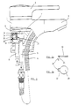
- the sanitary fitting shown in Figure 1 comprises in a known manner a fitting body 1, a rotatable and pivotable operating lever 2 and an extendable outlet mouthpiece 3.
- the latter is via a shower hose 4 placed in a loop, which is partly inside the fitting body 1 and partly through the Hole of the wash basin to be thought below the sanitary fitting is connected to an outlet pipe 5.
- the outlet pipe 5 is fastened in a base part 6, which rests on an inner step of the valve body 1.
- the bottom part 6 carries a control cartridge 7, which can be constructed in a known manner and in which the control elements required for controlling the water flow or the water flows are combined. These control elements are moved in a suitable manner by means of the handle 2.
- Extend two inlet pipes 8 for cold or hot water also through the hole in the washbasin from below into the fitting body 1. They penetrate the base part 6 and communicate in a known manner with the control cartridge 7.
- the mixed water delivered by the control cartridge 7 depending on the relative position of the control elements reaches a somewhat enlarged chamber 10 via a short inlet channel 9 and from there via a channel 11, which continues the inlet channel 9 coaxially, to the outlet pipe 5 and from there to the extendable outlet mouthpiece 3rd
- a pipe interrupter is inserted into the chamber 10 from the side and bears the overall reference number 12. It comprises a hollow cylindrical housing 13, which is sealed by means of O-ring seals against the side wall of the chamber 10 in the base part 6 and against the inner wall of the valve body 1. The interior of the hollow cylindrical housing 13, the ventilation path 14, communicates with the outside atmosphere via a bore 15.
- FIG. 2a in the side view and in FIG. 2B in the bottom view.
- It consists of elastic material, preferably rubber or a comparable plastic. It comprises a fastening section 18, which is molded onto a lateral nose 17 (see FIG. 2B) and is bent essentially at 90 °, and a closing section 19 which is circular in the bottom view.
- a groove 20 runs at the transition line between the fastening section 18 and the lateral nose 17. which at this point forms a kind of hinge between the two sections 18 and 19.
- the fastening section 18 of the closing flap 16 is clamped between the outer wall of the housing 13 and the inner wall of the chamber 10, while the closing section 19 of the closing flap 16 is about the hinge formed by the groove 20 between that shown in solid lines Position and the position shown in broken lines can pivot.
- Normal operation is understood to mean a state of the sanitary fitting in which no negative pressure occurs in the line system including the inlet pipes 8.
- the closing section 19 of the closing flap 16 rests under slight elastic pressure on the right-hand end face of the housing 13 in FIG. 1 and prevents both the entry of air from the outside atmosphere into the inner region of the chamber 10 and the outflow of water the inner area of the chamber 10 via the ventilation hole 15 in the fitting body 1.
- the latter is particularly important when the loop of the shower hose 4 is still filled with water, the mouthpiece 3 is pulled out and raised. Without the closing flap 16 resting against the housing 13, the water still contained in the loop of the shower hose 4 would flow out of the ventilation hole 15.
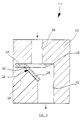
- FIG. 3 shows a second exemplary embodiment of a pipe interrupter, the structure of which largely corresponds to that described above. Corresponding components are therefore identified by the same reference symbols plus 100.
- the pipe interrupter 112 shown in FIG. 3 comprises a housing 113 which, with the addition of appropriate seals, can be inserted into a base part of a sanitary fitting in a similar manner as was the case with the exemplary embodiment from FIG. 1.
- the housing 113 of the pipe interrupter from FIG. 3 has an inlet channel 109, to which the mixed water emerging from the control cartridge is fed.
- the inlet channel 109 opens into an inner chamber 110 of the housing 113, into which a channel 111 also opens axially parallel and an aeration channel 114 at an obtuse angle to the inlet channel 109.
- a closing flap 116 which has a fastening section 118 and a closing section 119.
- the sections close in accordance with the different geometry of the channels 109, 114 in the housing 113 118 and 119 of the closing flap 116 make an obtuse angle with one another.
- a fillet 120 which supports the hinge effect of this area.
- the mode of operation of the pipe interrupter shown in FIG. 3 is completely the same as that of the exemplary embodiment in FIG. 1, except that the pivoting range of the closing section 119 in the exemplary embodiment in FIG. 3 is smaller than in the exemplary embodiment in FIG. 1.
- the closing section of the closing flap is made of hard material. It has elastic supports on both sides, which provide a seal against the mouth openings of the ventilation path and the inlet channel. As an alternative to these elastic supports, the mouth openings can also be surrounded by elastic seals.
Landscapes
- Life Sciences & Earth Sciences (AREA)
- Engineering & Computer Science (AREA)
- Hydrology & Water Resources (AREA)
- Public Health (AREA)
- Water Supply & Treatment (AREA)
- Health & Medical Sciences (AREA)
- Self-Closing Valves And Venting Or Aerating Valves (AREA)
- Bathtubs, Showers, And Their Attachments (AREA)
- Sink And Installation For Waste Water (AREA)
- Devices For Dispensing Beverages (AREA)
- Low-Molecular Organic Synthesis Reactions Using Catalysts (AREA)
- Steroid Compounds (AREA)
- Nitrogen Condensed Heterocyclic Rings (AREA)
- Domestic Plumbing Installations (AREA)
- Infusion, Injection, And Reservoir Apparatuses (AREA)
- Dowels (AREA)
- Valve Housings (AREA)
Priority Applications (1)
| Application Number | Priority Date | Filing Date | Title |
|---|---|---|---|
| AT89119491T ATE83818T1 (de) | 1988-10-31 | 1989-10-20 | Sanitaerarmatur mit rohrunterbrecher. |
Applications Claiming Priority (2)
| Application Number | Priority Date | Filing Date | Title |
|---|---|---|---|
| DE3837032A DE3837032A1 (de) | 1988-10-31 | 1988-10-31 | Rohrunterbrecher fuer sanitaere anlagen, insbesondere zum einbau in eine sanitaerarmatur |
| DE3837032 | 1988-10-31 |
Publications (2)
| Publication Number | Publication Date |
|---|---|
| EP0367043A1 EP0367043A1 (de) | 1990-05-09 |
| EP0367043B1 true EP0367043B1 (de) | 1992-12-23 |
Family
ID=6366241
Family Applications (1)
| Application Number | Title | Priority Date | Filing Date |
|---|---|---|---|
| EP89119491A Expired - Lifetime EP0367043B1 (de) | 1988-10-31 | 1989-10-20 | Sanitärarmatur mit Rohrunterbrecher |
Country Status (8)
| Country | Link |
|---|---|
| US (1) | US5009247A (enExample) |
| EP (1) | EP0367043B1 (enExample) |
| AT (1) | ATE83818T1 (enExample) |
| AU (1) | AU617886B2 (enExample) |
| CA (1) | CA2001734C (enExample) |
| DE (1) | DE3837032A1 (enExample) |
| ES (1) | ES2036780T3 (enExample) |
| FI (1) | FI87248C (enExample) |
Families Citing this family (19)
| Publication number | Priority date | Publication date | Assignee | Title |
|---|---|---|---|---|
| CH681164A5 (enExample) * | 1989-12-13 | 1993-01-29 | Karrer Weber & Cie Ag | |
| CH681731A5 (enExample) * | 1990-01-26 | 1993-05-14 | Kugler Fonderie Robinetterie | |
| AU632201B2 (en) * | 1990-02-05 | 1992-12-17 | Friedrich Grohe Ag | Water tap fitting with reverse-suction prevention |
| CH680517A5 (enExample) * | 1990-04-20 | 1992-09-15 | Wallisellen Ag Armaturen | |
| CH682682A5 (de) * | 1990-05-08 | 1993-10-29 | Karrer Weber & Cie Ag | Sanitäre Armatur. |
| US5329957A (en) * | 1991-08-28 | 1994-07-19 | Emhart Inc. | Fluid flow system vacuum breaker |
| US5349987A (en) * | 1994-01-24 | 1994-09-27 | Shieh Ming Dang | Faucet with a movable extension nozzle |
| US5361431A (en) * | 1994-02-02 | 1994-11-08 | Kohler Co. | Vacuum breaker for faucets |
| US5546978A (en) * | 1994-06-22 | 1996-08-20 | Plumbmaster, Inc. | Replacement faucet spayer hose installation kit |
| US5575424A (en) * | 1994-10-20 | 1996-11-19 | Kohler Co. | Vacuum breaker for faucets |
| DE19513569C1 (de) * | 1995-04-18 | 1996-11-21 | Ideal Standard | Sanitäres Wasserventil |
| US5701926A (en) * | 1995-06-07 | 1997-12-30 | The Rubinet Faucet Company | Backflow prevention device and vacuum breaker for kitchen plumbing |
| NL1002478C2 (nl) * | 1996-02-28 | 1997-08-29 | Peteri B V | Heetwaterkraan. |
| US5983923A (en) * | 1996-04-10 | 1999-11-16 | Lsp Products Group, Inc. | Water service box and connectors for PEX pipe |
| US5839464A (en) * | 1997-01-09 | 1998-11-24 | Emhart Inc. | Cartridge valve with vacuum breaker |
| US6125875A (en) * | 1999-03-08 | 2000-10-03 | Moen Incorporated | Pullout faucet value body with integral vacuum breaker hub |
| US6123106A (en) * | 1999-12-03 | 2000-09-26 | Emhart Inc. | Thrust washer |
| DE10125981C5 (de) * | 2001-05-29 | 2014-09-25 | Hansgrohe Se | Sanitärarmaturenblock |
| DE10230851B4 (de) * | 2002-07-04 | 2009-07-09 | Hansgrohe Ag | Sanitärarmatur |
Family Cites Families (19)
| Publication number | Priority date | Publication date | Assignee | Title |
|---|---|---|---|---|
| DE608721C (de) * | 1935-01-30 | Guenther Thiem Dr Ing | Rueckschlagklappenventil | |
| US2302150A (en) * | 1939-10-13 | 1942-11-17 | Sloan Valve Co | Vacuum breaker |
| US2302151A (en) * | 1941-07-30 | 1942-11-17 | Sloan Valve Co | Vacuum breaker |
| US2378613A (en) * | 1941-12-01 | 1945-06-19 | Arrowhead Rubber Company | Fuel tank flapper valve |
| US2449573A (en) * | 1943-08-31 | 1948-09-21 | White William Sears | Safety device for fluid supply lines |
| US2877789A (en) * | 1957-11-06 | 1959-03-17 | Sloan Valve Co | Vacuum breakers |
| SE205191C1 (sv) * | 1961-07-04 | 1966-06-07 | Aga Ab | Ventildon för andningsapparater |
| DE1205352B (de) * | 1962-03-29 | 1965-11-18 | Eugen Esswein | Auslaufventil fuer Schlauchanschluss mit Rohrbeluefter |
| US3207171A (en) * | 1962-05-09 | 1965-09-21 | R E Chapin Mfg Works Inc | Back-flow preventing valve |
| US3292658A (en) * | 1963-07-15 | 1966-12-20 | Scaramucci Domer | Check valve and resilient hinge structure and method for manufacturing same |
| US3295547A (en) * | 1964-02-10 | 1967-01-03 | Scaramucci Domer | Foldable check valve |
| DE2249366A1 (de) * | 1971-10-11 | 1973-04-19 | Hitachi Ltd | Verfahren und vorrichtung zur kontrolle und steuerung der breite eines gewalzten bandes |
| US3814124A (en) * | 1972-09-20 | 1974-06-04 | Exxon Research Engineering Co | Thermoplastic check valve |
| US4063570A (en) * | 1976-08-19 | 1977-12-20 | Mitchell H Charles | Backflow check valve |
| US4080981A (en) * | 1976-10-12 | 1978-03-28 | Stewart Anthony F | Antisiphon check valve |
| US4217921A (en) * | 1978-06-16 | 1980-08-19 | Zurn Industries, Inc. | Back flow preventer valve |
| US4508136A (en) * | 1982-09-29 | 1985-04-02 | Kah Jr Carl L C | Anti-syphon flow control valve |
| DE3603503A1 (de) * | 1986-02-05 | 1987-08-06 | Grohe Armaturen Friedrich | Mischbatterie mit schlauchbrausenauslauf |
| DE3706737A1 (de) * | 1987-03-02 | 1988-09-15 | Schubert & Salzer Maschinen | Rohrunterbrecher |
-
1988
- 1988-10-31 DE DE3837032A patent/DE3837032A1/de active Granted
-
1989
- 1989-10-20 EP EP89119491A patent/EP0367043B1/de not_active Expired - Lifetime
- 1989-10-20 ES ES198989119491T patent/ES2036780T3/es not_active Expired - Lifetime
- 1989-10-20 AT AT89119491T patent/ATE83818T1/de not_active IP Right Cessation
- 1989-10-24 US US07/425,944 patent/US5009247A/en not_active Expired - Fee Related
- 1989-10-25 AU AU43716/89A patent/AU617886B2/en not_active Ceased
- 1989-10-26 FI FI895093A patent/FI87248C/fi not_active IP Right Cessation
- 1989-10-30 CA CA002001734A patent/CA2001734C/en not_active Expired - Fee Related
Also Published As
| Publication number | Publication date |
|---|---|
| AU4371689A (en) | 1990-05-03 |
| DE3837032C2 (enExample) | 1992-05-14 |
| US5009247A (en) | 1991-04-23 |
| FI87248B (fi) | 1992-08-31 |
| EP0367043A1 (de) | 1990-05-09 |
| FI87248C (fi) | 1992-12-10 |
| FI895093A0 (fi) | 1989-10-26 |
| CA2001734C (en) | 1994-11-08 |
| DE3837032A1 (de) | 1990-05-03 |
| AU617886B2 (en) | 1991-12-05 |
| ATE83818T1 (de) | 1993-01-15 |
| ES2036780T3 (es) | 1993-06-01 |
| CA2001734A1 (en) | 1990-04-30 |
Similar Documents
| Publication | Publication Date | Title |
|---|---|---|
| EP0367043B1 (de) | Sanitärarmatur mit Rohrunterbrecher | |
| EP0432553B1 (de) | Sanitäre Armatur | |
| DE19508631C1 (de) | Durchflußbegrenzendes Ventil zum Einfügen zwischen einen Brauseschlauch und eine Handbrause | |
| EP0455998B1 (de) | Sanitäre Armatur | |
| DE60113520T2 (de) | Wasserhahn mit vakuumschutzschalter | |
| DE3811162A1 (de) | Mit unterdruck arbeitende abwasseranordnung | |
| DE19623104C2 (de) | Als Einhebelmischer ausgebildete Sanitärarmatur | |
| EP1789636B1 (de) | Sanitäre auslaufeinheit | |
| EP0370281B1 (de) | Rohrunterbrecher für sanitäre Anlagen, insbesondere zum Einbau in eine Sanitärarmatur | |
| DE3536947C1 (de) | Druckspueler mit integrierter Vorabsperrung | |
| DE69715751T2 (de) | An ein mehrstufiges Umschaltventil angeflanschter Druckregler | |
| EP0444414B1 (de) | Sanitäre Armatur mit einer Sicherungseinrichtung zum verhindern des Zurückfliessens von Wasser | |
| DE2407933B2 (de) | Umleitventil für Brausen-Wannen-Armaturen | |
| DE3326083A1 (de) | Ventil | |
| DD296726A5 (de) | Einloch-mischbatterie mit ausziehbarer handbrause | |
| EP4018047A1 (de) | Stagnationsspülventilvorrichtung | |
| WO2011076320A1 (de) | Sanitäre auslaufeinheit | |
| EP1941196B1 (de) | Sanitäres umstellventil | |
| DE3009599A1 (de) | Unterputz-anschlusskasten fuer sanitaerarmaturen | |
| DE3939224C2 (de) | Sanitäre Mischarmatur | |
| DE102021108028A1 (de) | Strahlregler für eine Sanitärarmatur, Sanitärarmatur und Verwendung eines Strahlreglers | |
| DE68922114T2 (de) | Mischventil mit kugelsteuerungsmechanik. | |
| EP2280783B1 (de) | Handbrause mit einem an einem handgriff angeordneten brausekopf | |
| DE2945834A1 (de) | Ventil fuer fluide, insbesondere in einem spueler, einer mischbatterie oder einem hahn o.dgl. armaturen fuer installationszwecke | |
| DE3934216A1 (de) | Einloch-mischbatterie mit ausziehbarer handbrause |
Legal Events
| Date | Code | Title | Description |
|---|---|---|---|
| PUAI | Public reference made under article 153(3) epc to a published international application that has entered the european phase |
Free format text: ORIGINAL CODE: 0009012 |
|
| AK | Designated contracting states |
Kind code of ref document: A1 Designated state(s): AT CH ES FR GB IT LI NL SE |
|
| 17P | Request for examination filed |
Effective date: 19900414 |
|
| 17Q | First examination report despatched |
Effective date: 19910703 |
|
| GRAA | (expected) grant |
Free format text: ORIGINAL CODE: 0009210 |
|
| AK | Designated contracting states |
Kind code of ref document: B1 Designated state(s): AT CH ES FR GB IT LI NL SE |
|
| REF | Corresponds to: |
Ref document number: 83818 Country of ref document: AT Date of ref document: 19930115 Kind code of ref document: T |
|
| ET | Fr: translation filed | ||
| GBT | Gb: translation of ep patent filed (gb section 77(6)(a)/1977) |
Effective date: 19920205 |
|
| ITF | It: translation for a ep patent filed | ||
| REG | Reference to a national code |
Ref country code: ES Ref legal event code: FG2A Ref document number: 2036780 Country of ref document: ES Kind code of ref document: T3 |
|
| PLBI | Opposition filed |
Free format text: ORIGINAL CODE: 0009260 |
|
| 26 | Opposition filed |
Opponent name: FA. IDEAL-STANDARD GMBH Effective date: 19930728 |
|
| NLR1 | Nl: opposition has been filed with the epo |
Opponent name: FA. IDEAL-STANDARD GMBH |
|
| PLBN | Opposition rejected |
Free format text: ORIGINAL CODE: 0009273 |
|
| STAA | Information on the status of an ep patent application or granted ep patent |
Free format text: STATUS: OPPOSITION REJECTED |
|
| 27O | Opposition rejected |
Effective date: 19940818 |
|
| EAL | Se: european patent in force in sweden |
Ref document number: 89119491.2 |
|
| NLR2 | Nl: decision of opposition | ||
| PGFP | Annual fee paid to national office [announced via postgrant information from national office to epo] |
Ref country code: GB Payment date: 19990922 Year of fee payment: 11 |
|
| PG25 | Lapsed in a contracting state [announced via postgrant information from national office to epo] |
Ref country code: GB Free format text: LAPSE BECAUSE OF NON-PAYMENT OF DUE FEES Effective date: 20001020 |
|
| PGFP | Annual fee paid to national office [announced via postgrant information from national office to epo] |
Ref country code: SE Payment date: 20001026 Year of fee payment: 12 |
|
| GBPC | Gb: european patent ceased through non-payment of renewal fee |
Effective date: 20001020 |
|
| PG25 | Lapsed in a contracting state [announced via postgrant information from national office to epo] |
Ref country code: SE Free format text: LAPSE BECAUSE OF NON-PAYMENT OF DUE FEES Effective date: 20011021 |
|
| EUG | Se: european patent has lapsed |
Ref document number: 89119491.2 |
|
| PGFP | Annual fee paid to national office [announced via postgrant information from national office to epo] |
Ref country code: NL Payment date: 20021031 Year of fee payment: 14 |
|
| PGFP | Annual fee paid to national office [announced via postgrant information from national office to epo] |
Ref country code: ES Payment date: 20031021 Year of fee payment: 15 |
|
| PGFP | Annual fee paid to national office [announced via postgrant information from national office to epo] |
Ref country code: FR Payment date: 20031023 Year of fee payment: 15 Ref country code: CH Payment date: 20031023 Year of fee payment: 15 |
|
| PGFP | Annual fee paid to national office [announced via postgrant information from national office to epo] |
Ref country code: AT Payment date: 20031126 Year of fee payment: 15 |
|
| PG25 | Lapsed in a contracting state [announced via postgrant information from national office to epo] |
Ref country code: NL Free format text: LAPSE BECAUSE OF NON-PAYMENT OF DUE FEES Effective date: 20040501 |
|
| NLV4 | Nl: lapsed or anulled due to non-payment of the annual fee |
Effective date: 20040501 |
|
| PG25 | Lapsed in a contracting state [announced via postgrant information from national office to epo] |
Ref country code: AT Free format text: LAPSE BECAUSE OF NON-PAYMENT OF DUE FEES Effective date: 20041020 |
|
| PG25 | Lapsed in a contracting state [announced via postgrant information from national office to epo] |
Ref country code: ES Free format text: LAPSE BECAUSE OF NON-PAYMENT OF DUE FEES Effective date: 20041021 |
|
| PG25 | Lapsed in a contracting state [announced via postgrant information from national office to epo] |
Ref country code: LI Free format text: LAPSE BECAUSE OF NON-PAYMENT OF DUE FEES Effective date: 20041031 Ref country code: CH Free format text: LAPSE BECAUSE OF NON-PAYMENT OF DUE FEES Effective date: 20041031 |
|
| REG | Reference to a national code |
Ref country code: CH Ref legal event code: PL |
|
| PG25 | Lapsed in a contracting state [announced via postgrant information from national office to epo] |
Ref country code: FR Free format text: LAPSE BECAUSE OF NON-PAYMENT OF DUE FEES Effective date: 20050630 |
|
| REG | Reference to a national code |
Ref country code: FR Ref legal event code: ST |
|
| PG25 | Lapsed in a contracting state [announced via postgrant information from national office to epo] |
Ref country code: IT Free format text: LAPSE BECAUSE OF NON-PAYMENT OF DUE FEES;WARNING: LAPSES OF ITALIAN PATENTS WITH EFFECTIVE DATE BEFORE 2007 MAY HAVE OCCURRED AT ANY TIME BEFORE 2007. THE CORRECT EFFECTIVE DATE MAY BE DIFFERENT FROM THE ONE RECORDED. Effective date: 20051020 |
|
| REG | Reference to a national code |
Ref country code: ES Ref legal event code: FD2A Effective date: 20041021 |