EP0365979B1 - Diagnostisches Röntgenstrahlgerät - Google Patents
Diagnostisches Röntgenstrahlgerät Download PDFInfo
- Publication number
- EP0365979B1 EP0365979B1 EP89119280A EP89119280A EP0365979B1 EP 0365979 B1 EP0365979 B1 EP 0365979B1 EP 89119280 A EP89119280 A EP 89119280A EP 89119280 A EP89119280 A EP 89119280A EP 0365979 B1 EP0365979 B1 EP 0365979B1
- Authority
- EP
- European Patent Office
- Prior art keywords
- data
- slice
- ray
- solid
- image pickup
- Prior art date
- Legal status (The legal status is an assumption and is not a legal conclusion. Google has not performed a legal analysis and makes no representation as to the accuracy of the status listed.)
- Expired - Lifetime
Links
Images


Classifications
-
- A—HUMAN NECESSITIES
- A61—MEDICAL OR VETERINARY SCIENCE; HYGIENE
- A61B—DIAGNOSIS; SURGERY; IDENTIFICATION
- A61B6/00—Apparatus for radiation diagnosis, e.g. combined with radiation therapy equipment
- A61B6/42—Apparatus for radiation diagnosis, e.g. combined with radiation therapy equipment with arrangements for detecting radiation specially adapted for radiation diagnosis
- A61B6/4208—Apparatus for radiation diagnosis, e.g. combined with radiation therapy equipment with arrangements for detecting radiation specially adapted for radiation diagnosis characterised by using a particular type of detector
- A61B6/4225—Apparatus for radiation diagnosis, e.g. combined with radiation therapy equipment with arrangements for detecting radiation specially adapted for radiation diagnosis characterised by using a particular type of detector using image intensifiers
-
- A—HUMAN NECESSITIES
- A61—MEDICAL OR VETERINARY SCIENCE; HYGIENE
- A61B—DIAGNOSIS; SURGERY; IDENTIFICATION
- A61B6/00—Apparatus for radiation diagnosis, e.g. combined with radiation therapy equipment
- A61B6/02—Devices for diagnosis sequentially in different planes; Stereoscopic radiation diagnosis
- A61B6/03—Computerised tomographs
- A61B6/032—Transmission computed tomography [CT]
Definitions
- the present invention relates to an X-ray apparatus according to the pre-characterising part of claim 1 and to a method of obtaining a tomogram according to the pre-characterizing part of claim 9.
- simulation for a treatment program is performed in order to determine an amount of X-ray emission, a direction of X-ray emission, and the like prior to X-ray diagnosis and X-ray treatment.
- a tomogram is often obtained in addition to a fluorogram.
- a conventional X-ray fluoroscopic apparatus can obtain only a fluorogram
- a tomogram must be obtained using another CT apparatus. This operation is complicated and time-consuming.
- the health of the patient may be adversely affected. Therefore, a demand has arisen for developing an X-ray diagnostic apparatus which can obtain a tomogram in addition to a fluorogram.
- Fig. 1 shows an arrangement of a diagnostic X-ray apparatus which is constructed by additionally providing a function for obtaining a tomogram on the basis of the conventional X-ray fluoroscopic apparatus.
- the X-ray apparatus in Fig. 1 has been developed in accordance with the above-mentioned demand.
- X-ray beam emitted from an X-ray tube 14 is emitted onto one slice of an object 10 to be examined on a bed 12 through a diaphragm 16 for defining the slice having a predetermined thickness.
- the diaphragm 16 has a rectangular aperture perpendicular to the axis of the object 10.
- the slice of the object 10 is exposed with fan X-ray emitted from the diaphragm 16.
- the X-ray transmitted through one slice of the object 10 is incident on an image intensifier 18.
- the transmitted X-ray representing the degree of X-ray absorbance of tissues in the slice is converted into a light beam, and is output.
- the light beam is incident on a TV camera 22 through an optical system 20, and is converted into an analog signal, thus obtaining a projection signal representing the degree of X-ray absorbance of tissues in the slice.
- the X-ray tube 14, the diaphragm 16, the image intensifier 18, the optical system 20, and the TV camera 22 are aligned along a line, and can be integrally rotated in a direction indicated by an arrow A in Fig. 1 with respect to the object 10 in order to obtain a tomogram.
- the above units can be arranged to face any direction with respect to the object 10.
- the analog projection signal output from the TV camera 22 is converted into a digital signal by an A/D converter 24, thus obtaining X-ray projection data.
- an X-ray is emitted for each predetermined angle, and X-ray projection data at each angle is written in a memory 26.
- the projection data read out from the memory 26 is supplied to an image reconstruction processor 28, and a tomogram of the slice is reconstructed.
- the obtained tomogram is input to a display 32 through a D/A converter 30, and is displayed.
- the X-ray apparatus with the above arrangement can acquire X-ray projection data in the same manner as in the conventional CT apparatus by emitting an X-ray onto one slice of the object through the diaphragm 16, and by using the image intensifier 18 and the TV camera 22 as X-ray detectors.
- the diaphragm 16 may be removed to emit X-ray onto a given area of the object, and an output from the TV camera 22 or the memory 26 may be displayed or recorded.
- Such an X-ray apparatus has the following problems.
- a screen of the image intensifier 18 has a circular shape and an imaging area of the TV camera 22 has a square shape in order to obtain a fluorogram.
- an X-ray is emitted onto a slice of the object 10 through the diaphragm 16. Therefore, as shown in Fig. 2, a light beam from the image intensifier 18 is only incident on a strip region 34 of an imaging area 33 of the TV camera 22.
- the strip region 34 corresponds to the slice.
- the TV camera 22 normally performs a scanning operation, i.e., the entire imaging area 33 (regions 36, 34, and 38) is scanned, the regions 36 and 38 which receive no light beams are unnecessarily scanned.
- This operation is a waste of time. Therefore, when a tomogram is obtained, a time period required for acquiring projection data is unnecessarily prolonged. As a result, a time for obtaining a tomogram is undesirably prolonged.
- unnecessary data read out from the regions 36 and 38 are written in the memory 26, the memory 26 cannot be effectively used.
- the present invention provides for an X-ray fluoroscopic apparatus comprising an image intensifier and a TV camera formed of a solid-state image pickup device, wherein in a tomography mode, only necessary data in a part of the imaging area, on which a light beam is incident from the image intensifier, is read out from the solid-state image pickup device at normal speed, the readout data is written in a memory to reconstruct a tomogram, a time period required for acquiring data is shortened, and the memory is effectively used.
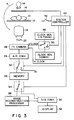
- FIG. 3 is a block diagram showing an arrangement of the embodiment.
- the same reference numerals in Fig. 3 denote the corresponding parts as in Fig. 1.
- a diaphragm 16 has a motor (not shown). Using the motor, the position and width of an aperture of the diaphragm can be changed. In a fluorography mode, the width of the aperture is increased to correspond the entire surface of a screen, to which an X-ray is incident, of an image intensifier 18. In a tomography mode, the size of the aperture is decreased so that its position and width correspond to a desired slice of an object 10 to be examined.
- a control signal is supplied from a system controller 44 to the diaphragm 16.
- a mode designation switch 42 is connected to the system controller 44 to select an operation mode, i.e., tomography or fluorography mode.
- an operation mode i.e., tomography or fluorography mode.
- the TV camera 22 is formed of solid-state image pickup device such as a CCD.
- An arrangement of the CCD is shown in Fig. 4.
- CCD of the other systems such as frame transfer system CCD may be employed.
- a large number of vertical transfer CCDs 62 are arranged on the imaging area of the TV camera 22.
- Each CCD 62 is divided into 512 lines (512 pixels), and data of the pixels are transferred line by line in the vertical direction indicated by an arrow B in synchronism with a vertical transfer clock.
- One horizontal transfer CCD 64 is arranged at the lower end of all the vertical transfer CCDs 62.
- the CCD 64 transfers pixel data of a line transferred from all the vertical transfer CCDs 62 pixel by pixel in the horizontal direction indicated by an arrow C in synchronism with a horizontal transfer clock.
- the data output from the CCD 64 is output through a buffer 66, and is supplied to an A/D converter 24.
- the TV camera 22 requires two types of vertical transfer clock signals. Therefore, a first clock generator 46 having a normal frequency (in this case, a frequency of a horizontal synchronizing signal of a TV signal of an NTSC system: 15.75 kHz), and a second clock generator 48 having a frequency (e.g., 10 MHz) higher than the normal frequency, are provided.
- the first and second clock signals from the generators 46 and 48 are supplied to the TV camera 22 through a selector 50.
- a selection operation of the selector 50 is controlled by the system controller 44.
- the selector 50 includes first and second terminals respectively connected to the first and second clock generators 46 and 48, and a third terminal which is grounded. The third terminal is used to interrupt a vertical transfer operation.
- the horizontal transfer clock signal is directly supplied from the system controller 44 to the TV camera 22, and its frequency is always kept constant.
- An output from the A/D converter 24 is supplied to a selector 52.
- the selector 52 includes a first terminal connected to a memory 26, and a second terminal which is grounded. A selection operation of the selector 52 is also controlled by the system controller 44.
- the selector 52 is switched to the first terminal side to write the readout data in the memory 26.
- the selector 52 is switched to the second terminal side to discharge the readout data through the ground terminal. Therefore, non-effective use of the memory 26, caused by storage of unnecessary data, can be prevented. Note that X-ray projection data from a large number of directions acquired upon one rotation of an X-ray tube 14 around the object 10 are stored in the memory 26.
- An output from the memory 26 is input to a selector 54.
- the selector 54 includes a first terminal connected to an image reconstruction processor 28, and a second terminal connected to a D/A converter 30.
- the selector 54 is switched by the system controller 44 to supply an output from the memory 26 to the image reconstruction processor 28 in a tomography mode, and to directly supply the output from the memory 26 to the D/A converter 30 in a fluorography mode. Note that, in the fluorography mode, an output from the TV camera 22 may be directly supplied to a display 32, and may be displayed thereby.
- the system controller 44 supplies a control signal to the diaphragm 16, and the width of the aperture of the diaphragm 16 is decreased to a predetermined width at a predetermined position corresponding to a slice of the object.
- the selector 54 is connected to the first terminal side, and the output from the memory 26 is input to the image reconstruction processor 28, thus reconstructing the tomogram.
- the X-ray tube 14, the diaphragm 16, the image intensifier 18, the optical system 20, and the TV camera 22 are integrally rotated around the object 10 in a direction indicated by an arrow A in Fig.
- the system controller 44 internally generates a frame synchronizing signal, and controls the selector 50 in synchronism with the frame synchronizing signal and in accordance with the position and width of the aperture of the diaphragm 16 to supply the first or second vertical transfer clock signal to the TV camera 22.
- the system controller 44 also supplies a horizontal transfer clock signal having a constant frequency to the TV camera 22 at a predetermined timing.
- the system controller 44 also connects the selector 52 to the memory 26 during a predetermined period, and writes the necessary data in the memory 26.
- a light beam is not incident on the entire imaging area of the TV camera 22, but the light beam from the image intensifier 18 is incident on only a strip portion, corresponding to a slice of the object, onto which an X-ray limited by the diaphragm 16 is emitted.
- a light beam is incident on a region R (region consisting of four horizontal scanning lines, i.e., the 251st to 254th lines) in Fig. 4 corresponding to the slice.
- a region U1 consisting of the first to 250th horizontal scanning lines, and a region U2 consisting of the 255th to 512th horizontal scanning lines receive no light beams.
- X-ray projection data to be read out from the TV camera 22 and to be written in the memory 26 exist only in the region R. Pixel data in the regions U1 and U2 need not be written in the memory 26. In this embodiment, therefore, until data to be read out are written in the horizontal transfer CCD 64, the pixel data are vertically transferred at high speed, accumulated in the horizontal transfer CCD 64, integrally read out from the CCD 64, and discharged through the ground terminal through the second terminal of the selector 52 without being written in the memory 26.
- the data in the horizontal transfer CCD 64 are horizontally transferred, the data are vertically transferred at normal speed, and the data read out from the TV camera 22 are supplied to the memory 26 through the first terminal of the selector 52. Since the vertical transfer is performed at normal speed, the data in the next line are written in the horizontal transfer CCD 64 after the data of each line are output from the horizontal transfer CCD 64.
- a write operation of the data in the region R to the memory 26 is completed, high-speed vertical transfer, accumulation of the data in the horizontal transfer CCD 64, a read operation of the accumulated data, and a discharge operation of the readout data to the ground terminal are restarted.
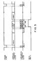
- This operation is shown in the timing chart in Fig. 5. More specifically, when the frame synchronizing signal is rendered active ("H" level), and an imaging period of one frame is started, the system controller 44 connects the selector 50 to the second terminal side, and the second clock signal having a frequency of 10 MHz is supplied to the TV camera 22 as a vertical transfer clock signal. At this time, the horizontal transfer clock is not supplied. Therefore, pixel data of each line is transferred at high speed in the vertical direction indicated by the downward arrow B in Fig. 4. The pixel data of the lines are sequentially transferred line by line from the lowermost 512th horizontal scanning line to the horizontal transfer CCD 64, and are stored or accumulated in the horizontal transfer CCD 64.
- a vertical transfer operation at this time can be performed at very high speed because a horizontal transfer operation for each line transfer is not required. Therefore, a transfer time period of data in the unnecessary region can be shortened.
- the system controller 44 supplies the horizontal transfer clock to the TV camera 22.
- the pixel data of the 512th to 255th lines accumulated in the horizontal transfer CCD 64 are horizontally transferred, and are output through the buffer 66.
- the selector 52 is still connected to the second terminal side, and the readout pixel data are discharged through the ground terminal, i.e., the data is not written in the memory 26.
- the selector 50 is switched to the first clock generator 46 side, and the vertical transfer clock signal having a frequency of 15.75 kHz is supplied to the TV camera 22.
- the pixel data is vertically transferred by one line, i.e., the pixel data of the lowermost 254th horizontal scanning line in the region R is transferred to the horizontal transfer CCD 64, the horizontal transfer clock signal is supplied, and the pixel data of the 254th line in the horizontal transfer CCD 64 are read out.
- the selector 52 is switched to the first terminal side, and these readout data are written in the memory 26.
- vertical and horizontal transfer operations of the pixel data of each line are repeated.
- the selector 50 is switched to the third terminal, and supply of the vertical transfer clock is interrupted.
- the selector 50 is connected to the second terminal, supply of the high-speed vertical transfer clock signal having a frequency of 10 MHz is restarted, and the selector 52 is switched to the ground terminal side. Note that supply of the horizontal transfer clock signal is interrupted at this time. Therefore, the pixel data of the 250th to first horizontal scanning lines in the unnecessary region U1 are transferred at high speed in the vertical direction indicated by the arrow B, and are accumulated in the horizontal transfer CCD 64.
- the selector 50 is connected to the third terminal side, and supply of the vertical transfer clock signal is interrupted.
- the horizontal transfer clock signal is transferred to the TV camera 22, and the pixel data of the 250th to first lines accumulated in the horizontal transfer CCD 64 are output.
- the selector 52 is connected to the ground terminal, and the readout pixel data are discharged through the ground terminal, i.e., are not written in the memory 26.
- the width of the aperture of the diaphragm 16 is increased, the selector 50 is always connected to the first clock generator 46 side, and the first clock signal having a frequency of 15.75 kHz is supplied as a vertical transfer clock signal.
- the horizontal transfer clock signal is always supplied, pixel data of the entire imaging area of the TV camera 22 is normally read out, the readout data is supplied to the display 32 through the A/D converter 24, the first terminal of the selector 52, the memory 26, the second terminal of the selector 54, and the D/A converter 30, and the data is displayed by the display 32.
- an X-ray fluoroscopic apparatus wherein an X-ray emitted onto the object is limited by the diaphragm to be incident onto only a desired slice of the object, data in only a region corresponding to the slice is read out from the TV camera 22 using the CCD for picking up an optical image output from the image intensifier 18 which converts the transmitted fluorogram into an optical image, the readout data is stored in the memory 26 to reconstruct the tomogram, and data except for the data corresponding to the slice are output at high speed and are discharged without storage in the memory 26. Therefore, a tomogram can be obtained in a short period of time required for acquiring X-ray projection data, and the memory 26 can be effectively used.
- Switch timings of the selectors 50 and 52 for controlling a read operation from the TV camera 22, and a write operation to the memory 26 are determined in accordance with the width and position of the aperture of the diaphragm 16 for defining the width and position of the slice. Therefore, the width and position of the slice can be changed. Therefore, the tomogram of the slice having an arbitrary width can be obtained at an arbitrary position of the object only when the arbitrary slice is located within the range of an X-ray incident screen of the image intensifier 18, and hence a degree of freedom of the tomography can be increased.
- this apparatus may obtain only a tomogram without a fluorogram.
- the solid-state image pickup device is not limited to a CCD, but a MOS device can be used.
Landscapes
- Health & Medical Sciences (AREA)
- Life Sciences & Earth Sciences (AREA)
- Engineering & Computer Science (AREA)
- Medical Informatics (AREA)
- Optics & Photonics (AREA)
- Biomedical Technology (AREA)
- Biophysics (AREA)
- High Energy & Nuclear Physics (AREA)
- Veterinary Medicine (AREA)
- Nuclear Medicine, Radiotherapy & Molecular Imaging (AREA)
- Public Health (AREA)
- Pathology (AREA)
- Radiology & Medical Imaging (AREA)
- Physics & Mathematics (AREA)
- Heart & Thoracic Surgery (AREA)
- Molecular Biology (AREA)
- Surgery (AREA)
- Animal Behavior & Ethology (AREA)
- General Health & Medical Sciences (AREA)
- Pulmonology (AREA)
- Theoretical Computer Science (AREA)
- Apparatus For Radiation Diagnosis (AREA)
- Studio Circuits (AREA)
Claims (10)
- Röntgengerät, umfassend:
eine Röntgenstrahlquelle (14), die Röntgenstrahlen aus einer großen Anzahl von Richtungen auf eine Scheibe eines Objekts (10) emittiert;
einen Bildverstärker (18) zum Umsetzen der durch die Scheibe hindurchgelangten Röntgenstrahlen in einen Lichtstrahl;
eine Festkörper-Bildaufnahmeeinrichtung (22) zum Erfassen des von dem Bildverstärker (18) ausgegebenen Lichtstrahls, um Röntgen-Projektionsdaten auszugeben;
eine Einrichtung (28) zum Erhalten eines Tomogramms der Scheibe entsprechend den von der Festkörper-Bildaufnahmeeinrichtung (22) ausgegebenen Röntgen-Projektionsdaten;
eine Speichereinrichtung (26) zum Speichern eines Ausgangssignals der Festkörper-Bildaufnahmeeinrichtung (22);
eine Einrichtung (42) zum Einstellen der Betriebsart auf eine erste oder eine zweite Betriebsart;
gekennzeichnet durch eine Leseeinrichtung (44) zum Auslesen von der Scheibe entsprechenden Bilddaten aus der Festkörper-Bildaufnahmeeinrichtung (22) mit einer ersten vorbestimmten Geschwindigkeit, um die ausgelesenen Bilddaten in der Speichereinrichtung (26) abzuspeichern, zum Auslesen von Bilddaten aus einer Zone mit Ausnahme der der Scheibe entsprechenden Zone aus der Festkörper-Bildaufnahmeeinrichtung mit einer zweiten Geschwindigkeit, die höher als die genannte erste vorbestimmte Geschwindigkeit ist, und zum Entfernen der ausgelesenen Daten ohne Speicherung in der Speichereinrichtung (26), im Rahmen der ersten Betriebsart, und zum Auslesen von Bilddaten des gesamten Abbildungsbereichs aus der Festkörper-Bildaufnahmeeinrichtung (22) mit der vorbestimmten Geschwindigkeit, um die ausgelesenen Daten in der Speichereinrichtung (26) abzuspeichern, im Rahmen der zweiten Betriebsart. - Vorrichtung nach Anspruch 1, gekennzeichnet durch:
eine Blendenanordnung (16) zum Begrenzen des von der Röntgenstrahlquelle (14) emittierten Röntgenstrahls, um den Röntgenstrahl auf eine Scheibe des Objekts in der ersten Betriebsart zu emittieren, und um in der zweiten Betriebsart den Röntgenstrahl zur Emittierung auf das Objekt, von dem ein Leuchtbild erhalten werden soll, nicht zu begrenzen;
eine Einrichtung zum gemeinsamen Drehen von Röntgenstrahlquelle, Blendenanordnung, Bildverstärker und Festkörper-Bildaufnahmeeinrichtung um das Objekt, um Röntgen-Projektionsdaten des Objekts aus einer großen Anzahl von Richtungen in der ersten Betriebsart zu erhalten;
eine Einrichtung (28) zum Rekonstruieren eines Tomogramms der Scheibe unter Verwendung der in der Speichereinrichtung enthaltenen Daten in der ersten Betriebsart;
eine erste Anzeigeeinrichtung zum Darstellen des rekonstruierten Tomogramms, und eine zweite Anzeigeeinrichtung zum Darstellen eines Leuchtbildes auf der Grundlage der Daten in dem Speicher, in der zweiten Betriebsart. - Vorrichtung nach Anspruch 2, dadurch gekennzeichnet, daß die Blendenanordnung eine Einrichtung zum Ändern des Maßes des in der ersten Betriebsart begrenzten Röntgenstrahls aufweist, um Lage und Dicke der Scheibe beliebig einzustellen.
- Vorrichtung nach Anspruch 3, dadurch gekennzeichnet, daß die Festkörper-Bildaufnahmeeinrichtung ein Zwischenzeilen-Transfersystem-CCD aufweist, welches aus einer großen Anzahl von Vertikal-Transfer-CCDs (62) und einem Horizontal-Transfer-CCD (64) gebildet ist; wobei die Blendenanordnung eine Einrichtung aufweist zum Begrenzen eines Röntgenstrahls in der vertikalen Richtung der Festkörper-Bildaufnahmeeinrichtung, um ein optisches Bild einzugeben, welches dem durch die Scheibe hindurchgegangenen Röntgenstrahl für nur eine oder eine Mehrzahl horizontaler Abtastzeilen im Bildbereich der Festkörper-Bildaufnahmeeinrichtung entspricht; und
wobei die Leseeinrichtung eine erste Einrichtung aufweist, um bei der über der vorbestimmten Geschwindigkeit liegenden höheren Geschwindigkeit Daten von Horizontalabtastzeilen mit Ausnahme der genannten einen oder der Mehrzahl von horizontalen Abtastzeilen, vertikal zu transferieren, die transferierten Daten in dem Horizontal-Transfer-CCD zu akkumulieren und die akkumulierten Daten aus dem Horizontal-Transfer-CCD in der ersten Betriebsart auszugeben, und eine zweite Einrichtung aufweist zum vertikalen Transferieren der Daten der einen oder der Mehrzahl von Horizontalabtastzeilen mit der vorbestimmten Geschwindigkeit, zum Ausgeben der Daten der einen horizontalen Abtastzeile aus dem Horizontal-Transfer-CCD, wenn die Daten der horizontalen Abtastzeile um eine Zeile vertikal transferiert sind, und zum Schreiben der Ausgabedaten in die Speichereinrichtung im Rahmen der ersten Betriebsart. - Vorrichtung nach Anspruch 4, dadurch gekennzeichnet, daß die Leseinrichtung eine Einrichtung (46) aufweist zum Erzeugen eines ersten Taktsignals mit einer ersten Frequenz entsprechend der vorbestimmten Geschwindigkeit, eine Einrichtung (48) zum Erzeugen eines zweiten Taktsignals mit einer zweiten Frequenz entsprechend der oberhalb der vorbestimmten Geschwindigkeit liegenden Geschwindigkeit, eine Einrichtung (50) zum Auswählen eines von dem ersten und dem zweiten Taktsignal nach Maßgabe der Lage der Scheibe, um das ausgewählte Taktsignal als ein Vertikal-Transfer-Taktsignal in der ersten Betriebsart an die Festkörper-Bildaufnahmeeinrichtung zu liefern, eine Einrichtung zum Zuführen eines Horizontal-Transfer-Taktsignals mit einer vorbestimmten Frequenz an die Festkörper-Aufnahmeeinrichtung synchron mit einem Auswahlvorgang der Auswahleinrichtung, und eine Einrichtung (52), die zwischen die Festkörper-Aufnahmeeinrichtung und die Speichereinrichtung geschaltet ist, um den Signalweg zwischen der Festkörper-Bildaufnahmeeinrichtung und der Speichereinrichtung synchron mit dem Auswahlvorgang der Auswahleinrichtung ein-/auszuschalten.
- Vorrichtung nach Anspruch 1, dadurch gekennzeichnet, daß
die Röntgenstrahlquelle eine Einrichtung zum Ändern der Lage und der Dicke der Scheibe, auf die der Röntgenstrahl zu emittieren ist, aufweist, und
die Festkörper-Bildaufnahmeeinrichtung ein CCD aufweist, um Bildelementdaten eines Vollbildes dadurch auszugeben, daß vertikaler und horizontaler Transfer der Bildelementdaten wiederholt werden; und
die Leseeinrichtung eine Einrichtung aufweist zum Transferieren lediglich von Bildelementdaten, die der Scheibe entsprechen, bei normaler Geschwindigkeit, und zum Transferieren von Bildelementdaten, die einer Zone außerhalb der Scheibe entsprechen, mit höherer Geschwindigkeit als der normalen Geschwindigkeit, und eine Gattereinrichtung aufweist, die an einen Ausgangsanschluß des CCD angeschlossen ist, um die bei normaler Geschwindigkeit transferierten Daten durchzulassen und den Durchgang von Daten, die mit höherer als der normalen Geschwindigkeit transferiert werden, zu unterbrechen. - Vorrichtung nach Anspruch 6, dadurch gekennzeichnet, daß die Festkörper-Bildaufnahmeeinrichtung ein Zwischenzeilen-Transfersystem-CCD aufweist, welches aus einer großen Anzahl von Vertikal-Transfer-CCDs (62) und einem Horizontal-Transfer-CCD (64) gebildet ist, von denen nur eine oder eine Mehrzahl vorbestimmter Horizontalabtastzeilen einen Lichtstrahl empfängt, der dem durch die Scheibe hindurch gegangenen Röntgenstrahl entspricht; und die Leseeinrichtung aufweist:
eine erste Einrichtung zum vertikalen Transferieren von Daten horizontaler Abtastzeilen mit Ausnahme der einen oder der Mehrzahl vorbestimmter horizontaler Abtastzeilen mit der über der Normalgeschwindigkeit liegenden Geschwindigkeit, zum Akkumulieren der übertragenen Daten in ein Horizontal-Transfer-CCD, und zum Ausgeben der akkumulierten Daten aus dem Horizontal-Transfer-CCD, und eine zweite Einrichtung zum vertikalen Transferieren der Daten der einen oder der Mehrzahl vorbestimmter Horizontalabtastzeilen bei normaler Geschwindigkeit. - Vorrichtung nach Anspruch 7 , dadurch gekennzeichnet, daß die Leseeinrichtung aufweist: Eine Einrichtung (46) zum Erzeugen eines ersten Taktsignals mit einer ersten Frequenz entsprechend der Normalgeschwindigkeit, eine Einrichtung (48) zum Erzeugen eines zweiten Taktsignals mit einer zweiten Frequenz entsprechend der oberhalb der Normalgeschwindigkeit liegenden höheren Geschwindigkeit, eine Einrichtung (50) zum Auswählen des ersten oder des zweiten Taktsignals nach Maßgabe der Lage und der Dicke der Scheibe, um das ausgewählte Signal der Festkörper-Bildaufnahmeeinrichtung als Vertikal-Transfer-Taktsignal zuzuführen, und einer Einrichtung zum Zuführen eines Horizontal-Transfer-Taktsignals mit einer vorbestimmten Frequenz zu der Festkörper-Bildaufnahineeinrichtung, synchron mit dem Auswahlvorgang der Auswahleinrichtung.
- Verfahren zum Erhalten eines Tomogramms unter Verwendung einer Röntgenstrahl-Leuchtbildapparatur, umfassend die Schrittea) Einfügen einer Blende (16) zwischen einer Röntgenstrahlquelle (14) und einem Objekt (10);b) Aussenden von Röntgenstrahlen aus einer großen Anzahl von Richtungen auf eine Scheibe des Objekts (10) durch die Blende, um den durch die Scheibe hindurchgehenden Röntgenstrahl auf einen Bildverstärker (18) auftreffen zu lassen;c) Lesen von Röntgen-Projektionsdaten aus einer Festkörper-Bildaufnahmeeinrichtung (22), die ein optisches, von dem Bildverstärker ausgegebenes Bild aufnimmt;d) Speichern der ausgelesenen Röntgen-Projektionsdaten in einem Speicher (26);e) Rekonstruieren eines Tomogramms nach Maßgabe der in dem Speicher (26) gespeicherten Röntgen-Projektionsdaten, gekennzeichnet durchLesen von der Scheibe entsprechenden Bilddaten aus der Aufnahmeeinrichtung (22) mit einer ersten vorbestimmten Geschwindigkeit und Speichern der ausgelesenen Bilddaten in dem Speicher (26); und
Lesen von einer Zone, die sich von der Zone der Scheibe unterscheidet, entsprechenden Bilddaten mit einer zweiten vorbestimmten Geschwindigkeit, die größer ist als die erste vorbestimmte Geschwindigkeit, und Ablegen der Bilddaten ohne Speicherung in dem Speicher (26). - Verfahren nach Anspruch 9, dadurch gekennzeichnet, daß
als die Festkörper-Bildaufnahmeeinrichtung ein Zwischenzeilen-Tranfersystem-CCD bereitgestellt wird, welches aus einer großen Anzahl von Vertikal-Transfer-CCDs (62) und einem Horizontal-Transfer-CCD (64) gebildet wird, wobei die Scheibe so gewählt wird, daß sie einer oder einer Mehrzahl von Horizontalabtastzeilen entspricht; und
der Schritt des Lesens von Röntgen-Projektionsdaten die Unterschritte aufweist:
kontinuierliches und vertikales Transferieren der Bildelementdaten unmittelbar bevor Daten der ersten Horizontalabtastzeile in einer der Scheibe entsprechenden Zone in einem Vollbild in das Horizontal-Transfer-CCD eingeschrieben werden;
Wiederholen des Vorgangs zum vertikalen Transferieren der Bildelementdaten um eine Zeile, nachdem die Daten in dem Horizontal-Transfer-CCD horizontal transferiert worden sind, bis Daten der letzten Horizontalabtastzeile in der Zone entsprechend der Scheibe von dem Horizontal-Transfer-CCD ausgeben sind; und
kontinuierliches und vertikales Transferieren der verbleibenden Bildelementdaten in dem einen Vollbild.
Applications Claiming Priority (2)
| Application Number | Priority Date | Filing Date | Title |
|---|---|---|---|
| JP63267497A JPH02114946A (ja) | 1988-10-24 | 1988-10-24 | X線診断装置 |
| JP267497/88 | 1988-10-24 |
Publications (2)
| Publication Number | Publication Date |
|---|---|
| EP0365979A1 EP0365979A1 (de) | 1990-05-02 |
| EP0365979B1 true EP0365979B1 (de) | 1995-06-07 |
Family
ID=17445673
Family Applications (1)
| Application Number | Title | Priority Date | Filing Date |
|---|---|---|---|
| EP89119280A Expired - Lifetime EP0365979B1 (de) | 1988-10-24 | 1989-10-17 | Diagnostisches Röntgenstrahlgerät |
Country Status (4)
| Country | Link |
|---|---|
| US (1) | US5027380A (de) |
| EP (1) | EP0365979B1 (de) |
| JP (1) | JPH02114946A (de) |
| DE (1) | DE68922956T2 (de) |
Families Citing this family (14)
| Publication number | Priority date | Publication date | Assignee | Title |
|---|---|---|---|---|
| US5247555A (en) * | 1988-10-28 | 1993-09-21 | Nucletron Manufacturing Corp. | Radiation image generating system and method |
| FR2668829B1 (fr) * | 1990-11-05 | 1993-10-22 | Commissariat Energie Atomique | Dispositif et procede de controle non destructif a acquisition simultanee de donnees radiographiques et de donnees tomographiques. |
| US5216250A (en) * | 1991-11-27 | 1993-06-01 | Lorad Corporation | Digital imaging system using CCD array |
| JP3056862B2 (ja) * | 1991-12-27 | 2000-06-26 | 日産自動車株式会社 | 新規な吸音材 |
| US5637846A (en) * | 1993-05-14 | 1997-06-10 | Ahold Retail Services Ag | Method and apparatus for electronic payment by a client in a self-service store |
| US5530935A (en) * | 1993-09-20 | 1996-06-25 | U.S. Philips Corporation | X-ray examination apparatus |
| US6091796A (en) * | 1994-11-23 | 2000-07-18 | Thermotrex Corporation | Scintillator based microscope |
| US6895077B2 (en) * | 2001-11-21 | 2005-05-17 | University Of Massachusetts Medical Center | System and method for x-ray fluoroscopic imaging |
| JP2004180715A (ja) * | 2002-11-29 | 2004-07-02 | Toshiba Corp | X線コンピュータ断層撮影装置 |
| US7123687B2 (en) | 2003-04-10 | 2006-10-17 | Varian Medical Systems Technologies, Inc. | Method for displaying digital X-ray image data at high resolution |
| JP4303540B2 (ja) * | 2003-09-01 | 2009-07-29 | Hoya株式会社 | デジタルカメラのノイズ抑制装置 |
| US7154994B2 (en) * | 2004-04-14 | 2006-12-26 | Varian Medical Systems, Inc. | Synchronization of x-ray data acquisition |
| US8923475B2 (en) * | 2012-01-31 | 2014-12-30 | Siemens Aktiengesellschaft | System and method for recording cone-beam tomograms in radiation therapy |
| DE102016117051A1 (de) | 2016-09-12 | 2018-03-15 | DüRR DENTAL AG | System und Verfahren zur Bereitstellung von Aufnahmeparametern |
Family Cites Families (7)
| Publication number | Priority date | Publication date | Assignee | Title |
|---|---|---|---|---|
| DE3010378C2 (de) * | 1980-03-18 | 1983-04-07 | Siemens AG, 1000 Berlin und 8000 München | Röntgendiagnostikeinrichtung für Aufnahme und Durchleuchtung |
| EP0105618B1 (de) * | 1982-09-07 | 1989-10-25 | The Board Of Trustees Of The Leland Stanford Junior University | Verfahren und Vorrichtung zur röntgenologischen Bilderzeugung mit Kompensation der Streustrahlung |
| JPS59155238A (ja) * | 1983-02-24 | 1984-09-04 | 株式会社東芝 | X線ct装置 |
| JPS60210087A (ja) * | 1984-04-03 | 1985-10-22 | Toshiba Corp | X線診断装置 |
| JPS61244184A (ja) * | 1985-04-23 | 1986-10-30 | Hitachi Ltd | ディジタルデータ変換システム |
| JPS6411533A (en) * | 1987-07-03 | 1989-01-17 | Toshiba Corp | X-ray diagnostic apparatus |
| US4884291A (en) * | 1988-07-11 | 1989-11-28 | Picker International, Inc. | X-ray television imaging using digital circular blanking |
-
1988
- 1988-10-24 JP JP63267497A patent/JPH02114946A/ja active Pending
-
1989
- 1989-10-17 EP EP89119280A patent/EP0365979B1/de not_active Expired - Lifetime
- 1989-10-17 US US07/422,661 patent/US5027380A/en not_active Expired - Fee Related
- 1989-10-17 DE DE68922956T patent/DE68922956T2/de not_active Expired - Fee Related
Also Published As
| Publication number | Publication date |
|---|---|
| US5027380A (en) | 1991-06-25 |
| DE68922956D1 (de) | 1995-07-13 |
| DE68922956T2 (de) | 1996-03-21 |
| JPH02114946A (ja) | 1990-04-27 |
| EP0365979A1 (de) | 1990-05-02 |
Similar Documents
| Publication | Publication Date | Title |
|---|---|---|
| EP0844588B1 (de) | Bildverarbeitungsgerät und -verfahren | |
| EP0365979B1 (de) | Diagnostisches Röntgenstrahlgerät | |
| US6437338B1 (en) | Method and apparatus for scanning a detector array in an x-ray imaging system | |
| JP5208877B2 (ja) | 実時間デジタルx線撮像装置 | |
| US5566218A (en) | Computerized tomography apparatus | |
| US5038369A (en) | X-ray fluoroscopic apparatus | |
| US20100189330A1 (en) | Radiographic tomography image generating apparatus | |
| EP1426009A1 (de) | Gerät und Verfahren zur Röntgentomographiebildgebung mit zerstörungsfrei auslesbarer Festkörperbildaufnahmevorrichtung | |
| RU2127961C1 (ru) | Телевизионная система высокого разрешения | |
| JP3435192B2 (ja) | X線診断装置 | |
| US20070036419A1 (en) | System and method for interactive definition of image field of view in digital radiography | |
| JPH067336A (ja) | X線画像を発生する方法及びx線装置 | |
| US7146032B2 (en) | Device and method for reading out an electronic image sensor that is subdivided into image points | |
| US20030197800A1 (en) | Method and apparatus for increasing the data acquisition rate in a digital detector | |
| US4555728A (en) | Digital fluorography | |
| US6285738B1 (en) | High-definition still picture real-time display type x-ray diagnostic apparatus | |
| EP1525849B1 (de) | Fluoroskopiegerät und -Verfahren | |
| JPH08510405A (ja) | X線装置 | |
| JP3160285B2 (ja) | X線診断装置 | |
| JP3088006B2 (ja) | 放射線診断装置における固体撮像デバイスの画像データ読み出し方法 | |
| JPH0884295A (ja) | X線撮像装置 | |
| JPH0715665A (ja) | X線tv装置 | |
| JPS59221093A (ja) | X線画像入力装置 | |
| JPH02207495A (ja) | X線透視撮影装置 |
Legal Events
| Date | Code | Title | Description |
|---|---|---|---|
| PUAI | Public reference made under article 153(3) epc to a published international application that has entered the european phase |
Free format text: ORIGINAL CODE: 0009012 |
|
| 17P | Request for examination filed |
Effective date: 19891017 |
|
| AK | Designated contracting states |
Kind code of ref document: A1 Designated state(s): DE NL |
|
| 17Q | First examination report despatched |
Effective date: 19930430 |
|
| GRAA | (expected) grant |
Free format text: ORIGINAL CODE: 0009210 |
|
| AK | Designated contracting states |
Kind code of ref document: B1 Designated state(s): DE NL |
|
| REF | Corresponds to: |
Ref document number: 68922956 Country of ref document: DE Date of ref document: 19950713 |
|
| PLBE | No opposition filed within time limit |
Free format text: ORIGINAL CODE: 0009261 |
|
| STAA | Information on the status of an ep patent application or granted ep patent |
Free format text: STATUS: NO OPPOSITION FILED WITHIN TIME LIMIT |
|
| 26N | No opposition filed | ||
| PGFP | Annual fee paid to national office [announced via postgrant information from national office to epo] |
Ref country code: DE Payment date: 20011029 Year of fee payment: 13 |
|
| PGFP | Annual fee paid to national office [announced via postgrant information from national office to epo] |
Ref country code: NL Payment date: 20011031 Year of fee payment: 13 |
|
| PG25 | Lapsed in a contracting state [announced via postgrant information from national office to epo] |
Ref country code: NL Free format text: LAPSE BECAUSE OF NON-PAYMENT OF DUE FEES Effective date: 20030501 Ref country code: DE Free format text: LAPSE BECAUSE OF NON-PAYMENT OF DUE FEES Effective date: 20030501 |
|
| NLV4 | Nl: lapsed or anulled due to non-payment of the annual fee |
Effective date: 20030501 |