EP0365979B1 - Diagnostic X-ray apparatus - Google Patents
Diagnostic X-ray apparatus Download PDFInfo
- Publication number
- EP0365979B1 EP0365979B1 EP89119280A EP89119280A EP0365979B1 EP 0365979 B1 EP0365979 B1 EP 0365979B1 EP 89119280 A EP89119280 A EP 89119280A EP 89119280 A EP89119280 A EP 89119280A EP 0365979 B1 EP0365979 B1 EP 0365979B1
- Authority
- EP
- European Patent Office
- Prior art keywords
- data
- slice
- ray
- solid
- image pickup
- Prior art date
- Legal status (The legal status is an assumption and is not a legal conclusion. Google has not performed a legal analysis and makes no representation as to the accuracy of the status listed.)
- Expired - Lifetime
Links
Images


Classifications
-
- A—HUMAN NECESSITIES
- A61—MEDICAL OR VETERINARY SCIENCE; HYGIENE
- A61B—DIAGNOSIS; SURGERY; IDENTIFICATION
- A61B6/00—Apparatus for radiation diagnosis, e.g. combined with radiation therapy equipment
- A61B6/42—Apparatus for radiation diagnosis, e.g. combined with radiation therapy equipment with arrangements for detecting radiation specially adapted for radiation diagnosis
- A61B6/4208—Apparatus for radiation diagnosis, e.g. combined with radiation therapy equipment with arrangements for detecting radiation specially adapted for radiation diagnosis characterised by using a particular type of detector
- A61B6/4225—Apparatus for radiation diagnosis, e.g. combined with radiation therapy equipment with arrangements for detecting radiation specially adapted for radiation diagnosis characterised by using a particular type of detector using image intensifiers
-
- A—HUMAN NECESSITIES
- A61—MEDICAL OR VETERINARY SCIENCE; HYGIENE
- A61B—DIAGNOSIS; SURGERY; IDENTIFICATION
- A61B6/00—Apparatus for radiation diagnosis, e.g. combined with radiation therapy equipment
- A61B6/02—Devices for diagnosis sequentially in different planes; Stereoscopic radiation diagnosis
- A61B6/03—Computerised tomographs
- A61B6/032—Transmission computed tomography [CT]
Description
- The present invention relates to an X-ray apparatus according to the pre-characterising part of
claim 1 and to a method of obtaining a tomogram according to the pre-characterizing part of claim 9. - Conventionally, simulation for a treatment program is performed in order to determine an amount of X-ray emission, a direction of X-ray emission, and the like prior to X-ray diagnosis and X-ray treatment. For the purpose of this simulation, a tomogram is often obtained in addition to a fluorogram. However, since a conventional X-ray fluoroscopic apparatus can obtain only a fluorogram, a tomogram must be obtained using another CT apparatus. This operation is complicated and time-consuming. In addition, when a patient is exposed with X-rays twice, the health of the patient may be adversely affected. Therefore, a demand has arisen for developing an X-ray diagnostic apparatus which can obtain a tomogram in addition to a fluorogram.
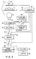
- Fig. 1 shows an arrangement of a diagnostic X-ray apparatus which is constructed by additionally providing a function for obtaining a tomogram on the basis of the conventional X-ray fluoroscopic apparatus. The X-ray apparatus in Fig. 1 has been developed in accordance with the above-mentioned demand. X-ray beam emitted from an X-ray tube 14 is emitted onto one slice of an
object 10 to be examined on abed 12 through adiaphragm 16 for defining the slice having a predetermined thickness. Thediaphragm 16 has a rectangular aperture perpendicular to the axis of theobject 10. The slice of theobject 10 is exposed with fan X-ray emitted from thediaphragm 16. When a fluorogram is obtained, thediaphragm 16 is removed. A case wherein a tomogram is obtained will be described hereinafter. The X-ray transmitted through one slice of theobject 10 is incident on animage intensifier 18. The transmitted X-ray representing the degree of X-ray absorbance of tissues in the slice is converted into a light beam, and is output. The light beam is incident on aTV camera 22 through anoptical system 20, and is converted into an analog signal, thus obtaining a projection signal representing the degree of X-ray absorbance of tissues in the slice. The X-ray tube 14, thediaphragm 16, theimage intensifier 18, theoptical system 20, and theTV camera 22 are aligned along a line, and can be integrally rotated in a direction indicated by an arrow A in Fig. 1 with respect to theobject 10 in order to obtain a tomogram. In addition, in order to obtain a fluorogram from an arbitrary direction, the above units can be arranged to face any direction with respect to theobject 10. - The analog projection signal output from the
TV camera 22 is converted into a digital signal by an A/D converter 24, thus obtaining X-ray projection data. While the X-ray tube 14 and the like are rotated once in the direction indicated by the arrow A in Fig. 1 around theobject 10, an X-ray is emitted for each predetermined angle, and X-ray projection data at each angle is written in amemory 26. The projection data read out from thememory 26 is supplied to animage reconstruction processor 28, and a tomogram of the slice is reconstructed. The obtained tomogram is input to adisplay 32 through a D/A converter 30, and is displayed. - The X-ray apparatus with the above arrangement can acquire X-ray projection data in the same manner as in the conventional CT apparatus by emitting an X-ray onto one slice of the object through the
diaphragm 16, and by using theimage intensifier 18 and theTV camera 22 as X-ray detectors. When a fluorogram is obtained, thediaphragm 16 may be removed to emit X-ray onto a given area of the object, and an output from theTV camera 22 or thememory 26 may be displayed or recorded. - Such an X-ray apparatus, however, has the following problems. A screen of the
image intensifier 18 has a circular shape and an imaging area of theTV camera 22 has a square shape in order to obtain a fluorogram. When a tomogram is obtained, however, an X-ray is emitted onto a slice of theobject 10 through thediaphragm 16. Therefore, as shown in Fig. 2, a light beam from theimage intensifier 18 is only incident on astrip region 34 of animaging area 33 of theTV camera 22. Thestrip region 34 corresponds to the slice. For this reason, when theTV camera 22 normally performs a scanning operation, i.e., the entire imaging area 33 (regions regions regions memory 26, thememory 26 cannot be effectively used. - It is the object of the present invention to provide an X-ray apparatus and a method of obtaining a tomogram which can acquire projection data for obtaining a tomogram in a short period of time.
- This is achieved by the present invention in accordance with the features of
claims 1 and 9, respectively. - The present invention provides for an X-ray fluoroscopic apparatus comprising an image intensifier and a TV camera formed of a solid-state image pickup device, wherein in a tomography mode, only necessary data in a part of the imaging area, on which a light beam is incident from the image intensifier, is read out from the solid-state image pickup device at normal speed, the readout data is written in a memory to reconstruct a tomogram, a time period required for acquiring data is shortened, and the memory is effectively used.
- According to such an X-ray apparatus, only projection data in a region of the imaging area, which receives a light beam from the image intensifier and corresponds to the slice, is effectively read out at normal speed, so that a time period required for acquiring data can be greatly shortened, and the memory for storing the acquired data can be effectively used.
- This invention can be more fully understood from the following detailed description when taken in conjunction with the accompanying drawings, in which:
- Fig. 1 is a schematic block diagram showing an arrangement of a conventional diagnostic X-ray apparatus;
- Fig. 2 is a view showing an imaging area of a TV camera in the apparatus shown in Fig. 1;
- Fig. 3 is a block diagram of a diagnostic X-ray apparatus according to an embodiment of the present invention;
- Fig. 4 is a view showing a two-dimensional structure of CCD used in a TV camera in the embodiment; and
- Fig. 5 is a timing chart showing an operation of the CCD.
- A diagnostic X-ray apparatus according to an embodiment of the present invention will be described hereinafter with reference to the accompanying drawings. Fig. 3 is a block diagram showing an arrangement of the embodiment. The same reference numerals in Fig. 3 denote the corresponding parts as in Fig. 1. A
diaphragm 16 has a motor (not shown). Using the motor, the position and width of an aperture of the diaphragm can be changed. In a fluorography mode, the width of the aperture is increased to correspond the entire surface of a screen, to which an X-ray is incident, of animage intensifier 18. In a tomography mode, the size of the aperture is decreased so that its position and width correspond to a desired slice of anobject 10 to be examined. For the purpose of this control operation, a control signal is supplied from asystem controller 44 to thediaphragm 16. Amode designation switch 42 is connected to thesystem controller 44 to select an operation mode, i.e., tomography or fluorography mode. The structure in which the X-ray transmitted through anobject 10 is incident on aTV camera 22 through animage intensifier 18 and anoptical system 20 is the same as in the apparatus shown in Fig. 1. - The
TV camera 22 is formed of solid-state image pickup device such as a CCD. An arrangement of the CCD is shown in Fig. 4. Although an interline transfer system CCD is employed as the solid-state image pickup device in Fig. 4, CCD of the other systems such as frame transfer system CCD may be employed. A large number ofvertical transfer CCDs 62 are arranged on the imaging area of theTV camera 22. EachCCD 62 is divided into 512 lines (512 pixels), and data of the pixels are transferred line by line in the vertical direction indicated by an arrow B in synchronism with a vertical transfer clock. Onehorizontal transfer CCD 64 is arranged at the lower end of all thevertical transfer CCDs 62. TheCCD 64 transfers pixel data of a line transferred from all thevertical transfer CCDs 62 pixel by pixel in the horizontal direction indicated by an arrow C in synchronism with a horizontal transfer clock. The data output from theCCD 64 is output through abuffer 66, and is supplied to an A/D converter 24. - In this embodiment, the
TV camera 22 requires two types of vertical transfer clock signals. Therefore, afirst clock generator 46 having a normal frequency (in this case, a frequency of a horizontal synchronizing signal of a TV signal of an NTSC system: 15.75 kHz), and a second clock generator 48 having a frequency (e.g., 10 MHz) higher than the normal frequency, are provided. The first and second clock signals from thegenerators 46 and 48 are supplied to theTV camera 22 through a selector 50. A selection operation of the selector 50 is controlled by thesystem controller 44. The selector 50 includes first and second terminals respectively connected to the first andsecond clock generators 46 and 48, and a third terminal which is grounded. The third terminal is used to interrupt a vertical transfer operation. The horizontal transfer clock signal is directly supplied from thesystem controller 44 to theTV camera 22, and its frequency is always kept constant. - An output from the A/
D converter 24 is supplied to aselector 52. Theselector 52 includes a first terminal connected to amemory 26, and a second terminal which is grounded. A selection operation of theselector 52 is also controlled by thesystem controller 44. When pixel data which have been vertically transferred in response to the first vertical transfer clock signal are output from the A/D converter 24, theselector 52 is switched to the first terminal side to write the readout data in thememory 26. When pixel data which have been vertically transferred in response to the second vertical transfer clock signal are read out from the A/D converter 24, theselector 52 is switched to the second terminal side to discharge the readout data through the ground terminal. Therefore, non-effective use of thememory 26, caused by storage of unnecessary data, can be prevented. Note that X-ray projection data from a large number of directions acquired upon one rotation of an X-ray tube 14 around theobject 10 are stored in thememory 26. - An output from the
memory 26 is input to aselector 54. Theselector 54 includes a first terminal connected to animage reconstruction processor 28, and a second terminal connected to a D/A converter 30. Theselector 54 is switched by thesystem controller 44 to supply an output from thememory 26 to theimage reconstruction processor 28 in a tomography mode, and to directly supply the output from thememory 26 to the D/A converter 30 in a fluorography mode. Note that, in the fluorography mode, an output from theTV camera 22 may be directly supplied to adisplay 32, and may be displayed thereby. - An operation of this embodiment will be described hereinafter. First, an operation in the tomography mode will be described below. In this mode, the
system controller 44 supplies a control signal to thediaphragm 16, and the width of the aperture of thediaphragm 16 is decreased to a predetermined width at a predetermined position corresponding to a slice of the object. In addition, theselector 54 is connected to the first terminal side, and the output from thememory 26 is input to theimage reconstruction processor 28, thus reconstructing the tomogram. The X-ray tube 14, thediaphragm 16, theimage intensifier 18, theoptical system 20, and theTV camera 22 are integrally rotated around theobject 10 in a direction indicated by an arrow A in Fig. 3 by each predetermined angle, and projection data is acquired at each angle as follows. Thesystem controller 44 internally generates a frame synchronizing signal, and controls the selector 50 in synchronism with the frame synchronizing signal and in accordance with the position and width of the aperture of thediaphragm 16 to supply the first or second vertical transfer clock signal to theTV camera 22. Thesystem controller 44 also supplies a horizontal transfer clock signal having a constant frequency to theTV camera 22 at a predetermined timing. Thesystem controller 44 also connects theselector 52 to thememory 26 during a predetermined period, and writes the necessary data in thememory 26. - As described above, in the tomography mode, a light beam is not incident on the entire imaging area of the
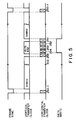
TV camera 22, but the light beam from theimage intensifier 18 is incident on only a strip portion, corresponding to a slice of the object, onto which an X-ray limited by thediaphragm 16 is emitted. In this case, assume that a light beam is incident on a region R (region consisting of four horizontal scanning lines, i.e., the 251st to 254th lines) in Fig. 4 corresponding to the slice. A region U1 consisting of the first to 250th horizontal scanning lines, and a region U2 consisting of the 255th to 512th horizontal scanning lines receive no light beams. X-ray projection data to be read out from theTV camera 22 and to be written in thememory 26 exist only in the region R. Pixel data in the regions U1 and U2 need not be written in thememory 26. In this embodiment, therefore, until data to be read out are written in thehorizontal transfer CCD 64, the pixel data are vertically transferred at high speed, accumulated in thehorizontal transfer CCD 64, integrally read out from theCCD 64, and discharged through the ground terminal through the second terminal of theselector 52 without being written in thememory 26. After the data to be read out are written in thehorizontal transfer CCD 64, the data in thehorizontal transfer CCD 64 are horizontally transferred, the data are vertically transferred at normal speed, and the data read out from theTV camera 22 are supplied to thememory 26 through the first terminal of theselector 52. Since the vertical transfer is performed at normal speed, the data in the next line are written in thehorizontal transfer CCD 64 after the data of each line are output from thehorizontal transfer CCD 64. When a write operation of the data in the region R to thememory 26 is completed, high-speed vertical transfer, accumulation of the data in thehorizontal transfer CCD 64, a read operation of the accumulated data, and a discharge operation of the readout data to the ground terminal are restarted. - This operation is shown in the timing chart in Fig. 5. More specifically, when the frame synchronizing signal is rendered active ("H" level), and an imaging period of one frame is started, the
system controller 44 connects the selector 50 to the second terminal side, and the second clock signal having a frequency of 10 MHz is supplied to theTV camera 22 as a vertical transfer clock signal. At this time, the horizontal transfer clock is not supplied. Therefore, pixel data of each line is transferred at high speed in the vertical direction indicated by the downward arrow B in Fig. 4. The pixel data of the lines are sequentially transferred line by line from the lowermost 512th horizontal scanning line to thehorizontal transfer CCD 64, and are stored or accumulated in thehorizontal transfer CCD 64. Unlike in a normal operation, a vertical transfer operation at this time can be performed at very high speed because a horizontal transfer operation for each line transfer is not required. Therefore, a transfer time period of data in the unnecessary region can be shortened. When the pixel data of the uppermost 255th horizontal scanning line in the unnecessary region U2 are transferred to thehorizontal transfer CCD 64, the selector 50 is temporarily connected to the third terminal (ground terminal), and supply of the vertical transfer clock is interrupted. - Thereafter, the
system controller 44 supplies the horizontal transfer clock to theTV camera 22. The pixel data of the 512th to 255th lines accumulated in thehorizontal transfer CCD 64 are horizontally transferred, and are output through thebuffer 66. At this time, however, theselector 52 is still connected to the second terminal side, and the readout pixel data are discharged through the ground terminal, i.e., the data is not written in thememory 26. - When this horizontal transfer operation is completed, the selector 50 is switched to the
first clock generator 46 side, and the vertical transfer clock signal having a frequency of 15.75 kHz is supplied to theTV camera 22. When the pixel data is vertically transferred by one line, i.e., the pixel data of the lowermost 254th horizontal scanning line in the region R is transferred to thehorizontal transfer CCD 64, the horizontal transfer clock signal is supplied, and the pixel data of the 254th line in thehorizontal transfer CCD 64 are read out. At this time, theselector 52 is switched to the first terminal side, and these readout data are written in thememory 26. Similarly, vertical and horizontal transfer operations of the pixel data of each line are repeated. When the pixel data of the uppermost 251st horizontal scanning line in the region R is written in thehorizontal transfer CCD 64, the selector 50 is switched to the third terminal, and supply of the vertical transfer clock is interrupted. - Thereafter, when the pixel data of the 251st scanning line in the
horizontal transfer CCD 64 are horizontally transferred, are output through thebuffer 66, and are written in thememory 26, the selector 50 is connected to the second terminal, supply of the high-speed vertical transfer clock signal having a frequency of 10 MHz is restarted, and theselector 52 is switched to the ground terminal side. Note that supply of the horizontal transfer clock signal is interrupted at this time. Therefore, the pixel data of the 250th to first horizontal scanning lines in the unnecessary region U1 are transferred at high speed in the vertical direction indicated by the arrow B, and are accumulated in thehorizontal transfer CCD 64. Then, when the imaging period of one frame is completed, and the frame synchronizing signal is rendered nonactive ("L" level), the selector 50 is connected to the third terminal side, and supply of the vertical transfer clock signal is interrupted. The horizontal transfer clock signal is transferred to theTV camera 22, and the pixel data of the 250th to first lines accumulated in thehorizontal transfer CCD 64 are output. Also at this time, theselector 52 is connected to the ground terminal, and the readout pixel data are discharged through the ground terminal, i.e., are not written in thememory 26. - Thus, only projection data from a large number of directions of a desired slice of the object defined by the
diaphragm 16 are stored in thememory 26. - In the fluorography mode, the width of the aperture of the
diaphragm 16 is increased, the selector 50 is always connected to thefirst clock generator 46 side, and the first clock signal having a frequency of 15.75 kHz is supplied as a vertical transfer clock signal. In addition, the horizontal transfer clock signal is always supplied, pixel data of the entire imaging area of theTV camera 22 is normally read out, the readout data is supplied to thedisplay 32 through the A/D converter 24, the first terminal of theselector 52, thememory 26, the second terminal of theselector 54, and the D/A converter 30, and the data is displayed by thedisplay 32. - As described above, according to this embodiment, there is provided an X-ray fluoroscopic apparatus, wherein an X-ray emitted onto the object is limited by the diaphragm to be incident onto only a desired slice of the object, data in only a region corresponding to the slice is read out from the
TV camera 22 using the CCD for picking up an optical image output from theimage intensifier 18 which converts the transmitted fluorogram into an optical image, the readout data is stored in thememory 26 to reconstruct the tomogram, and data except for the data corresponding to the slice are output at high speed and are discharged without storage in thememory 26. Therefore, a tomogram can be obtained in a short period of time required for acquiring X-ray projection data, and thememory 26 can be effectively used. Switch timings of theselectors 50 and 52 for controlling a read operation from theTV camera 22, and a write operation to thememory 26 are determined in accordance with the width and position of the aperture of thediaphragm 16 for defining the width and position of the slice. Therefore, the width and position of the slice can be changed. Therefore, the tomogram of the slice having an arbitrary width can be obtained at an arbitrary position of the object only when the arbitrary slice is located within the range of an X-ray incident screen of theimage intensifier 18, and hence a degree of freedom of the tomography can be increased. - Note that this invention is not limited to the above embodiments, and various changes and modifications may be made without departing from the spirit and scope of the invention. For example, this apparatus may obtain only a tomogram without a fluorogram. The solid-state image pickup device is not limited to a CCD, but a MOS device can be used.
Claims (10)
- An X-ray apparatus comprising:
an X-ray source (14) for emitting X-rays from a large number of directions onto a slice of an object (10);
an image intensifier (18) for converting the X-ray transmitted through said slice into a light beam;
solid-state image pickup means (22) for detecting the light beam output from said image intensifier (18) to output X-ray projection data;
means (28) for obtaining a tomogram of said slice in accordance with the X-ray projection data output from said solid-state image pickup means (22),
memory means (26) for storing an output from said solid-state image pickup means (22); and
means (42) for setting an operation mode in a first or second operation mode;
characterized by reading means (44) for reading image data corresponding to said slice from the solid-state image pickup means (22) at a first predetermined speed, for storing said readout image data in said memory means (26), for reading image data of a region except for said region corresponding to said slice from said solid-state image pickup means at a second speed higher than said first predetermined speed, and for discharging the readout data without storage in said memory means (26), in the first operation mode, and for reading image data of the entire imaging area from said solid-state image pickup means (22) at the predetermined speed to store the readout data in said memory (26) means in the second operation mode. - The apparatus according to claim 1, characterized by further comprising:
diaphragm means (16) for limiting the X-ray emitted from said X-ray source (14) to emit the X-ray onto a slice of said object in the first operation mode, and not limiting the X-ray to emit the X-ray onto said object, a fluorogram of which is to be obtained, in the second operation mode;
means for integrally rotating said X-ray source, said diaphragm means, said image intensifier, and said solid-state image pickup means around said object to acquire X-ray projection data of said object from a large number of directions in the first operation mode;
means (28) for reconstructing a tomogram of said slice using the data in said memory means in the first operation mode;
first display means for displaying the reconstructed tomogram, and second display means for displaying a fluorogram based on the data in said memory in the second operation mode. - The apparatus according to claim 2, characterized in that said diaphragm means comprises means for changing a degree of X-ray limited in the first operation mode to arbitrarily set the position and thickness of said slice.
- The apparatus according to claim 3, characterized in that
said solid-state image pickup means comprises an interline transfer system CCD formed of a large number of vertical transfer CCDs (62) and one horizontal transfer CCD (64); said diaphragm means comprises means for limiting an X-ray in a vertical direction of said solid-state image pickup means to input an optical image corresponding to the X-ray transmitted through said slice to only one or a plurality of horizontal scanning lines in the imaging area of said solid-state image pickup means; and
said reading means comprises first means for vertically transferring, at the speed higher than the predetermined speed, data of horizontal scanning lines except for said one or a plurality of horizontal scanning lines, accumulating the transferred data in said horizontal transfer CCD, and outputting the accumulated data from said horizontal transfer CCD in the first operation mode and second means for vertically transferring the data of said one or a plurality of horizontal scanning lines at the predetermined speed, outputting the data of one horizontal scanning line from said horizontal transfer CCD when the data of the horizontal scanning line is vertically transferred by one line, and writing the output data in said memory means in the first operation mode. - The apparatus according to claim 4, characterized in that said reading means comprises means (46) for generating a first clock signal having a first frequency corresponding to the predetermined speed, means (48) for generating a second clock signal having a second frequency corresponding to the speed higher than the predetermined speed, means (50) for selecting one of said first and second clock signals in accordance with the position of said slice to supply the selected clock signal to said solid-state image pickup means as a vertical transfer clock signal in the first operation mode, means for supplying a horizontal transfer clock signal having a predetermined frequency to said solid-state image pickup means in synchronism with a selection operation of said selecting means, and means (52), connected between said solid-state image pickup means and said memory means, for turning on/off a signal path between said solid-state image pickup means and said memory means in synchronism with a selection operation of said selecting means.
- The apparatus according to claim 1, characterized in that
said X-ray source comprises means for changing a position and thickness of said slice onto which the X-ray is emitted;
said solid-state image pickup means comprises a CCD for outputting pixel data of a frame by repeating vertical and horizontal transfer of the pixel data; and said reading means comprises means for transferring only pixel data corresponding to said slice at normal speed, and transferring pixel data corresponding to a region except for said slice at a speed higher than the normal speed, and gate means, connected to an output terminal of said CCD, for causing the data transferred at the normal speed to pass, and interrupting passage of the data transferred at the speed higher than the normal speed. - The apparatus according to claim 6, characterized in that
said solid-state image pickup means comprises an interline transfer system CCD formed of a large number of vertical transfer CCDs (62) and one horizontal transfer CCD (64), only one or a plurality of predetermined horizontal scanning lines of which receive a light beam corresponding to the X-ray transmitted through said slice; and
said reading means comprises first means for vertically transferring data of horizontal scanning lines except for said one or a plurality of predetermined horizontal scanning lines at the speed higher than the normal speed, accumulating the transferred data in a horizontal transfer CCD, and outputting the accumulated data from said horizontal transfer CCD and second means for vertically transferring the data of said one or a plurality of predetermined horizontal scanning lines at the normal speed. - The apparatus according to claim 7, characterized in that said reading means comprises means (46) for generating a first clock signal having a first frequency corresponding the normal speed, means (48) for generating a second clock signal having a second frequency corresponding to the speed higher than the normal speed, means (50) for selecting one of said first and second clock signals in accordance with the position and width of said slice to supply the selected signal to said solid-state image pickup means as a vertical transfer clock signal, and means for supplying a horizontal transfer clock signal having a predetermined frequency to said solid-state image pickup means in synchronism with a selection operation of said selecting means.
- A method of obtaining a tomogram by using an X-ray fluoroscopic apparatus, comprising the steps ofa) inserting an aperture (16) between an X-ray source (14) and an object (10);b) emitting X-rays from a large number of directions onto a slice of said object (10) through the aperture in order to make the X-ray transmitted through said slice incident on an image intensifier (18);c) reading X-ray projection data from a solid-state image pickup element (22) which picks up an optical image output from said image intensifier;d) storing the readout X-ray projection data in a memory (26); ande) reconstructing a tomogram in accordance with the X-ray projection data stored in said memory (26), characterized byreading image data corresponding to said slice from said pickup element (22) at a first predetermined speed and storing said readout image data in said memory (26); and
reading image data corresponding to a region different from the region of said slice at a second predetermined speed higher than said first predetermined speed and discharging the image data without storage in said memory (26). - The method according to claim 9, characterized in that
providing as said solid-state image pickup element an interline transfer system CCD formed of a large number of vertical transfer CCDs (62) and one horizontal transfer CCD (64), and said slice is made to correspond to one or a plurality of horizontal scanning lines; and
the step of reading X-ray projection data comprises the substeps of:
continuously and vertically transferring the pixel data immediately before data of the first horizontal scanning line in a region corresponding to said slice in one frame is written in said horizontal transfer CCD;
repeating an operation for vertically transferring the pixel data by one line after the data in said horizontal transfer CCD is horizontally transferred until data of the last horizontal scanning line in the region corresponding to said slice is output from said horizontal transfer CCD; and
continuously and vertically transferring the remaining pixel data in said one frame.
Applications Claiming Priority (2)
| Application Number | Priority Date | Filing Date | Title |
|---|---|---|---|
| JP267497/88 | 1988-10-24 | ||
| JP63267497A JPH02114946A (en) | 1988-10-24 | 1988-10-24 | X-ray diagnostic apparatus |
Publications (2)
| Publication Number | Publication Date |
|---|---|
| EP0365979A1 EP0365979A1 (en) | 1990-05-02 |
| EP0365979B1 true EP0365979B1 (en) | 1995-06-07 |
Family
ID=17445673
Family Applications (1)
| Application Number | Title | Priority Date | Filing Date |
|---|---|---|---|
| EP89119280A Expired - Lifetime EP0365979B1 (en) | 1988-10-24 | 1989-10-17 | Diagnostic X-ray apparatus |
Country Status (4)
| Country | Link |
|---|---|
| US (1) | US5027380A (en) |
| EP (1) | EP0365979B1 (en) |
| JP (1) | JPH02114946A (en) |
| DE (1) | DE68922956T2 (en) |
Families Citing this family (14)
| Publication number | Priority date | Publication date | Assignee | Title |
|---|---|---|---|---|
| US5247555A (en) * | 1988-10-28 | 1993-09-21 | Nucletron Manufacturing Corp. | Radiation image generating system and method |
| FR2668829B1 (en) * | 1990-11-05 | 1993-10-22 | Commissariat Energie Atomique | DEVICE AND METHOD FOR NON-DESTRUCTIVE CONTROL WITH SIMULTANEOUS ACQUISITION OF RADIOGRAPHIC DATA AND TOMOGRAPHIC DATA. |
| US5216250A (en) * | 1991-11-27 | 1993-06-01 | Lorad Corporation | Digital imaging system using CCD array |
| JP3056862B2 (en) * | 1991-12-27 | 2000-06-26 | 日産自動車株式会社 | New sound absorbing material |
| US5637846A (en) * | 1993-05-14 | 1997-06-10 | Ahold Retail Services Ag | Method and apparatus for electronic payment by a client in a self-service store |
| US5530935A (en) * | 1993-09-20 | 1996-06-25 | U.S. Philips Corporation | X-ray examination apparatus |
| US6091796A (en) * | 1994-11-23 | 2000-07-18 | Thermotrex Corporation | Scintillator based microscope |
| US6895077B2 (en) * | 2001-11-21 | 2005-05-17 | University Of Massachusetts Medical Center | System and method for x-ray fluoroscopic imaging |
| JP2004180715A (en) * | 2002-11-29 | 2004-07-02 | Toshiba Corp | X-ray computed tomography apparatus |
| US7123687B2 (en) * | 2003-04-10 | 2006-10-17 | Varian Medical Systems Technologies, Inc. | Method for displaying digital X-ray image data at high resolution |
| JP4303540B2 (en) * | 2003-09-01 | 2009-07-29 | Hoya株式会社 | Noise suppression device for digital cameras |
| US7154994B2 (en) * | 2004-04-14 | 2006-12-26 | Varian Medical Systems, Inc. | Synchronization of x-ray data acquisition |
| US8923475B2 (en) * | 2012-01-31 | 2014-12-30 | Siemens Aktiengesellschaft | System and method for recording cone-beam tomograms in radiation therapy |
| DE102016117051A1 (en) | 2016-09-12 | 2018-03-15 | DüRR DENTAL AG | System and method for providing acquisition parameters |
Family Cites Families (7)
| Publication number | Priority date | Publication date | Assignee | Title |
|---|---|---|---|---|
| DE3010378C2 (en) * | 1980-03-18 | 1983-04-07 | Siemens AG, 1000 Berlin und 8000 München | X-ray diagnostic device for exposure and fluoroscopy |
| DE3380776D1 (en) * | 1982-09-07 | 1989-11-30 | Univ Leland Stanford Junior | X-ray imaging system having radiation scatter compensation and method |
| JPS59155238A (en) * | 1983-02-24 | 1984-09-04 | 株式会社東芝 | X-ray ct apparatus |
| JPS60210087A (en) * | 1984-04-03 | 1985-10-22 | Toshiba Corp | X-ray diagonostic device |
| JPS61244184A (en) * | 1985-04-23 | 1986-10-30 | Hitachi Ltd | Digital data converting system |
| JPS6411533A (en) * | 1987-07-03 | 1989-01-17 | Toshiba Corp | X-ray diagnostic apparatus |
| US4884291A (en) * | 1988-07-11 | 1989-11-28 | Picker International, Inc. | X-ray television imaging using digital circular blanking |
-
1988
- 1988-10-24 JP JP63267497A patent/JPH02114946A/en active Pending
-
1989
- 1989-10-17 US US07/422,661 patent/US5027380A/en not_active Expired - Fee Related
- 1989-10-17 DE DE68922956T patent/DE68922956T2/en not_active Expired - Fee Related
- 1989-10-17 EP EP89119280A patent/EP0365979B1/en not_active Expired - Lifetime
Also Published As
| Publication number | Publication date |
|---|---|
| JPH02114946A (en) | 1990-04-27 |
| US5027380A (en) | 1991-06-25 |
| DE68922956D1 (en) | 1995-07-13 |
| DE68922956T2 (en) | 1996-03-21 |
| EP0365979A1 (en) | 1990-05-02 |
Similar Documents
| Publication | Publication Date | Title |
|---|---|---|
| EP0844588B1 (en) | Image processing apparatus and method | |
| EP0365979B1 (en) | Diagnostic X-ray apparatus | |
| US6437338B1 (en) | Method and apparatus for scanning a detector array in an x-ray imaging system | |
| JP5208877B2 (en) | Real-time digital X-ray imaging device | |
| US5566218A (en) | Computerized tomography apparatus | |
| US20100189330A1 (en) | Radiographic tomography image generating apparatus | |
| EP1426009A1 (en) | X-ray-tomographic imaging apparatus and method with non-destructive read-out solid-state image pickup device | |
| RU2127961C1 (en) | High-definition tv system | |
| JP3435192B2 (en) | X-ray diagnostic equipment | |
| US20070036419A1 (en) | System and method for interactive definition of image field of view in digital radiography | |
| JPH067336A (en) | Method for generating x-ray image and x-ray apparatus | |
| US7146032B2 (en) | Device and method for reading out an electronic image sensor that is subdivided into image points | |
| US4555728A (en) | Digital fluorography | |
| US6285738B1 (en) | High-definition still picture real-time display type x-ray diagnostic apparatus | |
| EP1525849B1 (en) | Fluoroscopic apparatus and method | |
| JPH08510405A (en) | X-ray equipment | |
| JPS6239945B2 (en) | ||
| JP3160285B2 (en) | X-ray diagnostic equipment | |
| JP3088006B2 (en) | Image data reading method of solid-state imaging device in radiation diagnostic apparatus | |
| JPH0884295A (en) | X-ray image pickup device | |
| JPH0715665A (en) | X-ray television receiver | |
| JPS59221093A (en) | X-ray picture input device | |
| JPH02207495A (en) | X-ray fluoro-radiography equipment | |
| AU2002327346A1 (en) | Real-time digital x-ray imaging apparatus |
Legal Events
| Date | Code | Title | Description |
|---|---|---|---|
| PUAI | Public reference made under article 153(3) epc to a published international application that has entered the european phase |
Free format text: ORIGINAL CODE: 0009012 |
|
| 17P | Request for examination filed |
Effective date: 19891017 |
|
| AK | Designated contracting states |
Kind code of ref document: A1 Designated state(s): DE NL |
|
| 17Q | First examination report despatched |
Effective date: 19930430 |
|
| GRAA | (expected) grant |
Free format text: ORIGINAL CODE: 0009210 |
|
| AK | Designated contracting states |
Kind code of ref document: B1 Designated state(s): DE NL |
|
| REF | Corresponds to: |
Ref document number: 68922956 Country of ref document: DE Date of ref document: 19950713 |
|
| PLBE | No opposition filed within time limit |
Free format text: ORIGINAL CODE: 0009261 |
|
| STAA | Information on the status of an ep patent application or granted ep patent |
Free format text: STATUS: NO OPPOSITION FILED WITHIN TIME LIMIT |
|
| 26N | No opposition filed | ||
| PGFP | Annual fee paid to national office [announced via postgrant information from national office to epo] |
Ref country code: DE Payment date: 20011029 Year of fee payment: 13 |
|
| PGFP | Annual fee paid to national office [announced via postgrant information from national office to epo] |
Ref country code: NL Payment date: 20011031 Year of fee payment: 13 |
|
| PG25 | Lapsed in a contracting state [announced via postgrant information from national office to epo] |
Ref country code: NL Free format text: LAPSE BECAUSE OF NON-PAYMENT OF DUE FEES Effective date: 20030501 Ref country code: DE Free format text: LAPSE BECAUSE OF NON-PAYMENT OF DUE FEES Effective date: 20030501 |
|
| NLV4 | Nl: lapsed or anulled due to non-payment of the annual fee |
Effective date: 20030501 |