EP0365922A2 - Schutzvorrichtung für rotierende, scheibenförmige Werkzeuge - Google Patents
Schutzvorrichtung für rotierende, scheibenförmige Werkzeuge Download PDFInfo
- Publication number
- EP0365922A2 EP0365922A2 EP89118891A EP89118891A EP0365922A2 EP 0365922 A2 EP0365922 A2 EP 0365922A2 EP 89118891 A EP89118891 A EP 89118891A EP 89118891 A EP89118891 A EP 89118891A EP 0365922 A2 EP0365922 A2 EP 0365922A2
- Authority
- EP
- European Patent Office
- Prior art keywords
- guard
- tool
- fact
- fitted
- accordance
- Prior art date
- Legal status (The legal status is an assumption and is not a legal conclusion. Google has not performed a legal analysis and makes no representation as to the accuracy of the status listed.)
- Withdrawn
Links
Images
Classifications
-
- B—PERFORMING OPERATIONS; TRANSPORTING
- B27—WORKING OR PRESERVING WOOD OR SIMILAR MATERIAL; NAILING OR STAPLING MACHINES IN GENERAL
- B27G—ACCESSORY MACHINES OR APPARATUS FOR WORKING WOOD OR SIMILAR MATERIALS; TOOLS FOR WORKING WOOD OR SIMILAR MATERIALS; SAFETY DEVICES FOR WOOD WORKING MACHINES OR TOOLS
- B27G19/00—Safety guards or devices specially adapted for wood saws; Auxiliary devices facilitating proper operation of wood saws
- B27G19/02—Safety guards or devices specially adapted for wood saws; Auxiliary devices facilitating proper operation of wood saws for circular saws
-
- B—PERFORMING OPERATIONS; TRANSPORTING
- B23—MACHINE TOOLS; METAL-WORKING NOT OTHERWISE PROVIDED FOR
- B23Q—DETAILS, COMPONENTS, OR ACCESSORIES FOR MACHINE TOOLS, e.g. ARRANGEMENTS FOR COPYING OR CONTROLLING; MACHINE TOOLS IN GENERAL CHARACTERISED BY THE CONSTRUCTION OF PARTICULAR DETAILS OR COMPONENTS; COMBINATIONS OR ASSOCIATIONS OF METAL-WORKING MACHINES, NOT DIRECTED TO A PARTICULAR RESULT
- B23Q11/00—Accessories fitted to machine tools for keeping tools or parts of the machine in good working condition or for cooling work; Safety devices specially combined with or arranged in, or specially adapted for use in connection with, machine tools
- B23Q11/08—Protective coverings for parts of machine tools; Splash guards
-
- B—PERFORMING OPERATIONS; TRANSPORTING
- B24—GRINDING; POLISHING
- B24B—MACHINES, DEVICES, OR PROCESSES FOR GRINDING OR POLISHING; DRESSING OR CONDITIONING OF ABRADING SURFACES; FEEDING OF GRINDING, POLISHING, OR LAPPING AGENTS
- B24B55/00—Safety devices for grinding or polishing machines; Accessories fitted to grinding or polishing machines for keeping tools or parts of the machine in good working condition
- B24B55/04—Protective covers for the grinding wheel
Definitions
- This innovation relates to a guard designed for rotary disc tools, in particular for portable electric tools such as lapping machines, orbital honing machines, mills, grindwheels and the like.
- the novelty of the innovation lies in the special design and arrangement of the parts, as a result of which the protective element slides in relation to the tool, enabling the latter to penetrate the workpiece to a greater or lesser depth, while the free part remains entirely enclosed by the protective guard.
- the guard in accordance with the innovation therefore constitutes a basic operator safety feature, and in addition is highly practical to use.
- Numerous types of portable cutting equipment use as the tool a disc with the actual tools fitted to the perimeter, which rotates at high speed.
- the protective screen consists of a semi-circular part which covers just over half the tool on one side only.
- Mills used to cut walls are surrounded by a fixed guard, obliging the operator to stop work and adjust its position whenever the cutting depth needs to be altered; equally, this guard only performs its protective function after the tool has wholly penetrated the workpiece, so that any splinters can be expelled freely at the beginning of cutting.
- this innovation offers a guard for rotary disc tools which basically consists of a casing that completely surrounds the tool but is fitted to slide in relation to it.
- the guard can therefore be rested on the part to be cut while the tool is slid for cutting, and the operator remains wholly protected.
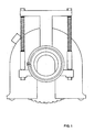
- the guard in accordance with the innovation comprises a pair of parallel walls 1 and 2, interconnected by a side wall 3 in order to constitute a sort of casing open at the bottom which is inserted around tool 4.
- the latter in turn is fitted to shaft 5 of apparatus 6, which in this specific example is a mill.
- Wall 1 is removable, and secured with bolts or the like, so that the tool can be replaced.
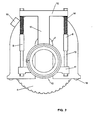
- Figures 1 and 2 illustrate the assembly viewed from wall 2.
- the latter contains an opening 7 designed to allow the tool shaft to slide in relation to the guard.
- a pair of guides 8 is welded to wall 2, allowing the guard to be fitted so that it slides on a support.
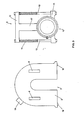
- Support assembly 9 is shown in figure 3.
- Support 9 comprises parts 10 which secure it to the mill.
- Parts 10 are integral with lower arm 11, and support 17 of a second upper arm 12.
- Arms 11 and 12 are connected by the same number of rods 13 secured with nuts, into which helical springs 14 or similar are inserted.
- Rods 13 run inside guides 8, enabling assembly 9 to slide in relation to the guard in constrast with the force exerted by springs 14.
- Securing parts 10 consist of a pair of rings 15 and 16 which are clamped around arm 11 and support 16 with a limited force, allowing the assembly to rotate.
- a pair of idle rollers 18 is fitted at the bottom of the guard, and a connector 19 to allow connection to dust exhausting equipment is fitted at the top of it.
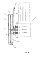
- the guard is used as follows: the assembly is secured to the mill, fitted as in Figure 4; wall 1 is removed and the tool is fitted to shaft 5. The guard is then closed and the apparatus is ready for use.
- springs 14 push the guard downwards so that it continues to surround the tool totally.
- Mill 6 can rotate in relation to the guard inside ring 15, enabling the unit to be gripped in the most convenient way.
- springs or similar return equipment could be incorporated to return the unit to the starting position.
Landscapes
- Engineering & Computer Science (AREA)
- Mechanical Engineering (AREA)
- Life Sciences & Earth Sciences (AREA)
- Wood Science & Technology (AREA)
- Forests & Forestry (AREA)
- Finish Polishing, Edge Sharpening, And Grinding By Specific Grinding Devices (AREA)
- Grinding-Machine Dressing And Accessory Apparatuses (AREA)
Applications Claiming Priority (2)
| Application Number | Priority Date | Filing Date | Title |
|---|---|---|---|
| IT3352288U IT218080Z2 (it) | 1988-10-25 | 1988-10-25 | Carter di protezione per utensili a disco rotante |
| IT3352288U | 1988-10-25 |
Publications (2)
| Publication Number | Publication Date |
|---|---|
| EP0365922A2 true EP0365922A2 (de) | 1990-05-02 |
| EP0365922A3 EP0365922A3 (de) | 1990-08-29 |
Family
ID=11237726
Family Applications (1)
| Application Number | Title | Priority Date | Filing Date |
|---|---|---|---|
| EP89118891A Withdrawn EP0365922A3 (de) | 1988-10-25 | 1989-10-11 | Schutzvorrichtung für rotierende, scheibenförmige Werkzeuge |
Country Status (3)
| Country | Link |
|---|---|
| EP (1) | EP0365922A3 (de) |
| CA (1) | CA2000441A1 (de) |
| IT (1) | IT218080Z2 (de) |
Cited By (6)
| Publication number | Priority date | Publication date | Assignee | Title |
|---|---|---|---|---|
| WO1999042263A1 (de) * | 1998-02-20 | 1999-08-26 | Powertools International Gmbh | Trenngerät |
| EP1059140A2 (de) * | 1999-05-29 | 2000-12-13 | Eberhard Berhalter | Handarbeitsgerät |
| EP1072355A2 (de) * | 1999-07-20 | 2001-01-31 | HILTI Aktiengesellschaft | Sägevorrichtung |
| ES2164554A1 (es) * | 1999-08-30 | 2002-02-16 | Garcia Maria Eugenia Fernandez | Carcasa insonorizada de proteccion en maquinas de disco para el corte de piedras ornamentales. |
| DE102005034446A1 (de) * | 2005-07-23 | 2007-01-25 | Tts Tooltechnic Systems Ag & Co. Kg | Handwerkzeugmaschine, insbesondere Mauerschlitzer, Nutfräse oder Trennschleifer |
| DE102016103151A1 (de) * | 2016-02-23 | 2017-08-24 | Eberhard Berhalter | Werkzeugmaschine |
Citations (5)
| Publication number | Priority date | Publication date | Assignee | Title |
|---|---|---|---|---|
| AT172096B (de) * | 1950-09-02 | 1952-08-11 | Gerda Behrbalk | Vorrichtung zur Herstellung von Mauernuten für Installationszwecke |
| FR1122360A (fr) * | 1955-02-22 | 1956-09-05 | Valbo Stella | Montage de scie circulaire à protecteur amovible pour machines électriques portatives |
| GB1107316A (en) * | 1965-09-02 | 1968-03-27 | Mellor Fred | Improvements in or relating to a guard for a portable tool having a rotatable disc |
| US4022182A (en) * | 1976-01-12 | 1977-05-10 | Lenkevich Steve T | Dust and water confinement unit for portable circular saw |
| DE8624827U1 (de) * | 1986-09-17 | 1987-02-12 | Moehlenkamp, Johannes, 4476 Vrees, De |
-
1988
- 1988-10-25 IT IT3352288U patent/IT218080Z2/it active
-
1989
- 1989-10-11 CA CA 2000441 patent/CA2000441A1/en not_active Abandoned
- 1989-10-11 EP EP89118891A patent/EP0365922A3/de not_active Withdrawn
Patent Citations (5)
| Publication number | Priority date | Publication date | Assignee | Title |
|---|---|---|---|---|
| AT172096B (de) * | 1950-09-02 | 1952-08-11 | Gerda Behrbalk | Vorrichtung zur Herstellung von Mauernuten für Installationszwecke |
| FR1122360A (fr) * | 1955-02-22 | 1956-09-05 | Valbo Stella | Montage de scie circulaire à protecteur amovible pour machines électriques portatives |
| GB1107316A (en) * | 1965-09-02 | 1968-03-27 | Mellor Fred | Improvements in or relating to a guard for a portable tool having a rotatable disc |
| US4022182A (en) * | 1976-01-12 | 1977-05-10 | Lenkevich Steve T | Dust and water confinement unit for portable circular saw |
| DE8624827U1 (de) * | 1986-09-17 | 1987-02-12 | Moehlenkamp, Johannes, 4476 Vrees, De |
Cited By (10)
| Publication number | Priority date | Publication date | Assignee | Title |
|---|---|---|---|---|
| WO1999042263A1 (de) * | 1998-02-20 | 1999-08-26 | Powertools International Gmbh | Trenngerät |
| AT412956B (de) * | 1998-02-20 | 2005-09-26 | Powertools Internat Gmbh | Trenngerät |
| EP1059140A2 (de) * | 1999-05-29 | 2000-12-13 | Eberhard Berhalter | Handarbeitsgerät |
| EP1059140A3 (de) * | 1999-05-29 | 2002-09-11 | Eberhard Berhalter | Handarbeitsgerät |
| EP1072355A2 (de) * | 1999-07-20 | 2001-01-31 | HILTI Aktiengesellschaft | Sägevorrichtung |
| EP1072355A3 (de) * | 1999-07-20 | 2004-02-04 | HILTI Aktiengesellschaft | Sägevorrichtung |
| ES2164554A1 (es) * | 1999-08-30 | 2002-02-16 | Garcia Maria Eugenia Fernandez | Carcasa insonorizada de proteccion en maquinas de disco para el corte de piedras ornamentales. |
| DE102005034446A1 (de) * | 2005-07-23 | 2007-01-25 | Tts Tooltechnic Systems Ag & Co. Kg | Handwerkzeugmaschine, insbesondere Mauerschlitzer, Nutfräse oder Trennschleifer |
| DE102016103151A1 (de) * | 2016-02-23 | 2017-08-24 | Eberhard Berhalter | Werkzeugmaschine |
| EP3210726A1 (de) * | 2016-02-23 | 2017-08-30 | Eberhard Berhalter | Werkzeugmaschine |
Also Published As
| Publication number | Publication date |
|---|---|
| IT8833522V0 (it) | 1988-10-25 |
| EP0365922A3 (de) | 1990-08-29 |
| CA2000441A1 (en) | 1990-04-25 |
| IT218080Z2 (it) | 1992-03-30 |
Similar Documents
| Publication | Publication Date | Title |
|---|---|---|
| US3837383A (en) | Dust collector and safety guard | |
| US3007501A (en) | Combination woodworking machine | |
| ES2044525T3 (es) | Aparato de mano con muela de tronzar o abrasiva. | |
| US3034493A (en) | Suction sawdust collector | |
| GB1334982A (en) | Conditioning grinder | |
| CN212043637U (zh) | 一种工件夹持装置 | |
| EP0365922A2 (de) | Schutzvorrichtung für rotierende, scheibenförmige Werkzeuge | |
| US4192067A (en) | Apparatus for cutting through a tube bundle | |
| US5014542A (en) | Automatic machine tool head designed to increase the number of machine operating axes | |
| SU1111855A1 (ru) | Предохранительное устройство дл шлифовального круга | |
| JPS5810498A (ja) | 紙型の回転断裁装置 | |
| CN209792757U (zh) | 一种手持式切割锯 | |
| EP0358928A3 (de) | Werkzeugmaschine | |
| CN205702678U (zh) | 电圆锯 | |
| CN220560561U (zh) | 一种门窗材料切割防护设备 | |
| CN219426325U (zh) | 一种机械工程零件加工切割设备 | |
| US3264911A (en) | Portable drum flange turning machine | |
| CN213857393U (zh) | 一种铝塑型材集成数控切割锯用定位工装 | |
| EP0038740B1 (de) | Maschine zum Abtrennen von Speisern bei Gussstücken | |
| CN218081785U (zh) | 一种便携的机械加工用刀具打磨装置 | |
| US3176435A (en) | Machine for shaping the end periphery of substantially cylindrical objects | |
| CN219094512U (zh) | 一种立式加工中心防护装置 | |
| CN213004374U (zh) | 一种具有防护装置的砂轮机 | |
| CN216066640U (zh) | 一种机械加工用的防护装置 | |
| CN216940002U (zh) | 一种高安全性的砂轮机 |
Legal Events
| Date | Code | Title | Description |
|---|---|---|---|
| PUAI | Public reference made under article 153(3) epc to a published international application that has entered the european phase |
Free format text: ORIGINAL CODE: 0009012 |
|
| AK | Designated contracting states |
Kind code of ref document: A2 Designated state(s): AT BE CH DE ES FR GB GR LI LU NL SE |
|
| PUAL | Search report despatched |
Free format text: ORIGINAL CODE: 0009013 |
|
| AK | Designated contracting states |
Kind code of ref document: A3 Designated state(s): AT BE CH DE ES FR GB GR LI LU NL SE |
|
| STAA | Information on the status of an ep patent application or granted ep patent |
Free format text: STATUS: THE APPLICATION IS DEEMED TO BE WITHDRAWN |
|
| 18D | Application deemed to be withdrawn |
Effective date: 19910301 |