EP0365922A2 - Guard for rotary disk tools - Google Patents
Guard for rotary disk tools Download PDFInfo
- Publication number
- EP0365922A2 EP0365922A2 EP89118891A EP89118891A EP0365922A2 EP 0365922 A2 EP0365922 A2 EP 0365922A2 EP 89118891 A EP89118891 A EP 89118891A EP 89118891 A EP89118891 A EP 89118891A EP 0365922 A2 EP0365922 A2 EP 0365922A2
- Authority
- EP
- European Patent Office
- Prior art keywords
- guard
- tool
- fact
- fitted
- accordance
- Prior art date
- Legal status (The legal status is an assumption and is not a legal conclusion. Google has not performed a legal analysis and makes no representation as to the accuracy of the status listed.)
- Withdrawn
Links
Images
Classifications
-
- B—PERFORMING OPERATIONS; TRANSPORTING
- B27—WORKING OR PRESERVING WOOD OR SIMILAR MATERIAL; NAILING OR STAPLING MACHINES IN GENERAL
- B27G—ACCESSORY MACHINES OR APPARATUS FOR WORKING WOOD OR SIMILAR MATERIALS; TOOLS FOR WORKING WOOD OR SIMILAR MATERIALS; SAFETY DEVICES FOR WOOD WORKING MACHINES OR TOOLS
- B27G19/00—Safety guards or devices specially adapted for wood saws; Auxiliary devices facilitating proper operation of wood saws
- B27G19/02—Safety guards or devices specially adapted for wood saws; Auxiliary devices facilitating proper operation of wood saws for circular saws
-
- B—PERFORMING OPERATIONS; TRANSPORTING
- B23—MACHINE TOOLS; METAL-WORKING NOT OTHERWISE PROVIDED FOR
- B23Q—DETAILS, COMPONENTS, OR ACCESSORIES FOR MACHINE TOOLS, e.g. ARRANGEMENTS FOR COPYING OR CONTROLLING; MACHINE TOOLS IN GENERAL CHARACTERISED BY THE CONSTRUCTION OF PARTICULAR DETAILS OR COMPONENTS; COMBINATIONS OR ASSOCIATIONS OF METAL-WORKING MACHINES, NOT DIRECTED TO A PARTICULAR RESULT
- B23Q11/00—Accessories fitted to machine tools for keeping tools or parts of the machine in good working condition or for cooling work; Safety devices specially combined with or arranged in, or specially adapted for use in connection with, machine tools
- B23Q11/08—Protective coverings for parts of machine tools; Splash guards
-
- B—PERFORMING OPERATIONS; TRANSPORTING
- B24—GRINDING; POLISHING
- B24B—MACHINES, DEVICES, OR PROCESSES FOR GRINDING OR POLISHING; DRESSING OR CONDITIONING OF ABRADING SURFACES; FEEDING OF GRINDING, POLISHING, OR LAPPING AGENTS
- B24B55/00—Safety devices for grinding or polishing machines; Accessories fitted to grinding or polishing machines for keeping tools or parts of the machine in good working condition
- B24B55/04—Protective covers for the grinding wheel
Definitions
- This innovation relates to a guard designed for rotary disc tools, in particular for portable electric tools such as lapping machines, orbital honing machines, mills, grindwheels and the like.
- the novelty of the innovation lies in the special design and arrangement of the parts, as a result of which the protective element slides in relation to the tool, enabling the latter to penetrate the workpiece to a greater or lesser depth, while the free part remains entirely enclosed by the protective guard.
- the guard in accordance with the innovation therefore constitutes a basic operator safety feature, and in addition is highly practical to use.
- Numerous types of portable cutting equipment use as the tool a disc with the actual tools fitted to the perimeter, which rotates at high speed.
- the protective screen consists of a semi-circular part which covers just over half the tool on one side only.
- Mills used to cut walls are surrounded by a fixed guard, obliging the operator to stop work and adjust its position whenever the cutting depth needs to be altered; equally, this guard only performs its protective function after the tool has wholly penetrated the workpiece, so that any splinters can be expelled freely at the beginning of cutting.
- this innovation offers a guard for rotary disc tools which basically consists of a casing that completely surrounds the tool but is fitted to slide in relation to it.
- the guard can therefore be rested on the part to be cut while the tool is slid for cutting, and the operator remains wholly protected.
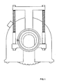
- the guard in accordance with the innovation comprises a pair of parallel walls 1 and 2, interconnected by a side wall 3 in order to constitute a sort of casing open at the bottom which is inserted around tool 4.
- the latter in turn is fitted to shaft 5 of apparatus 6, which in this specific example is a mill.
- Wall 1 is removable, and secured with bolts or the like, so that the tool can be replaced.
- Figures 1 and 2 illustrate the assembly viewed from wall 2.
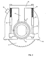
- the latter contains an opening 7 designed to allow the tool shaft to slide in relation to the guard.
- a pair of guides 8 is welded to wall 2, allowing the guard to be fitted so that it slides on a support.
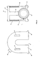
- Support assembly 9 is shown in figure 3.
- Support 9 comprises parts 10 which secure it to the mill.
- Parts 10 are integral with lower arm 11, and support 17 of a second upper arm 12.
- Arms 11 and 12 are connected by the same number of rods 13 secured with nuts, into which helical springs 14 or similar are inserted.
- Rods 13 run inside guides 8, enabling assembly 9 to slide in relation to the guard in constrast with the force exerted by springs 14.
- Securing parts 10 consist of a pair of rings 15 and 16 which are clamped around arm 11 and support 16 with a limited force, allowing the assembly to rotate.
- a pair of idle rollers 18 is fitted at the bottom of the guard, and a connector 19 to allow connection to dust exhausting equipment is fitted at the top of it.
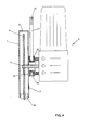
- the guard is used as follows: the assembly is secured to the mill, fitted as in Figure 4; wall 1 is removed and the tool is fitted to shaft 5. The guard is then closed and the apparatus is ready for use.
- springs 14 push the guard downwards so that it continues to surround the tool totally.
- Mill 6 can rotate in relation to the guard inside ring 15, enabling the unit to be gripped in the most convenient way.
- springs or similar return equipment could be incorporated to return the unit to the starting position.
Landscapes
- Engineering & Computer Science (AREA)
- Mechanical Engineering (AREA)
- Life Sciences & Earth Sciences (AREA)
- Wood Science & Technology (AREA)
- Forests & Forestry (AREA)
- Finish Polishing, Edge Sharpening, And Grinding By Specific Grinding Devices (AREA)
- Grinding-Machine Dressing And Accessory Apparatuses (AREA)
Abstract
Guard for rotary disc tools comprising a protective casing which wholly surrounds the tool except for one free side, a support which slides in relation to the said guard, and equipment designed to enable the tool to be fitted on the said support.
Description
- This innovation relates to a guard designed for rotary disc tools, in particular for portable electric tools such as lapping machines, orbital honing machines, mills, grindwheels and the like.
- The novelty of the innovation lies in the special design and arrangement of the parts, as a result of which the protective element slides in relation to the tool, enabling the latter to penetrate the workpiece to a greater or lesser depth, while the free part remains entirely enclosed by the protective guard.
- The guard in accordance with the innovation therefore constitutes a basic operator safety feature, and in addition is highly practical to use.
- Numerous types of portable cutting equipment use as the tool a disc with the actual tools fitted to the perimeter, which rotates at high speed.
- The use of this apparatus involves considerable risk to the operator if the apparatus should get out of control while the tool is still moving, or if the tool breaks during operations, expelling splinters at high speed.
- In addition, splinters and parts of the material removed by the tool always constitute a source of danger.
- For this reason, these types of apparatus are commonly fitted with a protective screen.
- In currently known machines, however, these protective elements are of limited efficacy because in order for the apparatus to be used freely they must be of small size, which reduces their efficacy.
- For example, in the case of orbital honing machines, the protective screen consists of a semi-circular part which covers just over half the tool on one side only.
- Mills used to cut walls are surrounded by a fixed guard, obliging the operator to stop work and adjust its position whenever the cutting depth needs to be altered; equally, this guard only performs its protective function after the tool has wholly penetrated the workpiece, so that any splinters can be expelled freely at the beginning of cutting.
- In order to eliminate these problems, this innovation offers a guard for rotary disc tools which basically consists of a casing that completely surrounds the tool but is fitted to slide in relation to it.
- The guard can therefore be rested on the part to be cut while the tool is slid for cutting, and the operator remains wholly protected.
- This innovation will now be described in detail, with special reference to the annexed figures in which:
- Figures 1 and 2 illustrate the guard in accordance with the innovation, with the tool in the fully retracted position and the working position respectively.
- Figure 3 illustrates the various components of the guard in accordance with the innovation.
- Figure 4 shows a cross-section of a protective device in accordance with the innovation, applied to a mill.
- The guard in accordance with the innovation comprises a pair of
parallel walls tool 4. The latter in turn is fitted toshaft 5 of apparatus 6, which in this specific example is a mill. -
Wall 1 is removable, and secured with bolts or the like, so that the tool can be replaced. - Figures 1 and 2 illustrate the assembly viewed from
wall 2. - The latter contains an opening 7 designed to allow the tool shaft to slide in relation to the guard.
- A pair of
guides 8 is welded towall 2, allowing the guard to be fitted so that it slides on a support. Support assembly 9 is shown in figure 3. - Support 9 comprises
parts 10 which secure it to the mill. -
Parts 10 are integral withlower arm 11, and support 17 of a secondupper arm 12. -
Arms rods 13 secured with nuts, into whichhelical springs 14 or similar are inserted. -
Rods 13 run insideguides 8, enabling assembly 9 to slide in relation to the guard in constrast with the force exerted bysprings 14. - Securing
parts 10 consist of a pair ofrings arm 11 and support 16 with a limited force, allowing the assembly to rotate. - A pair of
idle rollers 18 is fitted at the bottom of the guard, and aconnector 19 to allow connection to dust exhausting equipment is fitted at the top of it. - The guard is used as follows: the assembly is secured to the mill, fitted as in Figure 4;
wall 1 is removed and the tool is fitted toshaft 5. The guard is then closed and the apparatus is ready for use. - Supppose, for example, that a wall needs to be cut. Normally the relative positions of the various parts are those shown in figures 1 and 4, with assembly 9 fully raised by
springs 14 and the tool wholly inside the guard. -
Rollers 18 are then rested on the wall to be cut, the motor is started and cutting is begun by pushing the tool downwards; the tool slides in relation to the guard together with assembly 9 until exiting from it. This situation is illustrated in Figure 2. - Cutting then proceeds, with
rollers 10 enabling the assembly to slide easily along the wall. - During all these stages the tool remains wholly protected inside the guard, eliminating all operator risk.
- When cutting is completed and the assembly is detached from the wall,
springs 14 push the guard downwards so that it continues to surround the tool totally. - Mill 6 can rotate in relation to the guard inside
ring 15, enabling the unit to be gripped in the most convenient way. - If required, springs or similar return equipment could be incorporated to return the unit to the starting position.
- The size and the materials used can obviously be varied in accordance with the required use.
Claims (7)
1. Guard for rotary disc tools of the type comprising a casing which wholly surrounds the tool except for one side, characterised by the fact that it contains systems designed to enable the said tool to slide in relation to the said guard and exit at the said free side.
2. Guard for rotary disc tools comprising a protective casing which wholly surrounds the tool except for one free side, a support which slides in relation to the said guard and equipment designed to allow the tool to be fitted to the said support.
3. Guard in accordance with claim 2, characterised by the fact that it comprises flexible equipment to return the said support.
4. Guard in accordance with claim 2 or 3, characterised by the fact that two or more idle rollers are fitted at the said free side to allow the assembly to slide during the work.
5. Guard in accordance with claim 2, characterised by the fact that it includes a connector to allow connection to dust exhausting equipment.
6. Guard for rotary disc tools characterised by the fact that it includes:
- a casing which wholly surrounds the tool except for one free side
- a pair of guides integral with the said casing
- a framework fitted with equipment designed to allow the tool drive apparatus to be fitted; the said framework is designed to slide along the said guides, moving from a position in which the tool is wholly enclosed within the guard to a position in which the tool projects through the said free side.
7. Guard in accordance with claim 5, characterised by the fact that it includes flexible equipment designed to return the tool inside the guard.
Applications Claiming Priority (2)
| Application Number | Priority Date | Filing Date | Title |
|---|---|---|---|
| IT3352288U | 1988-10-25 | ||
| IT3352288U IT218080Z2 (en) | 1988-10-25 | 1988-10-25 | CARTER OF PROTECTION FOR TOOLS WITH ROTATING DISC |
Publications (2)
| Publication Number | Publication Date |
|---|---|
| EP0365922A2 true EP0365922A2 (en) | 1990-05-02 |
| EP0365922A3 EP0365922A3 (en) | 1990-08-29 |
Family
ID=11237726
Family Applications (1)
| Application Number | Title | Priority Date | Filing Date |
|---|---|---|---|
| EP89118891A Withdrawn EP0365922A3 (en) | 1988-10-25 | 1989-10-11 | Guard for rotary disk tools |
Country Status (3)
| Country | Link |
|---|---|
| EP (1) | EP0365922A3 (en) |
| CA (1) | CA2000441A1 (en) |
| IT (1) | IT218080Z2 (en) |
Cited By (6)
| Publication number | Priority date | Publication date | Assignee | Title |
|---|---|---|---|---|
| WO1999042263A1 (en) * | 1998-02-20 | 1999-08-26 | Powertools International Gmbh | Cutting-off apparatus |
| EP1059140A2 (en) * | 1999-05-29 | 2000-12-13 | Eberhard Berhalter | Hand tool |
| EP1072355A2 (en) * | 1999-07-20 | 2001-01-31 | HILTI Aktiengesellschaft | Sawing device |
| ES2164554A1 (en) * | 1999-08-30 | 2002-02-16 | Garcia Maria Eugenia Fernandez | Disk machine protection soundproof casing for cutting ornamental stones |
| DE102005034446A1 (en) * | 2005-07-23 | 2007-01-25 | Tts Tooltechnic Systems Ag & Co. Kg | Hand-operated machine tool for milling and grinding has protective dust-suction hood fitting over workpiece and over vertically movable machine unit which can pivot relative to hood |
| DE102016103151A1 (en) * | 2016-02-23 | 2017-08-24 | Eberhard Berhalter | machine tool |
Citations (5)
| Publication number | Priority date | Publication date | Assignee | Title |
|---|---|---|---|---|
| AT172096B (en) * | 1950-09-02 | 1952-08-11 | Gerda Behrbalk | Device for making wall grooves for installation purposes |
| FR1122360A (en) * | 1955-02-22 | 1956-09-05 | Valbo Stella | Circular saw assembly with removable guard for portable electric machines |
| GB1107316A (en) * | 1965-09-02 | 1968-03-27 | Mellor Fred | Improvements in or relating to a guard for a portable tool having a rotatable disc |
| US4022182A (en) * | 1976-01-12 | 1977-05-10 | Lenkevich Steve T | Dust and water confinement unit for portable circular saw |
| DE8624827U1 (en) * | 1986-09-17 | 1987-02-12 | Möhlenkamp, Johannes, 4476 Vrees | Hand-operated chainsaw |
-
1988
- 1988-10-25 IT IT3352288U patent/IT218080Z2/en active
-
1989
- 1989-10-11 CA CA 2000441 patent/CA2000441A1/en not_active Abandoned
- 1989-10-11 EP EP89118891A patent/EP0365922A3/en not_active Withdrawn
Patent Citations (5)
| Publication number | Priority date | Publication date | Assignee | Title |
|---|---|---|---|---|
| AT172096B (en) * | 1950-09-02 | 1952-08-11 | Gerda Behrbalk | Device for making wall grooves for installation purposes |
| FR1122360A (en) * | 1955-02-22 | 1956-09-05 | Valbo Stella | Circular saw assembly with removable guard for portable electric machines |
| GB1107316A (en) * | 1965-09-02 | 1968-03-27 | Mellor Fred | Improvements in or relating to a guard for a portable tool having a rotatable disc |
| US4022182A (en) * | 1976-01-12 | 1977-05-10 | Lenkevich Steve T | Dust and water confinement unit for portable circular saw |
| DE8624827U1 (en) * | 1986-09-17 | 1987-02-12 | Möhlenkamp, Johannes, 4476 Vrees | Hand-operated chainsaw |
Cited By (10)
| Publication number | Priority date | Publication date | Assignee | Title |
|---|---|---|---|---|
| WO1999042263A1 (en) * | 1998-02-20 | 1999-08-26 | Powertools International Gmbh | Cutting-off apparatus |
| AT412956B (en) * | 1998-02-20 | 2005-09-26 | Powertools Internat Gmbh | SEPARATION DEVICE |
| EP1059140A2 (en) * | 1999-05-29 | 2000-12-13 | Eberhard Berhalter | Hand tool |
| EP1059140A3 (en) * | 1999-05-29 | 2002-09-11 | Eberhard Berhalter | Hand tool |
| EP1072355A2 (en) * | 1999-07-20 | 2001-01-31 | HILTI Aktiengesellschaft | Sawing device |
| EP1072355A3 (en) * | 1999-07-20 | 2004-02-04 | HILTI Aktiengesellschaft | Sawing device |
| ES2164554A1 (en) * | 1999-08-30 | 2002-02-16 | Garcia Maria Eugenia Fernandez | Disk machine protection soundproof casing for cutting ornamental stones |
| DE102005034446A1 (en) * | 2005-07-23 | 2007-01-25 | Tts Tooltechnic Systems Ag & Co. Kg | Hand-operated machine tool for milling and grinding has protective dust-suction hood fitting over workpiece and over vertically movable machine unit which can pivot relative to hood |
| DE102016103151A1 (en) * | 2016-02-23 | 2017-08-24 | Eberhard Berhalter | machine tool |
| EP3210726A1 (en) * | 2016-02-23 | 2017-08-30 | Eberhard Berhalter | Power tool |
Also Published As
| Publication number | Publication date |
|---|---|
| CA2000441A1 (en) | 1990-04-25 |
| IT8833522V0 (en) | 1988-10-25 |
| EP0365922A3 (en) | 1990-08-29 |
| IT218080Z2 (en) | 1992-03-30 |
Similar Documents
| Publication | Publication Date | Title |
|---|---|---|
| US3007501A (en) | Combination woodworking machine | |
| ES2044525T3 (en) | HAND APPARATUS WITH CUTTING OR ABRASIVE WHEEL. | |
| US3034493A (en) | Suction sawdust collector | |
| GB1334982A (en) | Conditioning grinder | |
| CN212043637U (en) | Workpiece clamping device | |
| EP0365922A2 (en) | Guard for rotary disk tools | |
| US4192067A (en) | Apparatus for cutting through a tube bundle | |
| US5014542A (en) | Automatic machine tool head designed to increase the number of machine operating axes | |
| KR910015354A (en) | Apparatus for performing cutting and roller polishing operations on workpieces | |
| US3939749A (en) | Band saw | |
| CN117140219B (en) | Motor housing processingequipment with function of polishing | |
| SU1111855A1 (en) | Grinding wheel protective device | |
| CN215281125U (en) | Cutting device with protection function | |
| JPS5810498A (en) | Rotary cutter for paper pattern | |
| CN205702678U (en) | Electrotrephine | |
| CN209792757U (en) | hand-held type slitting saw | |
| CN209364729U (en) | A kind of guillotine | |
| EP0358928A3 (en) | Machine-tool | |
| CN220560561U (en) | Door and window material cutting protective equipment | |
| CN219426325U (en) | Machining and cutting equipment for mechanical engineering parts | |
| CN114800153B (en) | Device for preventing waste material from splashing in metal grinding | |
| CN213857393U (en) | Positioning tool for integrated numerical control cutting saw of aluminum-plastic profile | |
| CN221365088U (en) | Safety protection device based on band saw | |
| EP0038740B1 (en) | Device for removing risers from castings | |
| CN220638112U (en) | Trimming equipment with dust removal structure |
Legal Events
| Date | Code | Title | Description |
|---|---|---|---|
| PUAI | Public reference made under article 153(3) epc to a published international application that has entered the european phase |
Free format text: ORIGINAL CODE: 0009012 |
|
| AK | Designated contracting states |
Kind code of ref document: A2 Designated state(s): AT BE CH DE ES FR GB GR LI LU NL SE |
|
| PUAL | Search report despatched |
Free format text: ORIGINAL CODE: 0009013 |
|
| AK | Designated contracting states |
Kind code of ref document: A3 Designated state(s): AT BE CH DE ES FR GB GR LI LU NL SE |
|
| STAA | Information on the status of an ep patent application or granted ep patent |
Free format text: STATUS: THE APPLICATION IS DEEMED TO BE WITHDRAWN |
|
| 18D | Application deemed to be withdrawn |
Effective date: 19910301 |