EP0365739A1 - Gasgenerator - Google Patents
Gasgenerator Download PDFInfo
- Publication number
- EP0365739A1 EP0365739A1 EP89107125A EP89107125A EP0365739A1 EP 0365739 A1 EP0365739 A1 EP 0365739A1 EP 89107125 A EP89107125 A EP 89107125A EP 89107125 A EP89107125 A EP 89107125A EP 0365739 A1 EP0365739 A1 EP 0365739A1
- Authority
- EP
- European Patent Office
- Prior art keywords
- fuel
- combustion chamber
- openings
- gas generator
- ignition
- Prior art date
- Legal status (The legal status is an assumption and is not a legal conclusion. Google has not performed a legal analysis and makes no representation as to the accuracy of the status listed.)
- Withdrawn
Links
Images
Classifications
-
- B—PERFORMING OPERATIONS; TRANSPORTING
- B60—VEHICLES IN GENERAL
- B60R—VEHICLES, VEHICLE FITTINGS, OR VEHICLE PARTS, NOT OTHERWISE PROVIDED FOR
- B60R21/00—Arrangements or fittings on vehicles for protecting or preventing injuries to occupants or pedestrians in case of accidents or other traffic risks
- B60R21/02—Occupant safety arrangements or fittings, e.g. crash pads
- B60R21/16—Inflatable occupant restraints or confinements designed to inflate upon impact or impending impact, e.g. air bags
- B60R21/26—Inflatable occupant restraints or confinements designed to inflate upon impact or impending impact, e.g. air bags characterised by the inflation fluid source or means to control inflation fluid flow
- B60R21/264—Inflatable occupant restraints or confinements designed to inflate upon impact or impending impact, e.g. air bags characterised by the inflation fluid source or means to control inflation fluid flow using instantaneous generation of gas, e.g. pyrotechnic
- B60R21/2644—Inflatable occupant restraints or confinements designed to inflate upon impact or impending impact, e.g. air bags characterised by the inflation fluid source or means to control inflation fluid flow using instantaneous generation of gas, e.g. pyrotechnic using only solid reacting substances, e.g. pellets, powder
- B60R2021/2648—Inflatable occupant restraints or confinements designed to inflate upon impact or impending impact, e.g. air bags characterised by the inflation fluid source or means to control inflation fluid flow using instantaneous generation of gas, e.g. pyrotechnic using only solid reacting substances, e.g. pellets, powder comprising a plurality of combustion chambers or sub-chambers
Definitions
- the invention relates to the inflatable protective cushion of an impact protection system for vehicle occupants (airbag) according to the preamble of claim 1.
- a gas generator which has two combustion chambers filled with fuel, each of which is provided with its own gas outlet to the protective cushion. Part of the gas generated by the fuel in the first combustion chamber is thus passed directly into the protective cushion, the remaining part of the propellant gases of the fuel in the first combustion chamber igniting the fuel in the second combustion chamber in order to fully inflate the protective cushion.
- the load on the protective cushion is to be reduced and an excessively high, i.e. H. if necessary, sound pressure leading to hearing damage can be prevented.
- the object of the invention is to provide a gas generator in which no injuries occur even in the event of a possible "out-of-position", and with a relatively low production cost, the gas generator being easily adaptable to the respective application, such as vehicle type, etc. should be.
- the propellant gas is initially generated only by the first fuel part, reaches the second fuel part via the passage openings on or in the sheet metal insert, and from there via the passage openings from the combustion chamber into the filter chamber and from the filter chamber finally into the protective cushion .
- the gas volume released by the first fuel part is controlled so that a person, in particular a child, who should be in front of an airbag, is gently pressed into the seat.
- the propellant gases generated by the first fuel part on their way from the opening between the first and second fuel parts to the transfer openings into the filter chamber ignite the second, larger quantity of fuel part, which suddenly releases a large amount of propellant gas, which the protective cushion inflates completely in no time and protects the occupant who is normally seated from accident injuries.
- the decisive advantage of the invention is that it can be used without significant changes in the existing, mature and already mass-produced gas generators, for example in a gas generator according to DE-OS 29 15 202.
- Another advantage of the invention is its simplicity , ie the existing airbag gas generators from series production only need to be provided with the insert plate in the combustion chamber.
- the two processes can be controlled by simple measures, in particular by arranging the sheet metal insert in the combustion chamber, i.e. for example the ratio of the quantities of the first fuel part to the second fuel part, the cross section the opening between the two fuel parts, the diameters of the pellets and the like.
- the gas generator according to the invention can be easily adapted to the respective conditions, for example the respective vehicle type, that is to say, for. B. according to the respective crumple zone and the interior of the car.
- a conventional gas generator is partially reproduced, as can be seen, for example, from DE-OS 29 15 202.
- An ignition device 2 is then arranged in a central chamber 1 closed at the top.
- a toroidal combustion chamber 3 extends in a housing 4 concentrically to the central axis A-A and a filter chamber 6 extends around the combustion chamber 3 in a housing 5.
- the combustion chamber housing 4 is provided on its inner circumferential wall 7 facing the central chamber 1 with ignition openings 8 through which the hot ignition gases enter the combustion chamber 3 from the central chamber 1.
- the combustion chamber 3 is divided into two sections by a tubular sheet metal insert 9 arranged concentrically with the central axis AA, each of the two sections being filled with a solid fuel in the form of pellets, namely the section between the sheet insert 9 and the inner peripheral wall 7 of the combustion chamber housing 4 a first part 10 of the fuel and the section between the sheet metal insert 9 and the outer peripheral wall 11 of the combustion chamber housing 4 with a second part 12 of the fuel.
- the amount of fuel in the second part 12 is greater than the amount in the first part 10.
- the fuel 10, 12 is covered at the top by a cover 13 in order to fix it and thus prevent, for example, shaking noises.
- the sheet metal insert 9 is on one, d. H. 1 at its lower end provided with openings 14, whereby the propellant gases generated by the first part 10 of the fuel can pass to the second part 12 of the fuel in the other separation chamber section according to the arrow P.
- the ignition openings 8 are in contrast in the upper Area of the combustion chamber 3 is provided. They are therefore opposite the end region of the sheet metal insert 9 facing away from the passage openings 14.
- the outer peripheral wall 11 of the combustion chamber housing 4 is provided with openings 15, through which the propellant gas enters the filter chamber 6 from the combustion chamber 3.
- a screen or filter 16 is arranged in front of the transfer openings 15.
- the transition openings 15 are offset from the ignition openings 8 in the axial direction, with respect to the central axis A-A, to the center of the combustion chamber 3. From the filter chamber 6, in which the hot particles are retained in the propellant gas, the propellant gas flows through openings, not shown in the drawing, into the folded protective cushion, likewise not shown in the drawing, which covers the gas generator at the top.
- the gas generator When the gas generator is triggered, only the first part 10 of the fuel is fired by the ignition device 2 via the ignition openings 8, so that the protective cushion is initially inflated only as much becomes that a person in the vehicle immediately in front of the airbag is gently pressed into the seat.
- the propellant gas generated by the first part 10 of the fuel ignites the second part 12 of the fuel, which is present in a relatively large amount, as it passes from the passage opening 14 in the sheet metal insert 9 to the transfer openings 15. This results in a steep increase in propellant gas production and thus a complete filling of the protective cushion in a relatively short time.
- the embodiment of Fig. 1 has u. a. the advantage that the fuel 10, 12 can be filled into the combustion chamber 3 relatively easily.
- the embodiment of FIG. 2 differs from that of FIG. 1 essentially in that the ignition openings 17 are offset axially towards the center and the sheet metal insert 18 is plate-shaped, i. H. has an outer portion 19 which is essentially radial with respect to the main axis A-A and extends over a crank 20 to the inner peripheral wall 7 of the combustion chamber housing 4.
- a first upper fuel part 21 is formed, which is fired by the ignition gas of the ignition device 2 via the ignition openings 8.
- the opening 23 between the first upper fuel part 21 and the second lower fuel part 22 is formed by a gap between the sheet metal insert 18 and the outer peripheral wall 11 of the combustion chamber housing 4.
- the insert plate 18 can be designed as an easily manufactured stamped part.
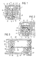
- the central chamber with the ignition device 27 is formed by a tube 26 which is closed at the top and which is arranged in the middle with respect to the longitudinal direction of the tube 24 and extends transversely from below into the interior of the tube 24, i. H. the combustion chamber 28 extends.
- the combustion chamber 28 is subdivided by a sheet metal insert 29 arranged parallel to the tube axis 25, specifically into a first fuel part 30 and a second fuel part 31.
- the combustion chamber 28 is closed off from the outside by a cover 32 with through openings 33 to the filter chamber 34.
- the first part 30 of the fuel is thus located in the area of the combustion chamber 28 adjacent to the ignition openings 35, that is to say in the section which is delimited by the tube 26 with the ignition device 27 and the ignition openings, the sheet metal insert 29 and the cover 32.
- a gap between the cover 32 and the sheet metal insert 29 creates an opening 36 between the two fuel parts 30, 31.
- a sieve or filter 37 is arranged in front of the passage opening 33 from the combustion chamber 28 in the filter chamber 34.
Landscapes
- Engineering & Computer Science (AREA)
- Mechanical Engineering (AREA)
- Physics & Mathematics (AREA)
- Fluid Mechanics (AREA)
- Air Bags (AREA)
- Feeding, Discharge, Calcimining, Fusing, And Gas-Generation Devices (AREA)
Applications Claiming Priority (2)
| Application Number | Priority Date | Filing Date | Title |
|---|---|---|---|
| DE3835356A DE3835356A1 (de) | 1988-10-17 | 1988-10-17 | Gasgenerator |
| DE3835356 | 1988-10-17 |
Publications (1)
| Publication Number | Publication Date |
|---|---|
| EP0365739A1 true EP0365739A1 (de) | 1990-05-02 |
Family
ID=6365316
Family Applications (1)
| Application Number | Title | Priority Date | Filing Date |
|---|---|---|---|
| EP89107125A Withdrawn EP0365739A1 (de) | 1988-10-17 | 1989-04-20 | Gasgenerator |
Country Status (6)
| Country | Link |
|---|---|
| US (1) | US5009855A (ja) |
| EP (1) | EP0365739A1 (ja) |
| JP (1) | JPH02169347A (ja) |
| KR (1) | KR900006182A (ja) |
| CA (1) | CA2000797A1 (ja) |
| DE (1) | DE3835356A1 (ja) |
Cited By (8)
| Publication number | Priority date | Publication date | Assignee | Title |
|---|---|---|---|---|
| EP0451731A2 (de) * | 1990-04-09 | 1991-10-16 | Alfred Kroiss | Gaskissen-Aufprallschutzvorrichtung |
| AU626063B1 (en) * | 1990-03-26 | 1992-07-23 | Morton International, Inc. | Two-stage automotive gas bag inflator using igniter material to delay second stage ignition |
| DE19709597A1 (de) * | 1997-03-08 | 1998-09-17 | Temic Bayern Chem Airbag Gmbh | Vorrichtung zur Arretierung von Brennstoffgranulat in Brennkammern |
| US6364354B1 (en) | 1998-09-28 | 2002-04-02 | Daicel Chemical Industries, Ltd. | Air bag gas generator and air bag apparatus |
| US6460884B1 (en) | 1998-09-28 | 2002-10-08 | Daicel Chemical Industries, Ltd. | Air bag gas generator and air bag apparatus |
| US6491321B1 (en) | 1999-02-16 | 2002-12-10 | Daicel Chemical Industries, Ltd. | Multistage gas generator for air bag and air bag apparatus |
| US6547275B2 (en) | 1998-11-30 | 2003-04-15 | Daicel Chemical Industries, Ltd. | Air bag gas generator and air bag device |
| US6547278B2 (en) | 1997-03-08 | 2003-04-15 | Trw Airbag Systems Gmbh & Co. Kg | Gas generator for a safety arrangement |
Families Citing this family (25)
| Publication number | Priority date | Publication date | Assignee | Title |
|---|---|---|---|---|
| US4943086A (en) * | 1989-06-30 | 1990-07-24 | Morton Thiokol, Inc. | Gas bag inflator with a two welded joint housing |
| US5397543A (en) * | 1993-06-21 | 1995-03-14 | Automotive Systems Laboratory, Inc. | Gas generator |
| US5345875A (en) * | 1993-07-07 | 1994-09-13 | Automotive Systems Laboratory, Inc. | Gas generator |
| US5531474A (en) * | 1994-04-26 | 1996-07-02 | Breed Automotive Technology, Inc. | Inflator assembly |
| US5460405A (en) * | 1994-06-28 | 1995-10-24 | Trw Vehicle Safety Systems Inc. | Apparatus for inflating an inflatable vehicle occupant restraint |
| US5551723A (en) * | 1994-07-20 | 1996-09-03 | Breed Automotive Technology, Inc. | Pulse shaping for airbag inflators |
| US5628528A (en) * | 1995-07-06 | 1997-05-13 | Automotive Systems Laboratory, Inc. | Dual chamber nonazide gas generator |
| US5622380A (en) * | 1995-09-21 | 1997-04-22 | Automotive Systems Laboratory, Inc. | Variable nonazide gas generator having multiple propellant chambers |
| DE19543796B4 (de) * | 1995-11-24 | 2004-11-25 | Temic Bayern-Chemie Airbag Gmbh | Gasgenerator für ein Airbagsystem |
| US5611567A (en) * | 1995-12-18 | 1997-03-18 | Cartridge Actuated Devices, Inc. | Non-explosive linear release device |
| US5844164A (en) * | 1996-02-23 | 1998-12-01 | Breed Automotive Technologies, Inc. | Gas generating device with specific composition |
| US5829785A (en) * | 1996-03-26 | 1998-11-03 | Morton International, Inc. | Internal structure for a two-walled inflator |
| DE19620758A1 (de) * | 1996-05-23 | 1997-11-27 | Temic Bayern Chem Airbag Gmbh | Gasgenerator |
| US5808232A (en) * | 1996-11-13 | 1998-09-15 | Automotive Systems Laboratory, Inc. | Gas inflator having aluminum or alumina bead filter |
| US5700973A (en) * | 1996-11-13 | 1997-12-23 | Automotive Systems Laboratory, Inc. | Gas inflator having aluminum bead filter |
| US5738373A (en) * | 1996-11-13 | 1998-04-14 | Automotive Systems Laboratory, Inc. | Gas inflator with ceramic foam balls |
| US5806888A (en) * | 1997-01-16 | 1998-09-15 | Automotive Systems Laboratory, Inc. | Air bag inflator |
| US5944343A (en) * | 1997-08-21 | 1999-08-31 | Automotive Systems Laboratory, Inc. | Miniature inflator |
| EP1089820B1 (en) * | 1998-04-28 | 2007-11-21 | Basf Catalysts Llc | Monolithic catalysts and related process for manufacture |
| EP1487676A2 (en) * | 2002-03-26 | 2004-12-22 | Automotive Systems Laboratory, Inc. | Multiple chamber dual stage inflator |
| US7665764B2 (en) | 2004-01-15 | 2010-02-23 | Daicel Chemical Industries, Ltd. | Gas generator for air bag |
| JP4494023B2 (ja) * | 2004-01-15 | 2010-06-30 | ダイセル化学工業株式会社 | エアバッグ用ガス発生器 |
| EP2315693A1 (de) * | 2008-08-12 | 2011-05-04 | Webasto AG | Fahrzeugflächenbauteil mit solarzellenanordnung |
| US8556294B1 (en) | 2012-08-22 | 2013-10-15 | Key Safety Systems, Inc | Airbag inflator |
| JP6009997B2 (ja) | 2013-06-21 | 2016-10-19 | 株式会社ダイセル | 人員拘束装置用ガス発生器 |
Citations (3)
| Publication number | Priority date | Publication date | Assignee | Title |
|---|---|---|---|---|
| DE2224201A1 (de) * | 1972-05-18 | 1973-11-29 | Bayern Chemie Gmbh Flugchemie | Feststoffgasgenerator |
| FR2188536A5 (ja) * | 1972-06-07 | 1974-01-18 | Allied Chem | |
| DE2915202A1 (de) * | 1979-04-14 | 1980-10-16 | Bayern Chemie Gmbh Flugchemie | Gasgenerator in blechbauweise |
Family Cites Families (5)
| Publication number | Priority date | Publication date | Assignee | Title |
|---|---|---|---|---|
| US3532358A (en) * | 1968-07-22 | 1970-10-06 | Chrysler Corp | Inflatable device |
| US3711115A (en) * | 1970-11-24 | 1973-01-16 | Allied Chem | Pyrotechnic gas generator |
| US3961806A (en) * | 1972-02-04 | 1976-06-08 | Rocket Research Corporation | Two stage inflation system |
| US3972545A (en) * | 1975-03-10 | 1976-08-03 | Thiokol Corporation | Multi-level cool gas generator |
| US4358998A (en) * | 1980-02-04 | 1982-11-16 | Thiokol Corporation | Igniter for a pyrotechnic gas bag inflator |
-
1988
- 1988-10-17 DE DE3835356A patent/DE3835356A1/de not_active Ceased
-
1989
- 1989-04-20 EP EP89107125A patent/EP0365739A1/de not_active Withdrawn
- 1989-05-30 KR KR1019890007206A patent/KR900006182A/ko not_active Application Discontinuation
- 1989-10-16 CA CA002000797A patent/CA2000797A1/en not_active Abandoned
- 1989-10-17 JP JP1268307A patent/JPH02169347A/ja active Pending
- 1989-10-17 US US07/422,649 patent/US5009855A/en not_active Expired - Lifetime
Patent Citations (3)
| Publication number | Priority date | Publication date | Assignee | Title |
|---|---|---|---|---|
| DE2224201A1 (de) * | 1972-05-18 | 1973-11-29 | Bayern Chemie Gmbh Flugchemie | Feststoffgasgenerator |
| FR2188536A5 (ja) * | 1972-06-07 | 1974-01-18 | Allied Chem | |
| DE2915202A1 (de) * | 1979-04-14 | 1980-10-16 | Bayern Chemie Gmbh Flugchemie | Gasgenerator in blechbauweise |
Cited By (17)
| Publication number | Priority date | Publication date | Assignee | Title |
|---|---|---|---|---|
| AU626063B1 (en) * | 1990-03-26 | 1992-07-23 | Morton International, Inc. | Two-stage automotive gas bag inflator using igniter material to delay second stage ignition |
| EP0451731A2 (de) * | 1990-04-09 | 1991-10-16 | Alfred Kroiss | Gaskissen-Aufprallschutzvorrichtung |
| EP0451731A3 (en) * | 1990-04-09 | 1992-07-15 | Alfred Kroiss | Air bag protection device |
| US6547278B2 (en) | 1997-03-08 | 2003-04-15 | Trw Airbag Systems Gmbh & Co. Kg | Gas generator for a safety arrangement |
| US6250673B1 (en) | 1997-03-08 | 2001-06-26 | Trw Airbag Systems Gmbh & Co. Kg | Gas generator for a safety device |
| DE19709597A1 (de) * | 1997-03-08 | 1998-09-17 | Temic Bayern Chem Airbag Gmbh | Vorrichtung zur Arretierung von Brennstoffgranulat in Brennkammern |
| US6491320B1 (en) | 1998-09-28 | 2002-12-10 | Daicel Chemical Industries, Ltd. | Air bag gas generator and air bag apparatus |
| US6460884B1 (en) | 1998-09-28 | 2002-10-08 | Daicel Chemical Industries, Ltd. | Air bag gas generator and air bag apparatus |
| US6460883B1 (en) | 1998-09-28 | 2002-10-08 | Daicel Chemical Industries, Ltd. | Air bag gas generator and air bag apparatus |
| US6412815B1 (en) | 1998-09-28 | 2002-07-02 | Daicel Chemical Industries, Ltd. | Gas generator for air bag and air bag device |
| US6364354B1 (en) | 1998-09-28 | 2002-04-02 | Daicel Chemical Industries, Ltd. | Air bag gas generator and air bag apparatus |
| US6557888B1 (en) | 1998-09-28 | 2003-05-06 | Daicel Chemical Industries, Ltd. | Air bag gas generator and air bag apparatus |
| US6547275B2 (en) | 1998-11-30 | 2003-04-15 | Daicel Chemical Industries, Ltd. | Air bag gas generator and air bag device |
| US6598901B2 (en) | 1998-11-30 | 2003-07-29 | Daicel Chemical Industries, Ltd. | Gas generator for air bag and air bag apparatus |
| US6491321B1 (en) | 1999-02-16 | 2002-12-10 | Daicel Chemical Industries, Ltd. | Multistage gas generator for air bag and air bag apparatus |
| US6669230B1 (en) | 1999-02-16 | 2003-12-30 | Daicel Chemical Industries, Ltd. | Multistage gas generator for air bag and air bag apparatus |
| US6722694B1 (en) | 1999-02-16 | 2004-04-20 | Daicel Chemical Industries, Ltd. | Gas generator for multi-stage air bag and air bag device |
Also Published As
| Publication number | Publication date |
|---|---|
| CA2000797A1 (en) | 1990-04-17 |
| KR900006182A (ko) | 1990-05-07 |
| US5009855A (en) | 1991-04-23 |
| JPH02169347A (ja) | 1990-06-29 |
| DE3835356A1 (de) | 1990-04-19 |
Similar Documents
| Publication | Publication Date | Title |
|---|---|---|
| EP0365739A1 (de) | Gasgenerator | |
| DE19846185B4 (de) | Pyrotechnische Gassackaufblasvorrichtung | |
| DE69934673T2 (de) | Aufblasvorrichtung mit adaptativem gassfluss | |
| DE69624112T2 (de) | Azidfreier zweikammer-generator | |
| DE69617199T2 (de) | Variabler azidfreier gasgenerator mit mehreren treibstoffkammern | |
| DE69611314T2 (de) | Mehrstufiges Luftsack-Aufblassystem | |
| DE19812221B4 (de) | Airbagaufblasvorrichtung mit Druckregulierung | |
| DE60026969T2 (de) | Gasgenerator | |
| EP1753643B1 (de) | Fahrzeugsitz-einheit | |
| DE60006886T2 (de) | Airbagvorrichtung | |
| DE10102597B4 (de) | Sicherheitseinrichtung an einem Kraftfahrzeug zum Schutz von Fußgängern | |
| DE69608472T2 (de) | Airbagmodul mit zylindrischem Aufbau | |
| DE69004354T2 (de) | Gassack-Aufprallschutzvorrichtung. | |
| DE69620114T2 (de) | Unabhängiger,pyrotechnischer Zünder für eine Aufblasvorrichtung | |
| DE60012046T2 (de) | Metallischer luftsack | |
| DE29713112U1 (de) | Gassack-Rückhaltesystem | |
| DE4005768A1 (de) | Gasgenerator | |
| DE29805209U1 (de) | Aufprall-Schutzvorrichtung für Fahrzeuginsassen | |
| WO2021048117A1 (de) | Gassackmodul und fahrzeugsitz und fahrzeuginsassen-schutzsystem | |
| EP0932526B1 (de) | Verfahren zur sicherung eines fahrzeuginsassen und airbagmodul zur durchführung des verfahrens | |
| DE10020929C5 (de) | Airbagmodul | |
| DE4121039A1 (de) | Gasgenerator in blechbauweise als teil einer aufprallschutzeinrichtung | |
| DE60302554T2 (de) | Gasgenerator | |
| EP1113949B1 (de) | Airbagmodul mit mehrstufigem Gasgenerator | |
| DE69506192T2 (de) | Regeldurchlass für das Inflatorgas eines Gaskissens |
Legal Events
| Date | Code | Title | Description |
|---|---|---|---|
| PUAI | Public reference made under article 153(3) epc to a published international application that has entered the european phase |
Free format text: ORIGINAL CODE: 0009012 |
|
| AK | Designated contracting states |
Kind code of ref document: A1 Designated state(s): DE FR GB IT SE |
|
| 17P | Request for examination filed |
Effective date: 19900503 |
|
| STAA | Information on the status of an ep patent application or granted ep patent |
Free format text: STATUS: THE APPLICATION IS DEEMED TO BE WITHDRAWN |
|
| 18D | Application deemed to be withdrawn |
Effective date: 19911105 |