EP0365078A1 - Ständer für elektrische Bügeleisen - Google Patents
Ständer für elektrische Bügeleisen Download PDFInfo
- Publication number
- EP0365078A1 EP0365078A1 EP89202563A EP89202563A EP0365078A1 EP 0365078 A1 EP0365078 A1 EP 0365078A1 EP 89202563 A EP89202563 A EP 89202563A EP 89202563 A EP89202563 A EP 89202563A EP 0365078 A1 EP0365078 A1 EP 0365078A1
- Authority
- EP
- European Patent Office
- Prior art keywords
- stand
- clamping device
- rotary table
- leg
- constituted
- Prior art date
- Legal status (The legal status is an assumption and is not a legal conclusion. Google has not performed a legal analysis and makes no representation as to the accuracy of the status listed.)
- Withdrawn
Links
Images

Classifications
-
- D—TEXTILES; PAPER
- D06—TREATMENT OF TEXTILES OR THE LIKE; LAUNDERING; FLEXIBLE MATERIALS NOT OTHERWISE PROVIDED FOR
- D06F—LAUNDERING, DRYING, IRONING, PRESSING OR FOLDING TEXTILE ARTICLES
- D06F79/00—Accessories for hand irons
- D06F79/02—Stands or supports neither attached to, nor forming part of, the iron or ironing board
-
- A—HUMAN NECESSITIES
- A47—FURNITURE; DOMESTIC ARTICLES OR APPLIANCES; COFFEE MILLS; SPICE MILLS; SUCTION CLEANERS IN GENERAL
- A47J—KITCHEN EQUIPMENT; COFFEE MILLS; SPICE MILLS; APPARATUS FOR MAKING BEVERAGES
- A47J45/00—Devices for fastening or gripping kitchen utensils or crockery
- A47J45/02—Devices for fastening or gripping kitchen utensils or crockery for fastening kitchen utensils to tables, walls, or the like
-
- F—MECHANICAL ENGINEERING; LIGHTING; HEATING; WEAPONS; BLASTING
- F16—ENGINEERING ELEMENTS AND UNITS; GENERAL MEASURES FOR PRODUCING AND MAINTAINING EFFECTIVE FUNCTIONING OF MACHINES OR INSTALLATIONS; THERMAL INSULATION IN GENERAL
- F16M—FRAMES, CASINGS OR BEDS OF ENGINES, MACHINES OR APPARATUS, NOT SPECIFIC TO ENGINES, MACHINES OR APPARATUS PROVIDED FOR ELSEWHERE; STANDS; SUPPORTS
- F16M11/00—Stands or trestles as supports for apparatus or articles placed thereon Stands for scientific apparatus such as gravitational force meters
- F16M11/02—Heads
- F16M11/04—Means for attachment of apparatus; Means allowing adjustment of the apparatus relatively to the stand
- F16M11/041—Allowing quick release of the apparatus
-
- F—MECHANICAL ENGINEERING; LIGHTING; HEATING; WEAPONS; BLASTING
- F16—ENGINEERING ELEMENTS AND UNITS; GENERAL MEASURES FOR PRODUCING AND MAINTAINING EFFECTIVE FUNCTIONING OF MACHINES OR INSTALLATIONS; THERMAL INSULATION IN GENERAL
- F16M—FRAMES, CASINGS OR BEDS OF ENGINES, MACHINES OR APPARATUS, NOT SPECIFIC TO ENGINES, MACHINES OR APPARATUS PROVIDED FOR ELSEWHERE; STANDS; SUPPORTS
- F16M13/00—Other supports for positioning apparatus or articles; Means for steadying hand-held apparatus or articles
- F16M13/02—Other supports for positioning apparatus or articles; Means for steadying hand-held apparatus or articles for supporting on, or attaching to, an object, e.g. tree, gate, window-frame, cycle
- F16M13/022—Other supports for positioning apparatus or articles; Means for steadying hand-held apparatus or articles for supporting on, or attaching to, an object, e.g. tree, gate, window-frame, cycle repositionable
Definitions
- the invention relates to a stand for supporting an electric iron when not in use, comprising a clamping device for clamping the stand onto an ironing board.
- the invention has for its object to provide a solution for that situation.
- the stand is characterized, in that it has a rotary table and that means are present for attaching the clamping device to the rotary table.
- a preferred embodiment of the stand in accordance with the invention is characterized, in that locking means are present to secure the stand in a plurality of positions relative to the rotary table.
- the locking means are constituted by a plurality of recesses provided in the bottom side of the stand opposite the rotary table, the clamping device is U-shaped, a leg of the clamping device being located, in a locked position, in one of the recesses.
- the locking means prefferably be in the form of a spring-loaded boss indentation construction between the stand and the rotary table.
- a further embodiment is characterized, in that the stand is provided with a storage space for the clamping device.
- the stand with the electric iron can then easily be stored in a cupboard or be put elsehwere without it being necessary to store the clamping device separately or that the clamping device obstructs storage.
- a still further embodiment is characterized, in that the means for attaching the clamping device to the rotary table are constituted by a hinge construction, in which a hinge pin is arranged perpendicularly to the pivotal axis of the rotary table.
- the clamping device is then permanently connected to the rotary table and consequently cannot get lost.
- handling that is to say attaching and removing the stand to and from the ironing board is simpler.
- the storage space for the clamping device is advantageously constituted by a slotted recess in the stand. Since the clamping device is pivotal, it can be turned into the recess in a simple manner, so that the bottom side of the stand is entirely flat.
- the clamping device is of a known U-shape, in which one leg is attached to the rotary table and the other leg is provided with a screw, is characterized, in that said leg is pivotally connected by means of the screw to the base of the U.
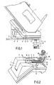
- the stand 1, shown in the Figures, for supporting an electric iron 2 while not in use, has a clamping device 3 for clamping the stand onto an ironing board 4.
- the stand is provided with a rotary tabel 5, and the clamping device 3 can be attached to the rotary table.
- the rotary table is rotatably supported in the bottom side of the stand.
- the axis of rotation 6 then extends perpendicularly to the bottom face (setting face) 7 of the base.
- the clamping device 3 is U-shaped, which is known per se, one of the legs 8 being connected to the rotary table by means of a pivotal construction.
- the pivotal shaft 9 of the pivotal construction is perpendicular to the axis of rotation 6 of the rotary table.
- the other leg 10 of the U-shaped clamping device is provided with a screw 11.
- the bottom side of the stand is provided with four recesses 12, which are located opposite the rotary tabel 5, forming a sort of cross.
- the width of each recess 12 is such that the leg 8 of the clamping device just fits therein.
- the clamping device can be locked relative to the stand. Because of the pivotal connection between the clamping device and the rotary table, the clamping device can be swiveled from a recess, thereafter positioned by means of the rotary table opposite a different recess, whereafter the clamping device can be locked again relative to the stand by moving the leg 8 into this recess.
- An alternative construction for locking the clamping device relative to the stand is a spring-loaded boss-identation mechanism of the type shown in Fig. 3.
- An interior wall 13 of the aperture in the stand in which the rotary table is accommodated is provided with a plurality of indentations 14 whereas the exterior wall 15 of the rotary table is provided with a resilient lug 16.
- a sort of boss 16a is provided at the end of the resilient lug, to cooperate with one of the indentations 14.
- the rotary table is fitted with a plurality of resilient lugs with bosses, so that a sort of snap structure for different positions between the rotary table/clamping device and the stand is obtained.
- the stand further has a storage space for the clamping device 3, so that when the stand is not in use, the clamping device does not form an obstacle when the stand is stored in, for example, a cupboard.
- One of the recesses 12 in which the clamping device 3 is locked relative to the stand coincides with the slotted recess for storing the clamping device.
- a spring-loaded boss-indentation mechanism 18 is arranged between the leg 8 of the clamping device and the rotary table.
- the storage position of the stand is shown in Fig. 4. So as to keep the storage space as small as possible, the leg 10 of the U-shaped clamping device 3, that is provided with the screw 11, is connected to the base 20 of the U by means of a hinge 19. Depending on how far the screw 11 is threaded into the leg 10, the leg including the screw must either be rotated or not rotated relative to the base 19. Different storage positions are shown in Fig. 1 by means of broken lines.
Applications Claiming Priority (2)
| Application Number | Priority Date | Filing Date | Title |
|---|---|---|---|
| NL8802545A NL8802545A (nl) | 1988-10-17 | 1988-10-17 | Voetstuk voor strijkijzer. |
| NL8802545 | 1988-10-17 |
Publications (1)
| Publication Number | Publication Date |
|---|---|
| EP0365078A1 true EP0365078A1 (de) | 1990-04-25 |
Family
ID=19853068
Family Applications (1)
| Application Number | Title | Priority Date | Filing Date |
|---|---|---|---|
| EP89202563A Withdrawn EP0365078A1 (de) | 1988-10-17 | 1989-10-11 | Ständer für elektrische Bügeleisen |
Country Status (7)
| Country | Link |
|---|---|
| US (1) | US5013003A (de) |
| EP (1) | EP0365078A1 (de) |
| JP (1) | JPH02149300A (de) |
| DE (1) | DE8912088U1 (de) |
| ES (1) | ES1011671Y (de) |
| FR (1) | FR2637918B3 (de) |
| NL (1) | NL8802545A (de) |
Cited By (3)
| Publication number | Priority date | Publication date | Assignee | Title |
|---|---|---|---|---|
| GB2235932A (en) * | 1989-09-16 | 1991-03-20 | Kenwood Marks Ltd | A base unit for supporting an iron |
| EP0881319A1 (de) * | 1997-05-27 | 1998-12-02 | Moulinex S.A. | Bügeleisenablage und Dampfbügelvorrichtung mit einer solchen Ablage |
| NL1014552C2 (nl) * | 2000-03-03 | 2001-09-04 | Okkerse B V | Strijkinrichting en strijkbout. |
Families Citing this family (5)
| Publication number | Priority date | Publication date | Assignee | Title |
|---|---|---|---|---|
| FR2679270A1 (fr) * | 1991-07-19 | 1993-01-22 | Philips Electronique Lab | Fer a repasser muni d'un detecteur de la nature des tissus. |
| US5414945A (en) * | 1994-05-10 | 1995-05-16 | Black & Decker, Inc. | Iron assembly including water cassette and base |
| US6375132B1 (en) | 2000-08-11 | 2002-04-23 | Elaine N. Tomlinson | Electric iron safety stand |
| BR112012010499A2 (pt) * | 2009-11-04 | 2016-03-15 | Panasonic Corp | ferro de passar sem fio |
| FR2974823B1 (fr) * | 2011-05-06 | 2013-05-17 | Seb Sa | Support pour fer a repasser |
Citations (11)
| Publication number | Priority date | Publication date | Assignee | Title |
|---|---|---|---|---|
| US1347123A (en) * | 1919-02-12 | 1920-07-20 | Aaron L Mann | Flatiron-holder |
| DE488197C (de) * | 1928-02-25 | 1929-12-21 | Franz Josef Loob | Absetzvorrichtung fuer elektrische Buegeleisen |
| US1903601A (en) * | 1932-05-02 | 1933-04-11 | Smolko Matthew | Iron stand |
| US2187059A (en) * | 1937-05-12 | 1940-01-16 | Schor | Clamp |
| US2382811A (en) * | 1943-11-06 | 1945-08-14 | Sargent & Co | Adjustable clamp for food choppers or the like |
| US2904296A (en) * | 1957-03-06 | 1959-09-15 | Bert A Graham | Fold away iron holder |
| US3082986A (en) * | 1961-02-07 | 1963-03-26 | Joseph C Campanizzi | Flat iron holder |
| FR2299786A7 (fr) * | 1975-02-01 | 1976-08-27 | Bosch Siemens Hausgeraete | Appareil menager, e |
| GB2088199A (en) * | 1980-11-28 | 1982-06-09 | Procter & Gamble | Dispenser suspension means emplying planar spring-loaded detent |
| EP0210538A2 (de) * | 1985-07-23 | 1987-02-04 | Braun Aktiengesellschaft | Vorrichtung zur Stromversorgung eines elektrischen Gerätes für den persönlichen Bedarf |
| DE8813186U1 (de) * | 1988-10-20 | 1988-12-15 | Bosch-Siemens Hausgeraete Gmbh, 8000 Muenchen, De |
Family Cites Families (8)
| Publication number | Priority date | Publication date | Assignee | Title |
|---|---|---|---|---|
| US1656320A (en) * | 1922-10-12 | 1928-01-17 | Rives L Crowder | Sadiron stand |
| US1737081A (en) * | 1928-04-21 | 1929-11-26 | Foucher Constance | Support for sadirons |
| US2523685A (en) * | 1946-04-27 | 1950-09-26 | Safety Household Appliance Cor | Press iron holder |
| US3202389A (en) * | 1963-12-09 | 1965-08-24 | Travco Plastics Co Inc | Combined flatiron support, electric outlet, and extension cord |
| US3295568A (en) * | 1964-09-17 | 1967-01-03 | Walt Inc De | Uni-directional indexing means for power-operated machine |
| US3367611A (en) * | 1965-12-29 | 1968-02-06 | Clark J R Co | Iron rest |
| US3926392A (en) * | 1974-06-28 | 1975-12-16 | Gen Electric | Iron minder |
| US4159816A (en) * | 1977-12-19 | 1979-07-03 | Toshiaki Miyamae | Collapsible universal fishing rod holding apparatus |
-
1988
- 1988-10-17 NL NL8802545A patent/NL8802545A/nl not_active Application Discontinuation
-
1989
- 1989-10-11 EP EP89202563A patent/EP0365078A1/de not_active Withdrawn
- 1989-10-11 DE DE8912088U patent/DE8912088U1/de not_active Expired - Lifetime
- 1989-10-13 ES ES19898903034U patent/ES1011671Y/es not_active Expired - Lifetime
- 1989-10-16 US US07/421,861 patent/US5013003A/en not_active Expired - Fee Related
- 1989-10-17 FR FR898913542A patent/FR2637918B3/fr not_active Expired - Lifetime
- 1989-10-17 JP JP1268294A patent/JPH02149300A/ja active Pending
Patent Citations (11)
| Publication number | Priority date | Publication date | Assignee | Title |
|---|---|---|---|---|
| US1347123A (en) * | 1919-02-12 | 1920-07-20 | Aaron L Mann | Flatiron-holder |
| DE488197C (de) * | 1928-02-25 | 1929-12-21 | Franz Josef Loob | Absetzvorrichtung fuer elektrische Buegeleisen |
| US1903601A (en) * | 1932-05-02 | 1933-04-11 | Smolko Matthew | Iron stand |
| US2187059A (en) * | 1937-05-12 | 1940-01-16 | Schor | Clamp |
| US2382811A (en) * | 1943-11-06 | 1945-08-14 | Sargent & Co | Adjustable clamp for food choppers or the like |
| US2904296A (en) * | 1957-03-06 | 1959-09-15 | Bert A Graham | Fold away iron holder |
| US3082986A (en) * | 1961-02-07 | 1963-03-26 | Joseph C Campanizzi | Flat iron holder |
| FR2299786A7 (fr) * | 1975-02-01 | 1976-08-27 | Bosch Siemens Hausgeraete | Appareil menager, e |
| GB2088199A (en) * | 1980-11-28 | 1982-06-09 | Procter & Gamble | Dispenser suspension means emplying planar spring-loaded detent |
| EP0210538A2 (de) * | 1985-07-23 | 1987-02-04 | Braun Aktiengesellschaft | Vorrichtung zur Stromversorgung eines elektrischen Gerätes für den persönlichen Bedarf |
| DE8813186U1 (de) * | 1988-10-20 | 1988-12-15 | Bosch-Siemens Hausgeraete Gmbh, 8000 Muenchen, De |
Cited By (6)
| Publication number | Priority date | Publication date | Assignee | Title |
|---|---|---|---|---|
| GB2235932A (en) * | 1989-09-16 | 1991-03-20 | Kenwood Marks Ltd | A base unit for supporting an iron |
| GB2235932B (en) * | 1989-09-16 | 1993-05-19 | Kenwood Marks Ltd | A base unit for supporting an iron |
| EP0881319A1 (de) * | 1997-05-27 | 1998-12-02 | Moulinex S.A. | Bügeleisenablage und Dampfbügelvorrichtung mit einer solchen Ablage |
| FR2763969A1 (fr) * | 1997-05-27 | 1998-12-04 | Moulinex Sa | Socle de repos pour fer a repasser et dispositif de repassage a vapeur comportant un tel socle |
| NL1014552C2 (nl) * | 2000-03-03 | 2001-09-04 | Okkerse B V | Strijkinrichting en strijkbout. |
| WO2001064992A1 (en) * | 2000-03-03 | 2001-09-07 | Okkerse B.V. | Ironing device and iron |
Also Published As
| Publication number | Publication date |
|---|---|
| DE8912088U1 (de) | 1989-11-30 |
| NL8802545A (nl) | 1990-05-16 |
| JPH02149300A (ja) | 1990-06-07 |
| ES1011671U (es) | 1990-05-01 |
| FR2637918B3 (fr) | 1990-10-05 |
| ES1011671Y (es) | 1990-12-01 |
| FR2637918A3 (fr) | 1990-04-20 |
| US5013003A (en) | 1991-05-07 |
Similar Documents
| Publication | Publication Date | Title |
|---|---|---|
| US4369487A (en) | Utility lamp | |
| EP0442428B1 (de) | Kameragriff | |
| US6254044B1 (en) | Tabletop tripod | |
| US4480556A (en) | Adjustable folding ironing board | |
| US2752116A (en) | Camera supporting heads for tripods or the like | |
| US4751540A (en) | Camera tripod | |
| US4439032A (en) | Portable camera support | |
| US5390885A (en) | Locking mechanism for a portable tripod of a Q-pad | |
| EP0365078A1 (de) | Ständer für elektrische Bügeleisen | |
| WO1999020935A1 (en) | Positionable flashlight and holder | |
| CN108266626B (zh) | 一种自拍装置 | |
| US4079908A (en) | Camera support apparatus | |
| US4988150A (en) | Keyboard stand | |
| US4832303A (en) | Reading material support stand | |
| US5172880A (en) | Holder for a blow dryer or other appliance | |
| US3228360A (en) | Detachable table top | |
| JPH0124996Y2 (de) | ||
| US5709044A (en) | Ironing board mounting bracket | |
| JP2002300069A (ja) | 無線通信カード用収納ケース | |
| KR920002133Y1 (ko) | 테이블용 절첩식다리 | |
| JPH0711639Y2 (ja) | 机 | |
| JP3146176B2 (ja) | バーベキューコンロ | |
| JPS6140268Y2 (de) | ||
| JPS60114Y2 (ja) | ミキサ−用スタンド | |
| JPS5918459Y2 (ja) | 譜面台の支持装置 |
Legal Events
| Date | Code | Title | Description |
|---|---|---|---|
| PUAI | Public reference made under article 153(3) epc to a published international application that has entered the european phase |
Free format text: ORIGINAL CODE: 0009012 |
|
| AK | Designated contracting states |
Kind code of ref document: A1 Designated state(s): DE ES FR GB IT |
|
| STAA | Information on the status of an ep patent application or granted ep patent |
Free format text: STATUS: THE APPLICATION IS DEEMED TO BE WITHDRAWN |
|
| 18D | Application deemed to be withdrawn |
Effective date: 19901026 |