EP0364270A1 - Übersetzungssteuerung für ein kontinuierlich variables Getriebe - Google Patents
Übersetzungssteuerung für ein kontinuierlich variables Getriebe Download PDFInfo
- Publication number
- EP0364270A1 EP0364270A1 EP89310476A EP89310476A EP0364270A1 EP 0364270 A1 EP0364270 A1 EP 0364270A1 EP 89310476 A EP89310476 A EP 89310476A EP 89310476 A EP89310476 A EP 89310476A EP 0364270 A1 EP0364270 A1 EP 0364270A1
- Authority
- EP
- European Patent Office
- Prior art keywords
- transmission ratio
- signal
- speed
- opening degree
- speed signal
- Prior art date
- Legal status (The legal status is an assumption and is not a legal conclusion. Google has not performed a legal analysis and makes no representation as to the accuracy of the status listed.)
- Granted
Links
Images


Classifications
-
- F—MECHANICAL ENGINEERING; LIGHTING; HEATING; WEAPONS; BLASTING
- F16—ENGINEERING ELEMENTS AND UNITS; GENERAL MEASURES FOR PRODUCING AND MAINTAINING EFFECTIVE FUNCTIONING OF MACHINES OR INSTALLATIONS; THERMAL INSULATION IN GENERAL
- F16H—GEARING
- F16H61/00—Control functions within control units of change-speed- or reversing-gearings for conveying rotary motion ; Control of exclusively fluid gearing, friction gearing, gearings with endless flexible members or other particular types of gearing
- F16H61/66—Control functions within control units of change-speed- or reversing-gearings for conveying rotary motion ; Control of exclusively fluid gearing, friction gearing, gearings with endless flexible members or other particular types of gearing specially adapted for continuously variable gearings
- F16H61/662—Control functions within control units of change-speed- or reversing-gearings for conveying rotary motion ; Control of exclusively fluid gearing, friction gearing, gearings with endless flexible members or other particular types of gearing specially adapted for continuously variable gearings with endless flexible members
- F16H61/66254—Control functions within control units of change-speed- or reversing-gearings for conveying rotary motion ; Control of exclusively fluid gearing, friction gearing, gearings with endless flexible members or other particular types of gearing specially adapted for continuously variable gearings with endless flexible members controlling of shifting being influenced by a signal derived from the engine and the main coupling
- F16H61/66259—Control functions within control units of change-speed- or reversing-gearings for conveying rotary motion ; Control of exclusively fluid gearing, friction gearing, gearings with endless flexible members or other particular types of gearing specially adapted for continuously variable gearings with endless flexible members controlling of shifting being influenced by a signal derived from the engine and the main coupling using electrical or electronical sensing or control means
Definitions
- the present invention relates to a control system for a continuously variable belt-drive automatic transmission (CVT) for a motor vehicle, and more particularly to a system for controlling the transmission ratio changing speed in accordance with the transmission ratio and the engine speed.
- CVT continuously variable belt-drive automatic transmission
- a transmission ratio changing speed control system in which changing speed of the transmission ratio is controlled in accordance with the difference between actual transmission ratio and a desired transmission ratio.
- the desired transmission ratio is corrected to obtain an optimum value in any driving condition, thereby improving feeling of acceleration.
- the desired transmission ratio (id) is quickly increased in accordance with a depression of an accelerator pedal of the vehicle. Thereafter, as the vehicle speed increases, the desired transmission ratio (id) gradually reduces.
- the transmission ratio changing speed is determined to control the actual transmission ratio (i) so as to converge toward the desired transmission ratio (id).
- acceleration G of the vehicle occurs as shown in Fig. 5c, which remarkably affects feeling of acceleration. That is, at acceleration, a driver feels a maximum acceleration Gm, a time t to reach the maximum acceleration Gm from a starting time of the acceleration, and the difference between the feeling of acceleration and the driver's requirement.
- drive pulley speed Np and driven pulley speed Ns (vehicle speed) of the CVT become high even if the actual transmission ratio i is the same as that at low speed driving. Accordingly, an increment ⁇ Np of the drive pulley speed becomes large with respect to the same transmission ratio changing speed di/dt as the low speed driving. If the transmission ratio is quickly increased to a large value, engine speed quickly increases, which gives unpleasant feeling like engine racing to the driver. Accordingly, it is preferable to keep the increment ⁇ Np of the drive pulley speed Np constant regardless to the magnitude of the acceleration and the vehicle speed.
- Japanese Patent Application Laid-open 59-208253 discloses a system for controlling the transmission ratio at kickdown.
- the transmission ratio changing speed changes gently at an early stage of acceleration in low speed driving or at low load of the engine, and increases quickly after a predetermined time.
- the transmission ratio changing speed is reduced at the early period of acceleration, the transmission does not produce sufficient driving torque. Therefore, the system does not meet requirement for rapid acceleration as obtained at kickdown.
- the object of the present invention is to provide a control system which improves acceleration characteristic in a wide range of vehicle speed.
- a control system for a continuously variable transmission for transmitting the power of an engine mounted on a motor vehicle, the engine having a throttle valve, the transmission comprising a drive pulley having a hydraulically shiftable disc and a hydraulic cylinder for operating the disc, a driven pulley having a hydraulically shiftable disc and a hydraulic cylinder for operating the disc, a belt engaged with both pulleys, the control system comprising a a first hydraulic circuit having a pump for supplying oil to both the hydraulic cylinders, a transmission ratio control valve for controlling the oil supplied to the cylinder of the drive pulley to change the transmission ratio to a desired transmission ratio.
- the system comprises transmission ratio control means for operating the transmission ratio control valve, a drive pulley speed sensor for producing a drive pulley speed signal, a driven pulley speed sensor for producing a driven pulley speed signal, a throttle position sensor for sensing opening degree of the throttle valve and for producing a throttle opening degree signal, first calculator means responsive to the drive pulley speed signal and the driven pulley speed signal for producing an actual transmission ratio signal, means responsive to the throttle opening degree signal and to the actual transmission ratio signal for producing a desired transmission ratio signal, downshift means responsive to a throttle opening degree signal representing a quick open of the throttle valve for increasing the value of the desired transmission ratio signal, second calculator means responsive to the desired transmission ratio signal and to the actual transmission ratio signal for producing a transmission ratio changing speed signal, third calculator means responsive to the throttle opening degree signal for producing a throttle opening degree changing speed signal, coefficient setting means responsive to the driven pulley speed signal as a vehicle speed signal and to the throttle opening degree signal for producing a correcting coefficient, correcting means for correcting the transmission ratio changing speed signal with
- the correcting coefficient is an increasing function of the throttle opening degree changing speed signal and a decreasing function of the driven pulley speed signal in a low vehicle speed range.
- a crankshaft 10 of an engine 1 is operatively connected to an electromagnetic powder clutch 2 for transmitting the power of the engine 1 to a continuously variable belt-drive automatic transmission 4 through a selector mechanism 3.
- the output of the belt-drive transmission 4 is transmitted to axles 8 of vehicle driving wheels 9 through an output shaft 13, a pair of intermediate reduction gears 5, an intermediate shaft 6, and a differential 7.
- the electromagnetic powder clutch 2 comprises an annular drive member 2a connected to crankshaft 10 of the engine 1, a driven member 2b secured to an input shaft 11 of the transmission 4, and a magnetizing coil 2c provided in the driven member 2b. Powder of magnetic material is provided in a gap between the drive member 2a and driven member 2b. When the magnetizing coil 2c is excited by the clutch current, driven member 2b is magnetized to produce a magnetic flux passing through the drive member 2a. The magnetic powder is aggregated in the gap by the magnetic flux and the driven member 2b is engaged with the drive member 2a by the powder. On the other hand, when the clutch current is cut off, the drive and driven members 2a and 2b are disengaged from one another.
- the selector mechanism 3 is provided between the input shaft 11 and a main shaft 12.
- the selector mechanism 3 is provided with a synchromesh mechanism comprising gears, hub, and sleeve for connecting the input shaft 11 and the main shaft 12 to selectively provide a driving position (D) and a reverse driving position (R).
- the continuously variable belt-drive automatic transmission 4 has the main shaft 12 and the output shaft 13 provided in parallel with the main shaft 12.
- a drive pulley 14 provided with a hydraulic cylinder 14a is mounted on the main shaft 12.
- a driven pulley 15 provided with a hydraulic cylinder 15a is mounted on the output shaft 13.
- a drive belt 16 engages with the drive pulley 14 and the driven pulley 15.
- Hydraulic cylinders 14a and 15a are communicated with an oil hydraulic control circuit HC.
- the cylinder 14a is supplied with pressurized oil by an oil pump P from an oil reservoir 17 passing through a line pressure control valve LC and a transmission ratio control valve TR.
- the cylinder 15a is applied with pressurized oil from the pump P.
- the hydraulic control circuit is responsive to vehicle speed, engine speed and throttle valve position for controlling the amount of oil supplied to the cylinders 14a and 15a.
- the pulleys 14 and 15 are operated by compressive forces of cylinders so that the running diameter of belt 16 varies to infinitely change the transmission ratio.
- An electronic control system for the clutch 2 and the belt-drive transmission 4 has an engine speed sensor 19, and rotating speed sensors 21 and 22 for respectively sensing rotating speeds of drive pulley 14 and the driven pulley 15.
- a choke switch 24 produces an output signal when a choke valve of the engine 1 is closed, and an air conditioner switch 23 produces an output signal at the operation of an air conditioner.
- a selector lever 25 connected to the selector mechanism 3 is provided with a select position sensor 26 for sensing the driving positions (D), (Ds), the neutral position (N) and the reverse position (R).
- An accelerator pedal switch 28 is provided for sensing the depression of an accelerator pedal 27, and a throttle position sensor 29 is provided.
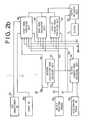
- Output signals of the sensors and pulses of the switches are applied to an electronic control unit 20 which produces a clutch current control signal to the clutch 2 and a control signal for controlling the transmission ratio (i) and a line pressure control signal to the control circuit 17.
- a reverse excitation mode deciding section 32 is applied with engine speed signal Ne of the sensor 19 and drive position signal of the select position sensor 26.
- the reverse excitation mode deciding section 32 produces a reverse excitation signal which is applied to an output deciding section 33, so that a small reverse current flows in the clutch 2 to release the clutch completely.
- a clutch current mode deciding section 34 is applied with signals from the reverse excitation mode deciding section 32 and accelerator pedal switch 28, and vehicle speed signal V from driven pulley speed sensor 22 for deciding driving conditions such as starting mode to produce output signals.
- the output signals are applied to a start mode providing section 35, drag mode providing section 36, and clutch lock-up engage mode providing section 37.
- the start mode providing section 35 decides clutch current of starting characteristic dependent on the engine speed Ne at ordinary start or at closing of the choke switch 24 or air conditioner switch 23.
- the starting characteristic is corrected by signals from the throttle valve opening degree ⁇ , vehicle speed V, and driving positions (D), (Ds) and reverse position (R).
- the drag mode providing section 36 decides a small drag current when the accelerator pedal 27 is released at a low speed in the driving position and the reverse position for providing a drag torque to the clutch 2 for the reduction of clearances formed in the transmission and for the smooth start of the vehicle.
- the clutch lock-up engage mode providing section 37 decides a lock-up current in response to the vehicle speed V and throttle opening degree ⁇ at the driving position and reverse position for entirely engaging the clutch 2. Outputs of sections 35, 36 and 37 are applied to the output deciding section 33 to control the clutch current.
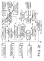
- the actual transmission ratio i and output signal ⁇ of the throttle position sensor 29 are fed to a desired drive pulley speed table 41 to derive a desired drive pulley speed Npd in accordance with values of the ratio i and signal ⁇ .
- the desired drive pulley speed Npd and the driven pulley speed Ns are fed to a desired transmission ratio calculator 42 to calculate a desired transmission ratio id in accordance with the desired drive pulley speed Npd and driven pulley speed Ns which corresponds to vehicle speed.
- the desired transmission ratio id is fed to a desired transmission ratio changing speed calculator 43 which produces a desired transmission ratio changing speed did/dt.
- the speed did/dt is the amount of change of the desired transmission ratio id during a predetermined time interval.
- Coefficient setting sections 44 and 60 are provided for producing coefficients K1 and K2 respectively.
- the term of (id - i) is a control quantity dependent on the difference between the desired and actual transmission ratios and did/dt is a term for compensating a phase lag in the system.
- the duty ratio D is supplied to a solenoid operated on-off valve 48 provided in the hydraulic circuit 17 through a driver 47.
- engine speed Ne from the engine speed sensor 19 and throttle opening degree ⁇ from the throttle position sensor 29 are applied to an engine torque table 50 to derive an engine torque T.
- the engine torque T and the actual transmission ratio i from the calculator 40 is applied to a desired line pressure table 51 to derive a desired line pressure P Ld .
- the desired line pressure P Ld and the maximum line pressure P Lmax are applied to a reduced line pressure calculator 53 wherein a reduced line pressure P LR is calculated based on the proportion of the desired line pressure P Ld to the maximum line pressure P Lmax .
- the reduced line pressure P LR is applied to a duty ratio table 54 to derive a duty ratio D L corresponding to the reduced line pressure P LR .
- the duty ratio D L is supplied to driver 55 which operates a solenoid operated on-off valve 56 provided in the hydraulic circuit 17 at the duty ratio.
- the transmission ratio changing speed di/dt is mainly determined by the control quantity (id-i) and the coefficient K1 in the above described equation.
- the control quantity (id-i) is determined in accordance with the desired transmission ratio id and the actual transmission ratio i at acceleration. Therefore, in order to correct the transmission ratio changing speed di/dt in low speed driving for improving the feeling of acceleration characteristic, the value of coefficient K1 must be properly set. Thus, the coefficient K1 is regarded as a correcting coefficient at acceleration.
- the acceleration can be expressed by changing speed ⁇ of throttle valve opening degree ⁇ . If the throttle opening changing speed ⁇ is high, it is regarded that large acceleration is required, and the correcting coefficient K1 is therefore set to a large value. Further, acceleration requirement becomes strong with vehicle speed reduces. Thus, the correcting coefficient K1 is set to a large value in low speed driving.
- the control system is provided with a throttle opening degree changing speed calculator 61 to which the throttle opening degree ⁇ from the throttle position sensor 29 is applied for calculating a throttle opening degree changing speed ⁇ .
- the throttle opening changing speed ⁇ and the driven pulley speed Ns as vehicle speed are applied to a coefficient setting section 60.
- the section 60 derives the coefficient K1 from the look-up table shown in Fig. 3. As shown in Fig. 3, the coefficient K1 is an increasing function of the throttle opening degree changing speed ⁇ and a decreasing function of the vehicle speed.
- cylinder 15a of the driven pulley 15 is supplied with the line pressure, and the cylinder 14a of the drive pulley 14 is drained.
- the drive belt 16 engages with the driven pulley 15 at a maximum running diameter to provide the largest transmission ratio (low speed stage).
- the clutch current increases progressively with increase of engine speed.
- the electromagnetic clutch 2 is gradually engaged, transmitting the engine power to the drive pulley 14.
- the power of the engine is transmitted to the output shaft 13 at the largest transmission ratio by the drive belt 16 and driven pulley 15, and further transmitted to axles of the driving wheels 9.
- the vehicle is started.
- the line pressure is applied to the cylinder 15a of the driven pulley 15.
- the cylinder 14a of the drive pulley 14 is drained.
- the actual transmission ratio calculator 40 produces an actual transmission ratio i.
- the desired drive pulley speed Npd is derived from the desired drive pulley speed table 41 in accordance with values of the ratio i and signal ⁇ .
- the desired transmission ratio calculator 42 calculates a desired transmission ratio id in accordance with the speeds Npd and the driven pulley speed Ns which corresponds to vehicle speed V.
- the actual transmission ratio i, desired transmission ratio id, desired transmission ratio chaging speed did/dt calculated at the transmission ratio changing speed calculator 43 and coefficients K1 and K2 are applied to the transmission ratio changing speed calculator 45 to produce a transmission ratio changing speed di/dt.
- the duty ratio D is supplied to a solenoid operated on-off valve 48 to produce a control pressure in the form of a pulse train for shifting a spool of the transmission ratio control valve between oil supply and drain positions.
- the off period of the solenoid operated on-off valve 48 becomes long, so that a spool of the transmission ratio control valve is positioned in the drain position for a longer time for draining the cylinder 14a.
- the transmission is downshifted.
- the transmission ratio control valve stays at the oil supply position for a longer time, so that oil is supplied to the cylinder 14a to upshift the transmission.
- the desired transmission ratio id is set to a low change speed value (large transmission ratio) as shown in Figs. 4a to 4c.
- the actual transmission ratio i is increased in response to the desired transmission ratio id.
- the throttle opening degree changing speed ⁇ is calculated at the calculator 61 and the correcting coefficient K1 is determined in response to the throttle opening degree changing speed ⁇ and the vehicle speed V at the section 60.
- the correcting coefficient K1 is set to a large value, so that the transmission ratio changing speed di/dt becomes large as shown in Fig. 4a.
- the acceleration G once becomes negative at downshifting, thereafter the acceleration G rapidly increases to provide the maximum acceleration Gm so as to meet the acceleration requirement of the driver.
- the coefficient K1 reduces, thereby reducing the transmission changing speed di/dt.
- the acceleration G varies as shown in Fig. 4b.
- a system of the second embodiment is provided with a correcting coefficient look-up table for improving the feeling of acceleration in high speed driving.
- the corresponding coefficient K1 is set to a smaller value in high speed driving than the low speed driving since the driver does not require rapid acceleration. If the throttle opening degree changing speed ⁇ becomes large and the vehicle speed becomes comparatively high, the correcting coefficient K1 becomes smaller.
- Fig. 6 shows a look-up table for the correcting coefficient K1 for correcting the transmission ratio changing speed di/dt at acceleration at high speed driving.
- the coefficient K1 is decreasing functions of the throttle opening degree changing speed ⁇ and the vehicle speed.
- the correcting coefficient K1 is determined comparatively to a large value as shown in Fig. 6.
- the transmission ratio changing speed di/dt becomes large comparatively, and the actual transmission ratio i corresponds to the desired transmission ratio id as shown by a dotted line of Fig. 7.
- the correcting coefficient K1 is sufficiently set to a small value to reduce the transmission ratio changing speed di/dt.
- the actual transmission ratio i slowly converges toward the desired transmission ratio id to prevent quick increase of the engine speed so that the feeling of acceleration is improved in the high speed driving.
- the transmission ratio changing speed is corrected in accordance with the driver's requirement for acceleration.
- Fig. 8 shows a look-up table for the correcting coefficient K1 in all speed driving showing the characteristic of the Fig. 3 and Fig. 6 together.
- the transmission ratio changing speed is corrected in accordance with the increasing function of the throttle opening degree changing speed and the decreasing function of the vehicle speed.
- the transmission ratio changing speed is corrected with the decreasing functions of the throttle opening degree changing speed and the vehicle speed.
- the acceleration characteristic is improved in a wide vehicle speed range.
Landscapes
- Engineering & Computer Science (AREA)
- General Engineering & Computer Science (AREA)
- Mechanical Engineering (AREA)
- Control Of Transmission Device (AREA)
- Control Of Driving Devices And Active Controlling Of Vehicle (AREA)
Applications Claiming Priority (4)
| Application Number | Priority Date | Filing Date | Title |
|---|---|---|---|
| JP26018488A JPH02107865A (ja) | 1988-10-14 | 1988-10-14 | 無段変速機の変速制御装置 |
| JP260184/88 | 1988-10-14 | ||
| JP26018388A JP2665955B2 (ja) | 1988-10-14 | 1988-10-14 | 無段変速機の変速制御装置 |
| JP260183/88 | 1988-10-14 |
Publications (2)
| Publication Number | Publication Date |
|---|---|
| EP0364270A1 true EP0364270A1 (de) | 1990-04-18 |
| EP0364270B1 EP0364270B1 (de) | 1993-12-15 |
Family
ID=26544480
Family Applications (1)
| Application Number | Title | Priority Date | Filing Date |
|---|---|---|---|
| EP89310476A Expired - Lifetime EP0364270B1 (de) | 1988-10-14 | 1989-10-12 | Übersetzungssteuerung für ein kontinuierlich variables Getriebe |
Country Status (3)
| Country | Link |
|---|---|
| US (1) | US5009129A (de) |
| EP (1) | EP0364270B1 (de) |
| DE (1) | DE68911466T2 (de) |
Cited By (4)
| Publication number | Priority date | Publication date | Assignee | Title |
|---|---|---|---|---|
| WO1997005407A1 (de) * | 1995-07-27 | 1997-02-13 | Zf Friedrichshafen Ag | Vorrichtung zur regelung des übersetzungsverhältnisses eines stufenlosen getriebes |
| FR2746476A1 (fr) * | 1996-03-22 | 1997-09-26 | Bosch Gmbh Robert | Systeme de reglage automatique du rapport de vitesses |
| WO1998005886A1 (de) * | 1996-08-01 | 1998-02-12 | Zf Friedrichshafen Ag | Verfahren zur vorgabe der übersetzung eines stufenlosen getriebes |
| GB2322917A (en) * | 1997-03-07 | 1998-09-09 | Nissan Motor | Shift control apparatus for continuously-variable transmission |
Families Citing this family (16)
| Publication number | Priority date | Publication date | Assignee | Title |
|---|---|---|---|---|
| JPH01132431A (ja) * | 1987-11-16 | 1989-05-24 | Honda Motor Co Ltd | 車両用無段変速機の変速制御方法 |
| JPH03204440A (ja) * | 1989-12-29 | 1991-09-06 | Aisin Aw Co Ltd | 無段変速機の制御装置 |
| JP2900194B2 (ja) * | 1991-01-22 | 1999-06-02 | 富士重工業株式会社 | 車両用無段変速機の圧力制御装置 |
| JP2906692B2 (ja) * | 1991-02-01 | 1999-06-21 | 日産自動車株式会社 | 無段変速機の変速制御装置 |
| JP3459290B2 (ja) * | 1994-02-28 | 2003-10-20 | 株式会社日立ユニシアオートモティブ | 無段変速機付き車両の制御装置 |
| DE4430447C2 (de) * | 1994-08-27 | 1997-10-16 | Deere & Co | Verfahren und Steuereinrichtung zur Steuerung des Antriebsstrangs eines Arbeitsfahrzeuges |
| JP3087001B2 (ja) * | 1994-09-05 | 2000-09-11 | 株式会社ユニシアジェックス | 無段変速機の制御装置 |
| DE4441876C1 (de) * | 1994-11-24 | 1996-01-04 | Porsche Ag | Verfahren zur Bestimmung der Schaltzeit für einen Übersetzungswechsel in einem stufenlosen Getriebe |
| US5788599A (en) * | 1995-04-12 | 1998-08-04 | Nissan Motor Co., Ltd. | Continuously variable transmission system for vehicle |
| DE19602033C2 (de) * | 1996-01-20 | 2000-06-21 | Telefunken Microelectron | Verfahren zur Regelung stufenlos verstellbarer Getriebe von Kraftfahrzeugen |
| DE19622108A1 (de) * | 1996-06-01 | 1997-12-04 | Zahnradfabrik Friedrichshafen | Verfahren zur Steuerung eines CVT |
| JP3425841B2 (ja) * | 1996-08-05 | 2003-07-14 | 株式会社日立ユニシアオートモティブ | 無段変速機の制御装置 |
| US6157884A (en) * | 1998-09-25 | 2000-12-05 | Nissan Motor Co., Ltd. | Speed ratio control device and control method for automatic transmission |
| JP4378844B2 (ja) * | 2000-05-23 | 2009-12-09 | トヨタ自動車株式会社 | 車両駆動装置 |
| JP5113715B2 (ja) * | 2008-10-20 | 2013-01-09 | アイシン・エィ・ダブリュ株式会社 | 動力伝達装置およびこれを搭載する車両 |
| US8954245B2 (en) * | 2012-01-13 | 2015-02-10 | Caterpillar Inc. | Method of controlling gear ratio rate of change in continuously variable transmission |
Citations (3)
| Publication number | Priority date | Publication date | Assignee | Title |
|---|---|---|---|---|
| JPS59208253A (ja) * | 1983-05-09 | 1984-11-26 | Toyota Motor Corp | 車両用無段変速機の制御方法 |
| EP0207227A1 (de) * | 1985-06-29 | 1987-01-07 | Fuji Jukogyo Kabushiki Kaisha | Steuersystem für stufenlose Getriebe |
| EP0228897A2 (de) * | 1985-12-25 | 1987-07-15 | Fuji Jukogyo Kabushiki Kaisha | Übersetzungsverhältnis-Steuersystem für ein stufenlos regelbares Getriebe |
Family Cites Families (8)
| Publication number | Priority date | Publication date | Assignee | Title |
|---|---|---|---|---|
| JPS624643A (ja) * | 1985-06-29 | 1987-01-10 | Fuji Heavy Ind Ltd | 無段変速機の制御装置 |
| US4782934A (en) * | 1986-01-07 | 1988-11-08 | Fuji Jukogyo Kabushiki Kaisha | Control system for a continuously variable transmission |
| JPS62227825A (ja) * | 1986-03-28 | 1987-10-06 | Fuji Heavy Ind Ltd | 無段変速機の制御装置 |
| JPS6353128A (ja) * | 1986-08-20 | 1988-03-07 | Fuji Heavy Ind Ltd | 無段変速機の変速比制御装置 |
| JPS6353129A (ja) * | 1986-08-20 | 1988-03-07 | Fuji Heavy Ind Ltd | 無段変速機の変速比制御装置 |
| JPS6353130A (ja) * | 1986-08-23 | 1988-03-07 | Fuji Heavy Ind Ltd | 無段変速機の制御装置 |
| JPH0694901B2 (ja) * | 1987-06-02 | 1994-11-24 | 富士重工業株式会社 | ロックアップトルコン付無段変速機の制御装置 |
| JP2541821B2 (ja) * | 1987-06-30 | 1996-10-09 | 富士重工業株式会社 | 無段変速機の変速制御装置 |
-
1989
- 1989-10-06 US US07/418,187 patent/US5009129A/en not_active Expired - Lifetime
- 1989-10-12 DE DE89310476T patent/DE68911466T2/de not_active Expired - Fee Related
- 1989-10-12 EP EP89310476A patent/EP0364270B1/de not_active Expired - Lifetime
Patent Citations (3)
| Publication number | Priority date | Publication date | Assignee | Title |
|---|---|---|---|---|
| JPS59208253A (ja) * | 1983-05-09 | 1984-11-26 | Toyota Motor Corp | 車両用無段変速機の制御方法 |
| EP0207227A1 (de) * | 1985-06-29 | 1987-01-07 | Fuji Jukogyo Kabushiki Kaisha | Steuersystem für stufenlose Getriebe |
| EP0228897A2 (de) * | 1985-12-25 | 1987-07-15 | Fuji Jukogyo Kabushiki Kaisha | Übersetzungsverhältnis-Steuersystem für ein stufenlos regelbares Getriebe |
Cited By (9)
| Publication number | Priority date | Publication date | Assignee | Title |
|---|---|---|---|---|
| WO1997005407A1 (de) * | 1995-07-27 | 1997-02-13 | Zf Friedrichshafen Ag | Vorrichtung zur regelung des übersetzungsverhältnisses eines stufenlosen getriebes |
| US5947862A (en) * | 1995-07-27 | 1999-09-07 | Zf Friedrichshafen Ag | Device for controlling the gear ratio of a continuously variable transmission |
| FR2746476A1 (fr) * | 1996-03-22 | 1997-09-26 | Bosch Gmbh Robert | Systeme de reglage automatique du rapport de vitesses |
| WO1998005886A1 (de) * | 1996-08-01 | 1998-02-12 | Zf Friedrichshafen Ag | Verfahren zur vorgabe der übersetzung eines stufenlosen getriebes |
| US6216075B1 (en) | 1996-08-01 | 2001-04-10 | Zf Friedrichshafen Ag | Process for determining the operating point of a continuously variable transmission |
| GB2322917A (en) * | 1997-03-07 | 1998-09-09 | Nissan Motor | Shift control apparatus for continuously-variable transmission |
| GB2322917B (en) * | 1997-03-07 | 1999-06-23 | Nissan Motor | Shift control apparatus for continuously variable transmission |
| US6019701A (en) * | 1997-03-07 | 2000-02-01 | Nissan Motor Co., Ltd. | Shift control apparatus for continuously variable transmission |
| US6244986B1 (en) | 1997-03-07 | 2001-06-12 | Nissan Motor Co., Ltd. | Shift control apparatus for continuously variable transmission |
Also Published As
| Publication number | Publication date |
|---|---|
| DE68911466D1 (de) | 1994-01-27 |
| EP0364270B1 (de) | 1993-12-15 |
| DE68911466T2 (de) | 1994-04-14 |
| US5009129A (en) | 1991-04-23 |
Similar Documents
| Publication | Publication Date | Title |
|---|---|---|
| EP0364270B1 (de) | Übersetzungssteuerung für ein kontinuierlich variables Getriebe | |
| EP0231059B1 (de) | Steuervorrichtung für ein stufenlos regelbares Getriebe | |
| US4730712A (en) | System for controlling a clutch for a motor vehicle | |
| US5009127A (en) | Transmission ratio control system for a continuously variable transmission | |
| US4947971A (en) | Control system for a clutch for a motor vehicle | |
| US4880094A (en) | Control system for a clutch for a vehicle | |
| US4850935A (en) | Transmission ratio control system for a continuously variable transmission | |
| US4923433A (en) | Transmission ratio control system for a continuously variable transmission | |
| US4823925A (en) | Control system for a clutch for a vehicle | |
| US4825991A (en) | Control system for a clutch for a vehicle | |
| US5209332A (en) | Control system for a clutch of a motor vehicle | |
| US5217086A (en) | Control system for a vehicle | |
| US4846321A (en) | Control system for a clutch for a vehicle | |
| US4977988A (en) | Control system for a clutch for a vehicle | |
| US4792027A (en) | Control system for a clutch for a vehicle | |
| EP0240281B1 (de) | Steuersystem für eine elektromagnetische Kraftfahrzeugkupplung | |
| US4830155A (en) | Control system for a clutch for a vehicle | |
| US4848544A (en) | Control system for a clutch for a vehicle | |
| JP2903155B2 (ja) | 無段変速機の変速制御装置 | |
| EP0304228A1 (de) | Regelungssystem für ein Kraftfahrzeug | |
| JP2876209B2 (ja) | 無段変速機の制御装置 | |
| JP2741032B2 (ja) | 無段変速機の変速制御装置 | |
| JP2599291B2 (ja) | 無段変速機の変速制御装置 | |
| JP2598253B2 (ja) | 車両用自動クラツチの制御装置 | |
| JPH02107865A (ja) | 無段変速機の変速制御装置 |
Legal Events
| Date | Code | Title | Description |
|---|---|---|---|
| PUAI | Public reference made under article 153(3) epc to a published international application that has entered the european phase |
Free format text: ORIGINAL CODE: 0009012 |
|
| 17P | Request for examination filed |
Effective date: 19891020 |
|
| AK | Designated contracting states |
Kind code of ref document: A1 Designated state(s): DE GB IT NL |
|
| 17Q | First examination report despatched |
Effective date: 19911203 |
|
| GRAA | (expected) grant |
Free format text: ORIGINAL CODE: 0009210 |
|
| AK | Designated contracting states |
Kind code of ref document: B1 Designated state(s): DE GB IT NL |
|
| PG25 | Lapsed in a contracting state [announced via postgrant information from national office to epo] |
Ref country code: IT Free format text: LAPSE BECAUSE OF FAILURE TO SUBMIT A TRANSLATION OF THE DESCRIPTION OR TO PAY THE FEE WITHIN THE PRE;WARNING: LAPSES OF ITALIAN PATENTS WITH EFFECTIVE DATE BEFORE 2007 MAY HAVE OCCURRED AT ANY TIME BEFORE 2007. THE CORRECT EFFECTIVE DATE MAY BE DIFFERENT FROM THE ONE RECORDED.SCRIBED TIME-LIMIT Effective date: 19931215 Ref country code: NL Effective date: 19931215 |
|
| REF | Corresponds to: |
Ref document number: 68911466 Country of ref document: DE Date of ref document: 19940127 |
|
| NLV1 | Nl: lapsed or annulled due to failure to fulfill the requirements of art. 29p and 29m of the patents act | ||
| PLBE | No opposition filed within time limit |
Free format text: ORIGINAL CODE: 0009261 |
|
| STAA | Information on the status of an ep patent application or granted ep patent |
Free format text: STATUS: NO OPPOSITION FILED WITHIN TIME LIMIT |
|
| 26N | No opposition filed | ||
| PGFP | Annual fee paid to national office [announced via postgrant information from national office to epo] |
Ref country code: GB Payment date: 19981016 Year of fee payment: 10 Ref country code: DE Payment date: 19981016 Year of fee payment: 10 |
|
| REG | Reference to a national code |
Ref country code: GB Ref legal event code: 746 Effective date: 19980924 |
|
| PG25 | Lapsed in a contracting state [announced via postgrant information from national office to epo] |
Ref country code: GB Free format text: LAPSE BECAUSE OF NON-PAYMENT OF DUE FEES Effective date: 19991012 |
|
| GBPC | Gb: european patent ceased through non-payment of renewal fee |
Effective date: 19991012 |
|
| PG25 | Lapsed in a contracting state [announced via postgrant information from national office to epo] |
Ref country code: DE Free format text: LAPSE BECAUSE OF NON-PAYMENT OF DUE FEES Effective date: 20000801 |