EP0362558A2 - Dispositif d'arrosage - Google Patents
Dispositif d'arrosage Download PDFInfo
- Publication number
- EP0362558A2 EP0362558A2 EP89116234A EP89116234A EP0362558A2 EP 0362558 A2 EP0362558 A2 EP 0362558A2 EP 89116234 A EP89116234 A EP 89116234A EP 89116234 A EP89116234 A EP 89116234A EP 0362558 A2 EP0362558 A2 EP 0362558A2
- Authority
- EP
- European Patent Office
- Prior art keywords
- spray nozzle
- housing
- spray
- main channel
- channel
- Prior art date
- Legal status (The legal status is an assumption and is not a legal conclusion. Google has not performed a legal analysis and makes no representation as to the accuracy of the status listed.)
- Granted
Links
Images


Classifications
-
- B—PERFORMING OPERATIONS; TRANSPORTING
- B05—SPRAYING OR ATOMISING IN GENERAL; APPLYING FLUENT MATERIALS TO SURFACES, IN GENERAL
- B05B—SPRAYING APPARATUS; ATOMISING APPARATUS; NOZZLES
- B05B3/00—Spraying or sprinkling apparatus with moving outlet elements or moving deflecting elements
- B05B3/02—Spraying or sprinkling apparatus with moving outlet elements or moving deflecting elements with rotating elements
- B05B3/04—Spraying or sprinkling apparatus with moving outlet elements or moving deflecting elements with rotating elements driven by the liquid or other fluent material discharged, e.g. the liquid actuating a motor before passing to the outlet
- B05B3/0409—Spraying or sprinkling apparatus with moving outlet elements or moving deflecting elements with rotating elements driven by the liquid or other fluent material discharged, e.g. the liquid actuating a motor before passing to the outlet with moving, e.g. rotating, outlet elements
- B05B3/0418—Spraying or sprinkling apparatus with moving outlet elements or moving deflecting elements with rotating elements driven by the liquid or other fluent material discharged, e.g. the liquid actuating a motor before passing to the outlet with moving, e.g. rotating, outlet elements comprising a liquid driven rotor, e.g. a turbine
- B05B3/0422—Spraying or sprinkling apparatus with moving outlet elements or moving deflecting elements with rotating elements driven by the liquid or other fluent material discharged, e.g. the liquid actuating a motor before passing to the outlet with moving, e.g. rotating, outlet elements comprising a liquid driven rotor, e.g. a turbine with rotating outlet elements
- B05B3/0431—Spraying or sprinkling apparatus with moving outlet elements or moving deflecting elements with rotating elements driven by the liquid or other fluent material discharged, e.g. the liquid actuating a motor before passing to the outlet with moving, e.g. rotating, outlet elements comprising a liquid driven rotor, e.g. a turbine with rotating outlet elements the rotative movement of the outlet elements being reversible
- B05B3/044—Tubular elements holding several outlets, e.g. apertured tubes, oscillating about an axis substantially parallel to the tubular element
-
- B—PERFORMING OPERATIONS; TRANSPORTING
- B05—SPRAYING OR ATOMISING IN GENERAL; APPLYING FLUENT MATERIALS TO SURFACES, IN GENERAL
- B05B—SPRAYING APPARATUS; ATOMISING APPARATUS; NOZZLES
- B05B1/00—Nozzles, spray heads or other outlets, with or without auxiliary devices such as valves, heating means
- B05B1/30—Nozzles, spray heads or other outlets, with or without auxiliary devices such as valves, heating means designed to control volume of flow, e.g. with adjustable passages
- B05B1/3026—Nozzles, spray heads or other outlets, with or without auxiliary devices such as valves, heating means designed to control volume of flow, e.g. with adjustable passages the controlling element being a gate valve, a sliding valve or a cock
Definitions
- the invention relates to a sprinkling device such as is used, for example, as a portable or stationary device for sprinkling on lawns, beds or the like.
- the irrigation device has spray nozzles which are provided, for example, in a row on at least one nozzle carrier.
- the nozzle holder which could be formed by a curved pipe section or the like, is preferably designed as a housing with different internal and / or external cross sections and has a water supply for supplying the water to the spray nozzles, so that targeted irrigation is ensured.
- the spray nozzle housing can form at least part of its length essentially over its entire inner cross section the associated section of the water supply in such a way that the housing is practically completely filled with water during operation and under pressure, and that this water flows directly from the housing into the spray nozzles occurs, which are formed by nozzle openings in a housing wall of the spray nozzle housing.
- This irrigation device has proven itself well in operation, especially since the spray nozzle housing is also suitable for accommodating a swivel drive, with which the water curtain emerging from the spray nozzles can be pivoted back and forth to irrigate a correspondingly large base area.
- the invention is further based on the object of avoiding disadvantages of known designs, in particular to provide a sprinkling device of the type mentioned, which makes it possible in a simple manner to restrict the water flow within relatively narrow limits to precisely defined areas with a compact design.
- a separate main channel is assigned to the spray nozzle housing for water flow between a line connection and the spray nozzles, the clear cross sections of which can be substantially or many times smaller than those of the housing and against which the rest of the spray nozzle housing is preferably sealed or sealable, so that the housing primarily forms the function of a support profile or support housing, for example for the main channel, the spray nozzles and the like.
- the weight of the irrigation device can also be kept very low in operation because of the small volume of its water supply, and moreover takes place very quickly or practically immediately when the irrigation device is started up, that is to say at the start of the water supply the pressure build-up at the spray nozzles, because the entire housing does not have to be filled with water and vented through the spray nozzles beforehand.
- Another advantage is that the relatively narrow main channel is much easier to seal against unwanted water leakage than a relatively large-volume housing, especially since the flow cross-section of the main channel is at least at its narrowest points in the order of magnitude of that of the connection for the water pipe or even smaller can.
- the main channel could protrude beyond the housing in the longitudinal direction of the housing with at least one end, be at least partially outside of the housing transversely to this longitudinal direction or be provided entirely on the outside of the housing and also be at least partially formed in one piece with the housing, but this results in a particular one advantageous embodiment if the main channel is formed on the one hand by a separate, self-assembling assembly and on the other hand is essentially completely within the spray nozzle housing. If the main channel has the spray nozzles e.g. in the sense that they belong to the assembly mentioned, the watertight seal is further simplified.
- the swivel drive which has, for example, a hydraulic motor with gear connected to the water guide, can be completely moved out of the water guide as a separate structural unit insofar as the motor only flows through a motor or drive housing in a defined way, but is not washed around by water on its outside, so that, for example, the transmission located within this separate drive housing does not run in the water but in a sealed transmission chamber.
- a water outlet connection of the An drive housing is expediently sealed via a connecting piece within the spray nozzle housing directly connected to the main channel.
- the invention is also based on the object of being able to influence the guidance of the water when leaving the spray nozzle housing in such a way that certain characteristics of the emerging water curtain, e.g. whose width, density or the like can be changed.
- one or more spray nozzles can be switched off individually or in groups at least partially, but preferably completely with regard to the water outlet, so that less or no water emerges from them during operation.
- the adjustable nozzles are provided at the front or rear end of the at least one row of spray nozzles, the width of the escaping water curtain can be effectively reduced by turning off one or more of these end nozzles to adapt to the size of the base area to be irrigated, especially if these End nozzles are inclined in a fan shape obliquely outwards so that the width of the water curtain can be selected to be substantially greater than the length of the row of nozzles.
- each spray nozzle can be closed with a separate valve which is essentially inside the spray nozzle housing and which is simple Slider valve can be actuated by a linear, approximately parallel to the emerging water supply and / or transversely or at right angles to the housing axis movement.
- shut-off devices for the spray nozzles can belong to the assembly of this main channel or their fixed parts can be formed in one piece with the main channel.
- a separate handle is expediently provided, the handles for adjacent spray nozzles in the longitudinal direction of the row of nozzles one behind the other and from the outside of the housing can be directly accessible, so that they practically form an indication of the setting state of the sprinkling device, because based on their position, the closed or open state of the associated spray nozzle can already be recognized from a distance.
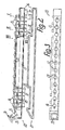
- the irrigation device 1 has a thin-walled, plastic and essentially two-part spray nozzle housing 2, the length of which is several times greater than its cross-sectional width and that between end supports 5, 6 of a stand 3 or in the area its ends is rotatably or pivotably mounted about an axis parallel to the standing plane and to its longitudinal central axis.
- the stand 3 has downwardly diverging stand brackets 4, which are attached at their ends to the supports 5, 6.
- a drive device 7 is provided essentially in this or between the supports 5, 6 with a water motor 8 which is inserted into a receptacle in the rear end of the housing and lying in the swivel axis .
- the drive device 7 is assigned a switchover device 9 for changing the swivel angle and the position of the swivel range with respect to a reference plane, the switchover device 9 being adjustable by hand with adjusting rings located between the rear end of the housing 2 and the associated carrier 5.
- the spray nozzle housing has a water guide 10 for the connection of a line connection 11 to spray nozzles 12, 13, 14, which is provided essentially along the top of the housing 2 at a distance above the pivot axis and the clear cross section both at heights direction as well as in the width direction is significantly smaller than the associated inner cross section of the housing 2.
- the line connection 11 is expediently provided in the pivot axis on the side of the associated carrier 5 facing away from the rear end of the housing in the form of a plug-in coupling socket, to which a water hose with a corresponding counter-coupling piece can be connected in an easily detachable manner.
- the spray nozzles 12, 13, 14 are provided in a single row parallel to the pivot axis one behind the other over most of the length of the housing 2 directed upwards at its top, such that they lie in an axial plane of the housing 2.
- the spray nozzles are oriented at different angles, in particular within this plane, the outermost nozzles located at the ends of the row of nozzles preferably being inclined to one another or with respect to a transverse median plane of the row of nozzles, diverging at the greatest angle of, for example, approximately 34 °, while this angle of inclination
- Spray nozzle to spray nozzle can decrease by approximately the same angular dimensions with increasing approach to the transverse center plane up to approximately 0 °.
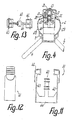
- the housing of the water motor 8, through which the entire quantity of water supplied through the line connection 11 flows, has at its front end a water outlet connection 17 protruding in the swivel axis, above which an approximately right-angled downward, also nozzle-shaped one Water inlet connection 18 of the channel box 16 is located.
- the two connections are connected to one another via an angled connecting elbow 19 which is sealed on the outer circumference of the water outlet connection 17 and likewise sealed in the water inlet connection 18 and can only be held by these plug connections.
- the channel box 16 is formed only by two components, namely a box body 20 open on a lateral long side and an approximately strip-shaped box lid 21 which engages in this long side to close the open long side of the box body 20 and for example sealed by ultrasonic welding.
- the box lid 21 extends essentially over the entire length of the box body.
- the channel box 16 has substantially square cross-sections in the areas delimiting the main channel 15, so that the box body 20 is approximately U-shaped in cross-section due to the design described in these areas and the box lid 21 serves to connect the U-legs .
- the upper, in the central region of the row of nozzles formed by the U-leg of the box body 20 is formed in one piece with mushroom-like projecting nozzle heads 23, each of which is penetrated by a nozzle channel 24 aligned in the manner described and thereby one of the spray nozzles 12, 13 , 14 forms.
- lateral side grooves 25 are provided laterally in the nozzle heads over the length of the row of nozzles, one side flank of which is formed by the top of the upper box wall 22 and the other side flank of which is formed by the undersides of the spherical ball-shaped head sections , so that these head sections over shaft-like redu adorned sections 26 pass into the channel box 16.
- the spray nozzle housing 2 consists of two essentially mirror-symmetrical, complementary housing shells 28, 29, which essentially join one another with their wall edges facing one another in the axial plane of the housing axis coinciding with the nozzle plane, and are connected to one another in the region of these wall edges by ultrasonic welding or the like .
- the two housing shells 27, 28 do not directly adjoin one another, but rather each on one side of the longitudinal web 27, engaging in the side grooves 25 so that the spherical-spherical sections of the nozzle heads 23 above the top wall 29 of the housing 2 protruding and this top wall overlapping safety buttons form with which the channel box 16 is suspended from the top wall 31 of the spray nozzle housing 2.
- the housing 2 is stepped approximately cylindrical over most of its length in its basic shape.
- the housing 2 In the rear area, which receives the drive device 7, the housing 2 forms a box-shaped area which projects downward beyond the cylindrical basic shape.
- the bottom walls of these longitudinal recesses merging into wall parts 32 projecting upward above the cylindrical basic shape, which form the approximately flat top wall 31, which is substantially narrower than the diameter of the cylindrical basic shape.
- the housing axis 30 lying in the pivot axis essentially coincides with the central axis of the cylindrical basic shape.
- the channel box 16 is provided with a cleaning opening 33 which is delimited by a connecting piece which engages in the top wall of the spray nozzle housing 2 and can be closed in a detachable manner with a cover 34 which is accessible from the outside.
- a nozzle needle 35 for cleaning the nozzle channels 24 can be provided on the inside of the cover 34.
- the three rearmost spray nozzles 13 and the three frontmost spray nozzles 14 of the row of nozzles can each be switched on and off independently of one another in the sense that they can be connected to the water guide 10 by hand or blocked off from it or throttled in terms of their inlet cross section.
- a check valve 36 in the form of a slide valve is provided for each of these spray nozzles 13 and 14, with all slide valves lying parallel to one another and preferably in the common axial plane of the spray nozzles directly adjacent to the inner ends of the associated nozzle channels 24.
- a pipe socket-shaped cylindrical valve channel 37 is provided within the channel box 16, which projects in one piece from the upper box wall 22 down to the underside of the main channel 15 and is open at this lower end 39 is.
- Each valve channel 37 penetrates the main channel 15 in the area of its associated longitudinal section with its jacket, in such a way that this valve channel 37 can be connected to the main channel 15 only by providing a side inlet 38 in its jacket as an opening.
- the main ka nal 15 is in the area of the shut-off valves 36 or in the area of the respective group of adjacent, adjustable spray nozzles 13 or 14 by a gradation of the upper box wall 22 downwards and by a laterally offset arrangement in cross section according to the figures relative to the common axial plane of the spray nozzles 5 and 9 are reduced, the main channel and the respective valve channel 37 being delimited and separated from one another in the associated area by a single common intermediate wall in which the side inlet 38 is provided.
- valve slide 40 is formed in one piece with a handle 42, with which it forms a slide part 41 which is essentially U-shaped in the longitudinal view of the housing 2 and has U-legs 43 pointing upwards.
- the web-shaped U-crosspiece 44 of this slide part 41 has the valve slide 40 which projects freely in the middle of its width and lies between the U-legs 43, while the approximately parallel plate-shaped U-legs 43 each have a molded-on individual handle at their upper ends Form 42 with the handle surfaces facing away from each other and the upper pressure surfaces.
- the individual handles 42 engage in recesses in the wall parts 32 which are adapted to them and on the inner sides of which the U-legs 43 are located, so that the slide part 41 is guided in a precisely defined manner thereby and by the valve slide 40.
- the upper sides of the handle 42 which is also guided in lateral recesses in the upper box wall 32, lie approximately flush with the upper side of the top wall 31 of the spray nozzle housing 2, at least one facing inwards over the inside of the associated U- Leg 43 projecting individual handle 42 can strike on the top of the profile section of the box body 20 forming the main channel 15.
- the handle 42 As shown in Fig. 1 for the last two spray nozzles 13, 14, is moved upward, so that it protrudes on both sides of the associated nozzle head over the top of the spray nozzle housing 2, but for her Engagement in the respective wall part 32 provided recess 45 remains essentially closed in that this recess 45 is completely covered on the inside by the associated U-leg 43.
- Corresponding continuations of these recesses 45 in the top wall 31 and in the upper box wall 32 remain closed in each position by the individual handles 42.
Landscapes
- Nozzles (AREA)
- Organic Low-Molecular-Weight Compounds And Preparation Thereof (AREA)
- Catching Or Destruction (AREA)
- Infusion, Injection, And Reservoir Apparatuses (AREA)
Applications Claiming Priority (2)
| Application Number | Priority Date | Filing Date | Title |
|---|---|---|---|
| DE3833983A DE3833983A1 (de) | 1988-10-06 | 1988-10-06 | Beregnungsvorrichtung |
| DE3833983 | 1988-10-06 |
Publications (3)
| Publication Number | Publication Date |
|---|---|
| EP0362558A2 true EP0362558A2 (fr) | 1990-04-11 |
| EP0362558A3 EP0362558A3 (en) | 1990-10-24 |
| EP0362558B1 EP0362558B1 (fr) | 1994-06-01 |
Family
ID=6364495
Family Applications (1)
| Application Number | Title | Priority Date | Filing Date |
|---|---|---|---|
| EP89116234A Expired - Lifetime EP0362558B1 (fr) | 1988-10-06 | 1989-09-02 | Dispositif d'arrosage |
Country Status (4)
| Country | Link |
|---|---|
| US (1) | US5052622A (fr) |
| EP (1) | EP0362558B1 (fr) |
| AT (1) | ATE106281T1 (fr) |
| DE (2) | DE3833983A1 (fr) |
Cited By (2)
| Publication number | Priority date | Publication date | Assignee | Title |
|---|---|---|---|---|
| EP0648544A1 (fr) * | 1993-10-14 | 1995-04-19 | Claber S.P.A. | Dispositif irrigateur avec bras oscillant |
| WO2010133236A1 (fr) * | 2009-05-19 | 2010-11-25 | Alfred Kärcher Gmbh & Co. Kg | Dispositif d'arrosage |
Families Citing this family (15)
| Publication number | Priority date | Publication date | Assignee | Title |
|---|---|---|---|---|
| US5305956A (en) * | 1992-08-03 | 1994-04-26 | Wang H | Oscillatory sprinkler |
| US5350115A (en) * | 1993-08-10 | 1994-09-27 | Vermont American Corporation | Lawn sprinkler with cam-controlled variable spray pattern |
| FR2712354B1 (fr) * | 1993-11-10 | 1996-01-05 | Tecnoma | Dispositif pour produire un courant d'air ayant une forme aplatie en section transversale. |
| US5526982A (en) * | 1993-12-23 | 1996-06-18 | The Toro Company | Adjustable sprinkler nozzle |
| US5511727A (en) * | 1994-06-01 | 1996-04-30 | L. R. Nelson Corporation | Wave sprinkler with improved adjustable spray assembly |
| US5645218A (en) * | 1994-06-01 | 1997-07-08 | L. R. Nelson Corporation | Unitized sprinkler assembly with adjustable water control mechanism |
| IT236573Y1 (it) * | 1995-01-03 | 2000-08-17 | Claber Spa | Fiancata motrice per irrigatore a braccio oscillante |
| US5628458A (en) * | 1995-04-12 | 1997-05-13 | Kuo; Yu-Neng | Spray tube assembly for oscillating sprinklers |
| US5657928A (en) * | 1995-11-06 | 1997-08-19 | Jian; May-Be | Adjustment structure of a rotary sprinkler |
| DE19830860A1 (de) * | 1998-07-10 | 2000-01-13 | Gardena Kress & Kastner Gmbh | Verfahren zur Verstellung des Regnerbildes einer Beregnungsvorrichtung und Beregnungsvorrichtung |
| CA2266247A1 (fr) * | 1999-03-22 | 2000-09-22 | Alexander Harcus Coote | Disposition amelioree des trous du tube d'aspersion des arroseurs oscillants de pelouse classiques |
| US20060261184A1 (en) * | 2005-05-23 | 2006-11-23 | Tropical Ventures, Llc | Device for discharging a stream of fluid in a pattern and method of using same |
| US8087968B2 (en) | 2005-05-23 | 2012-01-03 | Thought Development, Inc. | Device for discharging a stream of fluid in a pattern and method of using same |
| TWI273884B (en) * | 2006-03-24 | 2007-02-21 | Yuan Mei Corp | Improved structure of water-stopping and -discharging controller of sprinkler |
| TWI273885B (en) * | 2006-03-24 | 2007-02-21 | Yuan Mei Corp | Improved structure of water-stopping and -discharging controller of sprinkler |
Citations (3)
| Publication number | Priority date | Publication date | Assignee | Title |
|---|---|---|---|---|
| US2673122A (en) * | 1951-04-19 | 1954-03-23 | William C Wehner | Lawn sprinkler |
| US3332624A (en) * | 1965-01-28 | 1967-07-25 | First Res Corp | Turret lawn sprinkler with oscillating mechanism |
| FR2201028A1 (fr) * | 1972-09-30 | 1974-04-26 | Kupex Ag |
Family Cites Families (13)
| Publication number | Priority date | Publication date | Assignee | Title |
|---|---|---|---|---|
| DE7115718U (de) * | 1971-08-19 | Perrot Regnerbau Gmbh & Co | Fächerdüse | |
| US1517664A (en) * | 1923-03-19 | 1924-12-02 | Nels J Veline | Extension lawn sprinkler |
| DE536769C (de) * | 1929-11-08 | 1931-10-26 | Ewald Burger | Regenvorrichtung mit Wasseraustritt aus Verteilerrohren |
| US2197231A (en) * | 1937-07-28 | 1940-04-16 | Walker Earl | Valve construction |
| US2631058A (en) * | 1950-05-17 | 1953-03-10 | Metallizing Engineering Co Inc | Spray tube for irrigating devices |
| US2952413A (en) * | 1957-05-20 | 1960-09-13 | Sunbeam Corp | Lawn sprinkler |
| US3160348A (en) * | 1963-04-29 | 1964-12-08 | Moist O Matic Inc | Wave sprinkler |
| US3423024A (en) * | 1966-11-03 | 1969-01-21 | Sunbeam Corp | Flow restrictor for lawn sprinkler |
| DE1912315B1 (de) * | 1969-03-11 | 1970-10-08 | Kupex Ag | Beregnungsvorrichtung |
| DE1926735B1 (de) * | 1969-05-24 | 1970-12-17 | Perrot Regnerbau Gmbh & Co | Auf unterschiedlich grosse Beregnungsflaechen einstellbarer Regner |
| AU2622871A (en) * | 1970-11-02 | 1972-09-07 | Tudor Accessories Limited | Improvements in horticultural water sprinklers |
| IT955171B (it) * | 1971-04-23 | 1973-09-29 | Perrot Regnerbau Gmbh U Co | Ugello a ventaglio |
| IT1005223B (it) * | 1973-09-25 | 1976-08-20 | Uniflex Spa | Irroratore a braccia oscillanti di tipo regolabile particolarmente im piegato nel settore del giardinag gio |
-
1988
- 1988-10-06 DE DE3833983A patent/DE3833983A1/de not_active Withdrawn
-
1989
- 1989-09-02 DE DE58907761T patent/DE58907761D1/de not_active Expired - Fee Related
- 1989-09-02 EP EP89116234A patent/EP0362558B1/fr not_active Expired - Lifetime
- 1989-09-02 AT AT89116234T patent/ATE106281T1/de not_active IP Right Cessation
- 1989-09-20 US US07/409,802 patent/US5052622A/en not_active Expired - Lifetime
Patent Citations (3)
| Publication number | Priority date | Publication date | Assignee | Title |
|---|---|---|---|---|
| US2673122A (en) * | 1951-04-19 | 1954-03-23 | William C Wehner | Lawn sprinkler |
| US3332624A (en) * | 1965-01-28 | 1967-07-25 | First Res Corp | Turret lawn sprinkler with oscillating mechanism |
| FR2201028A1 (fr) * | 1972-09-30 | 1974-04-26 | Kupex Ag |
Cited By (3)
| Publication number | Priority date | Publication date | Assignee | Title |
|---|---|---|---|---|
| EP0648544A1 (fr) * | 1993-10-14 | 1995-04-19 | Claber S.P.A. | Dispositif irrigateur avec bras oscillant |
| US5562247A (en) * | 1993-10-14 | 1996-10-08 | Claber S.P.A. | Irrigator with an oscillating arm |
| WO2010133236A1 (fr) * | 2009-05-19 | 2010-11-25 | Alfred Kärcher Gmbh & Co. Kg | Dispositif d'arrosage |
Also Published As
| Publication number | Publication date |
|---|---|
| EP0362558B1 (fr) | 1994-06-01 |
| US5052622A (en) | 1991-10-01 |
| DE58907761D1 (de) | 1994-07-07 |
| DE3833983A1 (de) | 1990-04-12 |
| EP0362558A3 (en) | 1990-10-24 |
| ATE106281T1 (de) | 1994-06-15 |
Similar Documents
| Publication | Publication Date | Title |
|---|---|---|
| EP0362558B1 (fr) | Dispositif d'arrosage | |
| DE102006043883B4 (de) | Wasserabsperr- und Auslasssteuervorrichtung für Sprenger | |
| DE102007014045B4 (de) | Sprengvorrichtung mit multifunktionellem Aufbau | |
| DE2437647C3 (de) | Spritzpistole zum Aufsprühen eines reaktionsfähigen Gemisches aus zwei getrennt zugeführten Einzelkomponenten auf mit dem Gemisch zu beschichtende Oberflächen | |
| EP0826426A2 (fr) | Arroseur | |
| EP0970753A2 (fr) | Méthode de régler le façon de distribution d'eau d'un arroseur et arroseur | |
| DE102010000423B4 (de) | Längenverstellbares, teleskopisches Wasserrohr | |
| DE1621857A1 (de) | Spritzpistole | |
| EP0638366B1 (fr) | Tube à jet pour dispositif de nettoyage à haute pression | |
| EP0410198B1 (fr) | Arroseur escamotable | |
| DE60217792T2 (de) | Düse | |
| DE3834983C2 (fr) | ||
| DE2412755A1 (de) | Spritzpistole | |
| DE2359189A1 (de) | Vorrichtung zum verspruehen eines spruehmediums | |
| DE2544829A1 (de) | Wasserstrahlgeraet | |
| DE202013101137U1 (de) | Vorrichtung zum Begrenzen des Nadelhubs bei einem Spritzgerät, insbesondere einer Spritzpistole und Spritzgerät, insbesondere Spritzpistole mit einer solchen Vorrichtung | |
| DE19525611A1 (de) | Spritzpistole, insbesondere Lackierpistole | |
| DE102006035349B4 (de) | Schaumzufuhreinrichtung | |
| DE8501943U1 (de) | Druckknopfspruehvorrichtung | |
| DE2730936A1 (de) | Spritzpistole zum verspruehen fluessiger und/oder gasfoermiger medien | |
| DE10311383B4 (de) | Brause | |
| DE2621810C3 (de) | Schäumpistole zum Erzeugen eines Mehrkomponenten-Schaumes im Niederdruckverfahren | |
| DE19928683C2 (de) | Anordnung zum Einführen eines Rohres in den Erdboden | |
| DE102015109166A1 (de) | Zweistoffdüse zum Erzeugen eines zerstäubten Strahls | |
| DE1425891A1 (de) | Saugspritzgeraet mit einem Miniatur-Spritzkopf |
Legal Events
| Date | Code | Title | Description |
|---|---|---|---|
| PUAI | Public reference made under article 153(3) epc to a published international application that has entered the european phase |
Free format text: ORIGINAL CODE: 0009012 |
|
| AK | Designated contracting states |
Kind code of ref document: A2 Designated state(s): AT DE FR IT SE |
|
| PUAL | Search report despatched |
Free format text: ORIGINAL CODE: 0009013 |
|
| AK | Designated contracting states |
Kind code of ref document: A3 Designated state(s): AT DE FR IT SE |
|
| 17P | Request for examination filed |
Effective date: 19901205 |
|
| 17Q | First examination report despatched |
Effective date: 19920505 |
|
| GRAA | (expected) grant |
Free format text: ORIGINAL CODE: 0009210 |
|
| AK | Designated contracting states |
Kind code of ref document: B1 Designated state(s): AT DE FR IT SE |
|
| REF | Corresponds to: |
Ref document number: 106281 Country of ref document: AT Date of ref document: 19940615 Kind code of ref document: T |
|
| REF | Corresponds to: |
Ref document number: 58907761 Country of ref document: DE Date of ref document: 19940707 |
|
| ET | Fr: translation filed | ||
| ITF | It: translation for a ep patent filed |
Owner name: MODIANO & ASSOCIATI S.R.L. |
|
| EAL | Se: european patent in force in sweden |
Ref document number: 89116234.9 |
|
| PLBE | No opposition filed within time limit |
Free format text: ORIGINAL CODE: 0009261 |
|
| STAA | Information on the status of an ep patent application or granted ep patent |
Free format text: STATUS: NO OPPOSITION FILED WITHIN TIME LIMIT |
|
| 26N | No opposition filed | ||
| PGFP | Annual fee paid to national office [announced via postgrant information from national office to epo] |
Ref country code: SE Payment date: 20000921 Year of fee payment: 12 |
|
| PG25 | Lapsed in a contracting state [announced via postgrant information from national office to epo] |
Ref country code: SE Free format text: LAPSE BECAUSE OF NON-PAYMENT OF DUE FEES Effective date: 20010903 |
|
| EUG | Se: european patent has lapsed |
Ref document number: 89116234.9 |
|
| PGFP | Annual fee paid to national office [announced via postgrant information from national office to epo] |
Ref country code: FR Payment date: 20020916 Year of fee payment: 14 |
|
| PGFP | Annual fee paid to national office [announced via postgrant information from national office to epo] |
Ref country code: AT Payment date: 20020919 Year of fee payment: 14 |
|
| PGFP | Annual fee paid to national office [announced via postgrant information from national office to epo] |
Ref country code: DE Payment date: 20021108 Year of fee payment: 14 |
|
| PG25 | Lapsed in a contracting state [announced via postgrant information from national office to epo] |
Ref country code: AT Free format text: LAPSE BECAUSE OF NON-PAYMENT OF DUE FEES Effective date: 20030902 |
|
| PG25 | Lapsed in a contracting state [announced via postgrant information from national office to epo] |
Ref country code: DE Free format text: LAPSE BECAUSE OF NON-PAYMENT OF DUE FEES Effective date: 20040401 |
|
| PG25 | Lapsed in a contracting state [announced via postgrant information from national office to epo] |
Ref country code: FR Free format text: LAPSE BECAUSE OF NON-PAYMENT OF DUE FEES Effective date: 20040528 |
|
| REG | Reference to a national code |
Ref country code: FR Ref legal event code: ST |
|
| PG25 | Lapsed in a contracting state [announced via postgrant information from national office to epo] |
Ref country code: IT Free format text: LAPSE BECAUSE OF NON-PAYMENT OF DUE FEES;WARNING: LAPSES OF ITALIAN PATENTS WITH EFFECTIVE DATE BEFORE 2007 MAY HAVE OCCURRED AT ANY TIME BEFORE 2007. THE CORRECT EFFECTIVE DATE MAY BE DIFFERENT FROM THE ONE RECORDED. Effective date: 20050902 |