EP0360873A1 - Steuerventilanordnung mit vorsteuerung - Google Patents
Steuerventilanordnung mit vorsteuerung Download PDFInfo
- Publication number
- EP0360873A1 EP0360873A1 EP89902826A EP89902826A EP0360873A1 EP 0360873 A1 EP0360873 A1 EP 0360873A1 EP 89902826 A EP89902826 A EP 89902826A EP 89902826 A EP89902826 A EP 89902826A EP 0360873 A1 EP0360873 A1 EP 0360873A1
- Authority
- EP
- European Patent Office
- Prior art keywords
- valve
- meter
- valve housing
- pilot
- port passage
- Prior art date
- Legal status (The legal status is an assumption and is not a legal conclusion. Google has not performed a legal analysis and makes no representation as to the accuracy of the status listed.)
- Granted
Links
- 238000010276 construction Methods 0.000 description 9
- 238000010586 diagram Methods 0.000 description 1
- 238000003754 machining Methods 0.000 description 1
- 238000004519 manufacturing process Methods 0.000 description 1
- 230000004048 modification Effects 0.000 description 1
- 238000012986 modification Methods 0.000 description 1
Images


Classifications
-
- F—MECHANICAL ENGINEERING; LIGHTING; HEATING; WEAPONS; BLASTING
- F15—FLUID-PRESSURE ACTUATORS; HYDRAULICS OR PNEUMATICS IN GENERAL
- F15B—SYSTEMS ACTING BY MEANS OF FLUIDS IN GENERAL; FLUID-PRESSURE ACTUATORS, e.g. SERVOMOTORS; DETAILS OF FLUID-PRESSURE SYSTEMS, NOT OTHERWISE PROVIDED FOR
- F15B11/00—Servomotor systems without provision for follow-up action; Circuits therefor
-
- F—MECHANICAL ENGINEERING; LIGHTING; HEATING; WEAPONS; BLASTING
- F15—FLUID-PRESSURE ACTUATORS; HYDRAULICS OR PNEUMATICS IN GENERAL
- F15B—SYSTEMS ACTING BY MEANS OF FLUIDS IN GENERAL; FLUID-PRESSURE ACTUATORS, e.g. SERVOMOTORS; DETAILS OF FLUID-PRESSURE SYSTEMS, NOT OTHERWISE PROVIDED FOR
- F15B13/00—Details of servomotor systems ; Valves for servomotor systems
- F15B13/02—Fluid distribution or supply devices characterised by their adaptation to the control of servomotors
- F15B13/06—Fluid distribution or supply devices characterised by their adaptation to the control of servomotors for use with two or more servomotors
- F15B13/08—Assemblies of units, each for the control of a single servomotor only
- F15B13/0803—Modular units
- F15B13/0832—Modular valves
- F15B13/0842—Monoblock type valves, e.g. with multiple valve spools in a common housing
-
- F—MECHANICAL ENGINEERING; LIGHTING; HEATING; WEAPONS; BLASTING
- F15—FLUID-PRESSURE ACTUATORS; HYDRAULICS OR PNEUMATICS IN GENERAL
- F15B—SYSTEMS ACTING BY MEANS OF FLUIDS IN GENERAL; FLUID-PRESSURE ACTUATORS, e.g. SERVOMOTORS; DETAILS OF FLUID-PRESSURE SYSTEMS, NOT OTHERWISE PROVIDED FOR
- F15B13/00—Details of servomotor systems ; Valves for servomotor systems
- F15B13/02—Fluid distribution or supply devices characterised by their adaptation to the control of servomotors
- F15B13/06—Fluid distribution or supply devices characterised by their adaptation to the control of servomotors for use with two or more servomotors
- F15B13/08—Assemblies of units, each for the control of a single servomotor only
- F15B13/0803—Modular units
- F15B13/0807—Manifolds
-
- F—MECHANICAL ENGINEERING; LIGHTING; HEATING; WEAPONS; BLASTING
- F15—FLUID-PRESSURE ACTUATORS; HYDRAULICS OR PNEUMATICS IN GENERAL
- F15B—SYSTEMS ACTING BY MEANS OF FLUIDS IN GENERAL; FLUID-PRESSURE ACTUATORS, e.g. SERVOMOTORS; DETAILS OF FLUID-PRESSURE SYSTEMS, NOT OTHERWISE PROVIDED FOR
- F15B13/00—Details of servomotor systems ; Valves for servomotor systems
- F15B13/02—Fluid distribution or supply devices characterised by their adaptation to the control of servomotors
- F15B13/06—Fluid distribution or supply devices characterised by their adaptation to the control of servomotors for use with two or more servomotors
- F15B13/08—Assemblies of units, each for the control of a single servomotor only
- F15B13/0803—Modular units
- F15B13/0878—Assembly of modular units
- F15B13/0885—Assembly of modular units using valves combined with other components
- F15B13/0892—Valves combined with fluid components
-
- F—MECHANICAL ENGINEERING; LIGHTING; HEATING; WEAPONS; BLASTING
- F15—FLUID-PRESSURE ACTUATORS; HYDRAULICS OR PNEUMATICS IN GENERAL
- F15B—SYSTEMS ACTING BY MEANS OF FLUIDS IN GENERAL; FLUID-PRESSURE ACTUATORS, e.g. SERVOMOTORS; DETAILS OF FLUID-PRESSURE SYSTEMS, NOT OTHERWISE PROVIDED FOR
- F15B13/00—Details of servomotor systems ; Valves for servomotor systems
- F15B13/02—Fluid distribution or supply devices characterised by their adaptation to the control of servomotors
- F15B13/06—Fluid distribution or supply devices characterised by their adaptation to the control of servomotors for use with two or more servomotors
- F15B13/08—Assemblies of units, each for the control of a single servomotor only
- F15B13/0803—Modular units
- F15B13/0878—Assembly of modular units
- F15B13/0896—Assembly of modular units using different types or sizes of valves
-
- F—MECHANICAL ENGINEERING; LIGHTING; HEATING; WEAPONS; BLASTING
- F15—FLUID-PRESSURE ACTUATORS; HYDRAULICS OR PNEUMATICS IN GENERAL
- F15B—SYSTEMS ACTING BY MEANS OF FLUIDS IN GENERAL; FLUID-PRESSURE ACTUATORS, e.g. SERVOMOTORS; DETAILS OF FLUID-PRESSURE SYSTEMS, NOT OTHERWISE PROVIDED FOR
- F15B13/00—Details of servomotor systems ; Valves for servomotor systems
- F15B2013/002—Modular valves, i.e. consisting of an assembly of interchangeable components
- F15B2013/006—Modular components with multiple uses, e.g. kits for either normally-open or normally-closed valves, interchangeable or reprogrammable manifolds
-
- Y—GENERAL TAGGING OF NEW TECHNOLOGICAL DEVELOPMENTS; GENERAL TAGGING OF CROSS-SECTIONAL TECHNOLOGIES SPANNING OVER SEVERAL SECTIONS OF THE IPC; TECHNICAL SUBJECTS COVERED BY FORMER USPC CROSS-REFERENCE ART COLLECTIONS [XRACs] AND DIGESTS
- Y10—TECHNICAL SUBJECTS COVERED BY FORMER USPC
- Y10T—TECHNICAL SUBJECTS COVERED BY FORMER US CLASSIFICATION
- Y10T137/00—Fluid handling
- Y10T137/8593—Systems
- Y10T137/87169—Supply and exhaust
- Y10T137/87193—Pilot-actuated
- Y10T137/87201—Common to plural valve motor chambers
-
- Y—GENERAL TAGGING OF NEW TECHNOLOGICAL DEVELOPMENTS; GENERAL TAGGING OF CROSS-SECTIONAL TECHNOLOGIES SPANNING OVER SEVERAL SECTIONS OF THE IPC; TECHNICAL SUBJECTS COVERED BY FORMER USPC CROSS-REFERENCE ART COLLECTIONS [XRACs] AND DIGESTS
- Y10—TECHNICAL SUBJECTS COVERED BY FORMER USPC
- Y10T—TECHNICAL SUBJECTS COVERED BY FORMER US CLASSIFICATION
- Y10T137/00—Fluid handling
- Y10T137/8593—Systems
- Y10T137/87169—Supply and exhaust
- Y10T137/87193—Pilot-actuated
- Y10T137/87209—Electric
-
- Y—GENERAL TAGGING OF NEW TECHNOLOGICAL DEVELOPMENTS; GENERAL TAGGING OF CROSS-SECTIONAL TECHNOLOGIES SPANNING OVER SEVERAL SECTIONS OF THE IPC; TECHNICAL SUBJECTS COVERED BY FORMER USPC CROSS-REFERENCE ART COLLECTIONS [XRACs] AND DIGESTS
- Y10—TECHNICAL SUBJECTS COVERED BY FORMER USPC
- Y10T—TECHNICAL SUBJECTS COVERED BY FORMER US CLASSIFICATION
- Y10T137/00—Fluid handling
- Y10T137/8593—Systems
- Y10T137/877—With flow control means for branched passages
- Y10T137/87885—Sectional block structure
Definitions
- the present invention relates to a control valve system for supplying a pressure oil to hydraulic equipments such as hydraulic cylinders, hydraulic motors and the like to control these hydraulic equipments in operation, and more particularly to a pilot operated control valve system for conducting directional controls of a plurality of valves of the system by means of pilot pressure oil.
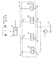
- a pressure oil discharged from a hydraulic pump 1 is supplied to a first chamber 31 and a second chamber 3 2 of a hydraulic equipment 3 through a first meter-in valve 2 1 and a second meter-in valve 2 2 , respectively, the meter-in valves 2 1 , 2 2 being two-way valves;
- the pressure oil having entered the first chamber 3 1 and the second chamber 3 2 is discharged into a tank 5 through a first meter-out valve 4 1 and a second meter-out valve 4 2 , respectively, the meter-out valves 4 1' 4 2 being two-way valves; in case that both of the first meter-in valve 2 1 and the second meter-out valve 4 2 are opened, the pressure oil is supplied to the first chamber 3 1 of the hydraulic equipment 3, while the pressure oil having entered the second chamber 3 2 of the equipment 3 is discharged from the second chamber 3 2 of the equipment 3 into the tank 5; and, in
- each of the valves described above is constructed of a pilot operated valve; and further comprised are a first and a second pilot valve, which first pilot valve conducts directional controls of the first meter-in valve 2 1 and the second meter-out valve 4 2 , and which second pilot valve conducts directional controls of the second meter-out valve 2 2 and the first meter-out valve 4 1 .
- a power shovel there are employed at least six hydraulic equipments comprising: a boom derricking cylinder, an arm hydraulic cylinder, a bucket hydraulic cylinder, a swing hydraulic motor, a left-hand traveling hydraulic motor and a right-hand traveling hydraulic motor, to which hydraulic equipments the pressure oil is supplied through four valves.
- the power shovel requires at least 24 valves and 12 pilot valves in operation.
- a valve housing 6 of the control valve system it is required for a valve housing 6 of the control valve system: to have in the interior thereof four valves comprising the first meter-in valve 2 1 , the second meter-in valve 2 2 , the first meter-out valve 4 1 and the second meter-out valve 4 2 ; and to form therein two pump ports 7 1 , 7 2 , two tank ports 8 1' 8 2' four additional ports 9 1 , 9 2 , 9 3 , 9 4 , the first and the second pilot valve, and pilot passages communicating with these pilot valves.
- valve housing 6 of the control valve system of the power shovel it is required for the valve housing 6 of the control valve system of the power shovel to have: 24 valves, 12 pilot valves, a plurality of the pump port passages, a plurality of the tank port passages, a plurality of the additional port passages and the pilot passages, which causes the valve housing 6 to be a large sized one.
- the valve housing 6 of the pilot operated control valve system it is very cumbersome to form each of the above port passages.
- the present invention was made. Consequently, it is an object of the present invention to provide a small-sized pilot operated control valve system requiring a minimum mounting space thereof, in which system: a plurality of valves are employed to control a hydraulic equipment, for example such as a hydraulic cylinder; a required number of each of the above valves is reduced; and there is no fear that the plurality of the valves interfere with each other in operation.
- a pilot operated control valve system comprising: a valve housing which is provided with a predetermined lateral width, a predetermined longitudinal width and a predetermined height, and assumes a substantially rectangular parallelepiped form; a first and a second pump port passage so formed in the valve housing as to have the same height, as to be parallelly spaced apart from each other in the longitudinal width direction of the.valve housing and as to horizontally extend in the lateral width direction of the valve housing; a tank port passage so formed in the val ' .e housing as to be disposed in a lower portion of the valve housing,' as to be disposed in a central position of the longitudinal width of the valve housing and as to horizontally extend in the lateral width direction of the valve housing; a pilot tank port passage so formed in the vale housing as to be disposed in central position of both of the height direction and the longitudinal width direction of the valve housing and as to horizontally extend in the lateral width direction of the valve housing;
- the above objects of the present invention are accomplished by providing: the pilot operated control valve system for controlling the hydraulic equipment of the first embodiment, wherein: the pilot operated control valve system is constructed of a plurality of control valve units for controlling a plurality of hydraulic equipments, the plurality of the control valve units being connected with each other in the lateral width direction of the valve housing of the control valve system.
- each of the first meter-in valve, the first meter-out valve, the first pilot valve, the second meter-in valve, the second meter-out valve and the second pilot valve is so formed in the valve housing of the pilot operated control valve system: as to horizontally extend in the longitudinal width direction of the valve housing to open into one of the opposite side surfaces of the valve housing perpendicular to the longitudinal width direction thereof; and as not to be aligned with each other in the height direction and the lateral width direction of the valve housing.
- each of the first and the second pump port passage, tank port passage and the pilot tank port passage is so formed in the valve housing of the control valve system as not to be aligned with each other in both of the height direction and the longitudinal width direction of the valve housing and as to horizontally extend in the lateral width direction of the valve housing, it is possible to sequentially mount each of the first and the second meter-in valve, first and the second meter-out valve, and the first and the second pilot valve in the valve housing so as to be spaced apart from each other in the lateral width direction of the valve housing.
- valve housing of the pilot operated control valve system of the present invention it is not required for the valve housing of the pilot operated control valve system of the present invention to additionally form any of the first and the second pump port passage, tank port passage and pilot tank port passage therein.
- valve housing of the pilot operated control valve system of the present invention it is required for the valve housing of the pilot operated control valve system of the present invention to form only the required number of each of the first and the second port passage in the valve housing, which reduces machining steps of the valve housing in manufacturing.
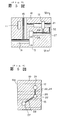
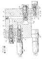
- a valve housing 10 of a pilot operated control valve system of the present invention has a predetermined lateral width, a predetermined longitudinal width and a predetermined height, and assumes a rectangular parallelepiped form.
- a first pump port passage 11 and a second pump port passage 12 which communicate with a hydraulic pump (not shown), are parallel to each other and horizontally extend in the lateral width direction of the valve housing 10 to open into an end surface 10a of the valve housing 10, which end surface 10a is perpendicular to the lateral width direction of the valve housing 10.
- a tank port passage 13 is so formed in the valve housing 10 as to be disposed in a lower portion of the valve housing 10, as to be disposed in a central position of the longitudinal width of the valve housing 10, as to horizontally extend in the lateral width direction of the valve housing 10 and as to communicate with a drain tank (not shown) to open into the end surface 10a of the valve housing 10.
- a first port passage 14 and a second port passage 15 are so formed in the valve housing 10 as not to be aligned with each other in both of the lateral width direction and the longitudinal width direction of the valve housing 10, as to extend vertically to open into an upper surface 10b of the valve housing 10 and as to communicate with a first pressure chamber 16 1 and a second pressure chamber 16 2 of a hydraulic equipment 16, respectively.
- the first port passage 14 and the second port passage 15 are so formed in the valve housing 10 as not to interfere with any of the first pump port passage 11, second pump port passage 12 and the tank port passage 13.
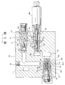
- a first meter-in valve receiving bore 17 and a first meter-out valve receiving bore 18 are so formed as to open into a side surface 10c of the valve housing 10 perpendicular to the longitudinal width direction of the valve housing 10, as not to be aligned with each other in the height direction and the lateral width direction of the valve housing 10, as to horizontally extend in the longitudinal width direction of the valve housing 10.
- the first meter-in valve receiving bore 17 is so disposed in the upper portion of the valve housing 10 as to penetrate the first pump port passage 11, as to communicate with the first port passage 14 and as to receive a first meter-in valve 19 therein to selectively shut off the first pump port passage 11 from the first port passage 14.
- the first meter-out valve receiving bore 18 is so disposed in the lower portion of the valve housing 10 as to open into the tank port passage 13, as to communicate with the second port passage 15 and as to receive a first meter-out valve 20 therein to selectively shut off the tank port passage 13 from the second port passage 15.
- a second meter-in valve receiving bore 21 and a second meter-out valve receiving bore 22 are so formed as to open into the other side surface 10d of the valve housing 10 perpendicular to the longitudinal width direction of the valve housing 10, as not to be aligned with each other in the height direction and the lateral width direction of the valve housing 10, as to horizontally extend in the longitudinal width direction of the valve housing 10.
- the second meter-in valve receiving bore 21 is so disposed in the upper portion of the valve housing 10 as to be aligned with the first meter-out valve receiving bore 18 in the lateral width direction of the valve housing 10, as to penetrate the second pump port passage 12, as to communicate with the second port passage 15 and as to receive a second meter-in valve 23 therein to selectively shut off the second pump port passage 12 from the second port passage 15.
- the second meter-out valve receiving bore 22 is so disposed in the lower portion of the valve housing 10 as to be aligned with the first meter-in valve receiving bore 17 in the lateral width direction of the valve housing 10, as to open into the tank port passage 13, as to communicate with the first port passage 14 and as to receive a second meter-out valve 24 therein to selectively shut off the tank port passage 13 from the first port passage 14.
- pilot tank port passage 25 which extends horizontally in the lateral width direction.of the valve housing 10 to open into the end surface 10a of the valve housing 10.
- the pilot tank port passage 25 is disposed in a position above the tank port passage 13 and extends parallel thereto.
- a first pilot valve receiving bore 26 which is so arranged: as to be disposed in a position under the first meter-in valve receiving bore 17; as to be similar to the pilot tank port passage 25 in height and to open into a side surface 10c of the valve housing 10, the side surface 10c being perpendicular to the longitudinal width direction of the valve housing 10; as to horizontally extend in the longitudinal width direction of the valve housing 10; and as not to be aligned with both of the first pilot valve receiving bore 26 and the second port passage 15 in the lateral width direction of the valve housing 10.
- a second pilot valve receiving bore 27 is so formed in the valve housing 10: as to be disposed in a lower portion of the valve housing 10; as to be similar to the pilot tank port passage 25 in height; as to open into the other side surface 10d of the valve housing 10; as to horizontally extend in the longitudinal width direction of the valve housing 10; and as not to be aligned with both of the second pilot valve receiving bore 27 and the first port passage 14 in the lateral width direction of the valve housing 10.
- the first pilot valve receiving bore 26 communicates with the pilot tank port passage 25 and further communicates with the first meter-in valve receiving bore 17, first meter-out valve receiving bore 18 and the first pump port passage 11 through a first oil hole 28, a second oil hole 29 and a third oil hole 30.
- a first pilot valve is inserted into the first pilot valve receiving bore 26 of the valve housing 10 as shown in Fig. 2.
- the second pilot valve receiving bore 27 communicates with the pilot tank port passage 25 and further communicates with the second meter-in valve receiving bore 21, second meter-out valve receiving bore 22 and the second pump port passage 12 through a first oil hole 32, a second oil hole 33 and a third oil hole 34.
- a second pilot valve 35 is inserted into the second pilot valve receiving bore 27 of the valve housing 10.
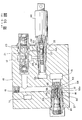
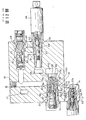
- each of the first meter-in valve 19 and the second meter-in valve 21 is so constructed that: an inlet port 41 is formed in a sleeve-like element 40; a spool 42 is inserted into the sleeve-like element 40 to selectively shut off and open the inlet port 41, the spool being so positioned as to normally shut off the inlet port 41 under the influence of a resilient force exerted by a spring 43 and as to open the inlet port 41 when subjected to a predetermined pilot pressure developed in a pressure chamber 44.
- each of the first meter-out valve 20 and the second meter-out valve 24 is so constructed that: an inlet port 51 is formed in a sleeve-like element 50; a poppet 52 for selectively shut off the inlet port 51 from the tank port passage 13 is inserted into the sleeve-like element 50; the inlet port 51 communicates with a back-pressure chamber 57 through a variable aperture 56 which is constructed of a slit groove 53 and a spool 55 having been inserted into an axial bore 54 of the sleeve-like element 50, to develop a pressure difference across the variable aperture 56; and a spring 58 is interposed between the spool 55 and a bottom portion of the axial bore 54 to normally bring the poppet 52 to its shut-off condition.
- each of sleeve-like elements 60 of the first pilot valve 31 and the second pilot valve 35 are formed: an inlet port 61, an outlet port 62 and a drain port 63.
- a spool 64 for selectively shutting off the inlet port 61 from the outlet port 62 is integrally formed with a poppet 65 for selectively shutting off the drain port 63 from the pilot tank port passage 25, while inserted into the sleeve-like element 60.
- Each of the spool 64 and the poppet 65 is operated by means of a solenoid 66.
- the inlet port 61 communicates with the first pump port passage 11 and the second pump port passage 12 through the third oil hole 30 and 34, respectively.
- the outlet port 62 communicates with the pressure chamber 44 of each of the first meter-in valve 19 and the second meter-in valve 21 through the first oil holes 28 and 32, while the drain port 63 communicates with the back-pressure chamber 57 of each of the first meter-out valve 20 and the second meter-out valve 24 through the second oil holes 29 and 33.
- the pilot operated control valve system of the present invention has the above construction so that, when the inlet port 61 communicates with the outlet port 62 by displacing the spool 64 and the poppet 65 by means of a solenoid 66 of each of the first pilot valve 31 and the second pilot valve 35 while the drain port 63 communicates with the pilot tank port passage 25, a pressure oil discharged from the tank port passage 13 is supplied to the pressure chamber 44 of the first meter-in valve 19 or the second meter-in valve 21 to move the spool 42 to its communication position.
- an auxiliary valve housing 71 is mounted on the valve housing 10 in a position under the second meter-out valve 24 provided in a lower portion of the valve housing 10 adjacent to the other side surface thereof perpendicular to the longitudinal width direction of the valve housing 10.
- the auxiliary valve housing 71 is provided with an auxiliary second pilot valve 70 which is similar to the second pilot valve 35 in shape.
- the drain port 63 of the auxiliary second pilot valve 70 communicates with the back-pressure chamber 57 of the second meter-out valve 24 through oil holes 72, 73.
- the second pilot valve 35 may have a construction provided with the spool 64 only, which spool 64 selectively shuts off the inlet port 61 from the outlet port 62.
- pilot operated control valve system of the present invention having the above construction, it is possible to control the second meter-in valve 21 by means of the second pilot valve 35 and to control the second meter-out valve 24 by means of the auxiliary second pilot valve 70.
- a first auxiliary pilot valve 70' having the same construction as that of the second auxiliary pilot valve 70 is mounted in the valve housing 10 in a position under the first meter-out valve 20 mounted in the valve housing 10 to control the first meter-out valve 20 by means of the first auxiliary pilot valve 70'; and the first pilot valve 31 has a construction provided with a spool 64 only, which spool 64 selectively shuts off the inlet port 61 from the outlet port 62 to control the first meter-in valve 19 only.
Landscapes
- Engineering & Computer Science (AREA)
- Physics & Mathematics (AREA)
- Fluid Mechanics (AREA)
- Mechanical Engineering (AREA)
- General Engineering & Computer Science (AREA)
- Fluid-Pressure Circuits (AREA)
- Valve Housings (AREA)
Applications Claiming Priority (2)
| Application Number | Priority Date | Filing Date | Title |
|---|---|---|---|
| JP44104/88 | 1988-02-29 | ||
| JP63044104A JP2559613B2 (ja) | 1988-02-29 | 1988-02-29 | 操作弁装置 |
Publications (3)
| Publication Number | Publication Date |
|---|---|
| EP0360873A1 true EP0360873A1 (de) | 1990-04-04 |
| EP0360873A4 EP0360873A4 (en) | 1990-09-19 |
| EP0360873B1 EP0360873B1 (de) | 1993-06-02 |
Family
ID=12682306
Family Applications (1)
| Application Number | Title | Priority Date | Filing Date |
|---|---|---|---|
| EP89902826A Expired - Lifetime EP0360873B1 (de) | 1988-02-29 | 1989-02-28 | Steuerventilanordnung mit vorsteuerung |
Country Status (5)
| Country | Link |
|---|---|
| US (1) | US5040565A (de) |
| EP (1) | EP0360873B1 (de) |
| JP (1) | JP2559613B2 (de) |
| KR (1) | KR900700767A (de) |
| WO (1) | WO1989008198A1 (de) |
Cited By (3)
| Publication number | Priority date | Publication date | Assignee | Title |
|---|---|---|---|---|
| EP0941432A4 (de) * | 1996-12-03 | 2003-01-29 | Kinetics Fluid Systems | Baublöcke für ein integriertes gaspaneel |
| US7178556B2 (en) | 2003-08-07 | 2007-02-20 | Parker-Hannifin Corporation | Modular component connector substrate assembly system |
| CN109931314A (zh) * | 2019-03-22 | 2019-06-25 | 中国铁建重工集团有限公司 | 液压系统 |
Families Citing this family (4)
| Publication number | Priority date | Publication date | Assignee | Title |
|---|---|---|---|---|
| KR930007952B1 (ko) * | 1989-03-24 | 1993-08-25 | 히다찌 겐끼 가부시기가이샤 | 밸브장치 및 유압구동장치 |
| WO2008048551A2 (en) * | 2006-10-17 | 2008-04-24 | Swagelok Company | Manifold arrangement |
| CN101943188B (zh) * | 2010-04-29 | 2013-08-21 | 上海人豪液压技术有限公司 | 采用组合式法兰控制盖板的紧凑型二通插装阀 |
| CN106122141B (zh) * | 2016-05-31 | 2018-04-03 | 上海人豪液压技术有限公司 | 采用模块化可配组插装阀rhcv组合的电液控制终端 |
Family Cites Families (10)
| Publication number | Priority date | Publication date | Assignee | Title |
|---|---|---|---|---|
| US2984257A (en) * | 1957-07-10 | 1961-05-16 | Automatic Switch Co | Pilot-operated four-way valve |
| US3556144A (en) * | 1969-11-10 | 1971-01-19 | Nordberg Manufacturing Co | Directional control valve and method of making |
| JPS6043701A (ja) * | 1983-08-22 | 1985-03-08 | Hitachi Ltd | デイジタル誤差検出器 |
| LU85774A1 (fr) * | 1985-02-13 | 1985-07-24 | Hydrolux Sarl | Hydraulischer steuerblock |
| JPS6213802A (ja) * | 1985-07-09 | 1987-01-22 | Ishikawajima Harima Heavy Ind Co Ltd | パイロツト流体回路 |
| JPS6213803A (ja) * | 1985-07-09 | 1987-01-22 | Ishikawajima Harima Heavy Ind Co Ltd | 積層式流体切換弁 |
| JPS6440702A (en) * | 1987-08-05 | 1989-02-13 | Hitachi Construction Machinery | Valve device |
| JPH0643701U (ja) * | 1992-11-06 | 1994-06-10 | 神鋼電機株式会社 | 電空変換弁増幅器 |
| JPH06213802A (ja) * | 1993-01-18 | 1994-08-05 | Toyo Kensetsu Kk | 植物プランクトン測定装置 |
| JPH06213803A (ja) * | 1993-01-21 | 1994-08-05 | Hitachi Ltd | 高感度検出方法及びその装置 |
-
1988
- 1988-02-29 JP JP63044104A patent/JP2559613B2/ja not_active Expired - Lifetime
-
1989
- 1989-02-28 WO PCT/JP1989/000205 patent/WO1989008198A1/ja not_active Ceased
- 1989-02-28 EP EP89902826A patent/EP0360873B1/de not_active Expired - Lifetime
- 1989-02-28 US US07/425,174 patent/US5040565A/en not_active Expired - Fee Related
- 1989-10-26 KR KR1019890701981A patent/KR900700767A/ko not_active Withdrawn
Non-Patent Citations (1)
| Title |
|---|
| See references of WO8908198A1 * |
Cited By (4)
| Publication number | Priority date | Publication date | Assignee | Title |
|---|---|---|---|---|
| EP0941432A4 (de) * | 1996-12-03 | 2003-01-29 | Kinetics Fluid Systems | Baublöcke für ein integriertes gaspaneel |
| US7178556B2 (en) | 2003-08-07 | 2007-02-20 | Parker-Hannifin Corporation | Modular component connector substrate assembly system |
| CN109931314A (zh) * | 2019-03-22 | 2019-06-25 | 中国铁建重工集团有限公司 | 液压系统 |
| CN109931314B (zh) * | 2019-03-22 | 2024-05-14 | 中国铁建重工集团股份有限公司 | 液压系统 |
Also Published As
| Publication number | Publication date |
|---|---|
| WO1989008198A1 (fr) | 1989-09-08 |
| KR900700767A (ko) | 1990-08-16 |
| US5040565A (en) | 1991-08-20 |
| JPH01220704A (ja) | 1989-09-04 |
| JP2559613B2 (ja) | 1996-12-04 |
| EP0360873A4 (en) | 1990-09-19 |
| EP0360873B1 (de) | 1993-06-02 |
Similar Documents
| Publication | Publication Date | Title |
|---|---|---|
| US4170214A (en) | Hydraulic valve module | |
| EP1434943B1 (de) | Mehrfachhydraulikventilanordnung mit einem monolithischen block | |
| KR100576930B1 (ko) | 유압모터로의 유체 흐름을 조절하기 위한 세개의 전동유압밸브를 가지는 유압 시스템 | |
| US6964281B2 (en) | Multiple hydraulic spool valve assembly with a monolithic body | |
| US5794651A (en) | Valve adaptor cap | |
| EP0846872A1 (de) | Steuerventil-Verteilerplatte | |
| US5115835A (en) | Stacked type hydraulic control valve system | |
| US5040565A (en) | Pilot operated control valve system | |
| US5046400A (en) | Control valve system | |
| CN114729707B (zh) | 多重控制阀装置 | |
| JPH0495601A (ja) | アクチュエータ駆動回路における切換弁のパイロット圧力制御回路 | |
| EP0358778B1 (de) | Vorgesteuerte ventilanordnung | |
| US5188147A (en) | Pressure compensating type hydraulic valve | |
| EP0404956A1 (de) | Zufuhr von öl unter druck für den zylinder einer maschine | |
| EP0425684B1 (de) | Ventilanordnung und hydraulisches antriebssystem | |
| JP3502164B2 (ja) | 多連方向切換弁装置 | |
| KR100499285B1 (ko) | 토목건설기계용 유압장치의 파일럿절환밸브 | |
| JP2544786Y2 (ja) | 操作弁装置 | |
| JP2766072B2 (ja) | 弁装置および油圧駆動装置 | |
| JPH04136511A (ja) | 油圧回路に用いる操作弁装置 | |
| JPH07238902A (ja) | 方向制御弁の圧油排出構造 | |
| JPH04136512A (ja) | 油圧回路に用いる操作弁装置 | |
| JPH0656503U (ja) | 圧油供給装置 | |
| JPS62188805A (ja) | 油圧制御装置 |
Legal Events
| Date | Code | Title | Description |
|---|---|---|---|
| PUAI | Public reference made under article 153(3) epc to a published international application that has entered the european phase |
Free format text: ORIGINAL CODE: 0009012 |
|
| 17P | Request for examination filed |
Effective date: 19891026 |
|
| AK | Designated contracting states |
Kind code of ref document: A1 Designated state(s): DE SE |
|
| A4 | Supplementary search report drawn up and despatched |
Effective date: 19900731 |
|
| AK | Designated contracting states |
Kind code of ref document: A4 Designated state(s): DE SE |
|
| 17Q | First examination report despatched |
Effective date: 19911126 |
|
| GRAA | (expected) grant |
Free format text: ORIGINAL CODE: 0009210 |
|
| AK | Designated contracting states |
Kind code of ref document: B1 Designated state(s): DE SE |
|
| REF | Corresponds to: |
Ref document number: 68906842 Country of ref document: DE Date of ref document: 19930708 |
|
| PLBE | No opposition filed within time limit |
Free format text: ORIGINAL CODE: 0009261 |
|
| STAA | Information on the status of an ep patent application or granted ep patent |
Free format text: STATUS: NO OPPOSITION FILED WITHIN TIME LIMIT |
|
| 26N | No opposition filed | ||
| EAL | Se: european patent in force in sweden |
Ref document number: 89902826.0 |
|
| PGFP | Annual fee paid to national office [announced via postgrant information from national office to epo] |
Ref country code: SE Payment date: 19980218 Year of fee payment: 10 |
|
| PGFP | Annual fee paid to national office [announced via postgrant information from national office to epo] |
Ref country code: DE Payment date: 19980306 Year of fee payment: 10 |
|
| PG25 | Lapsed in a contracting state [announced via postgrant information from national office to epo] |
Ref country code: SE Free format text: LAPSE BECAUSE OF NON-PAYMENT OF DUE FEES Effective date: 19990301 |
|
| EUG | Se: european patent has lapsed |
Ref document number: 89902826.0 |
|
| PG25 | Lapsed in a contracting state [announced via postgrant information from national office to epo] |
Ref country code: DE Free format text: LAPSE BECAUSE OF NON-PAYMENT OF DUE FEES Effective date: 19991201 |
|
| EUG | Se: european patent has lapsed |
Ref document number: 89902826.0 |