EP0360837B1 - Zellzuchtreaktor mit drei kammern, die von hydrophoben und hydrophilen membranen begrenzt sind - Google Patents
Zellzuchtreaktor mit drei kammern, die von hydrophoben und hydrophilen membranen begrenzt sind Download PDFInfo
- Publication number
- EP0360837B1 EP0360837B1 EP88906492A EP88906492A EP0360837B1 EP 0360837 B1 EP0360837 B1 EP 0360837B1 EP 88906492 A EP88906492 A EP 88906492A EP 88906492 A EP88906492 A EP 88906492A EP 0360837 B1 EP0360837 B1 EP 0360837B1
- Authority
- EP
- European Patent Office
- Prior art keywords
- cell
- nutrient medium
- bioreactor
- cells
- membrane
- Prior art date
- Legal status (The legal status is an assumption and is not a legal conclusion. Google has not performed a legal analysis and makes no representation as to the accuracy of the status listed.)
- Expired - Lifetime
Links
- 239000012528 membrane Substances 0.000 title claims abstract description 165
- 230000002209 hydrophobic effect Effects 0.000 title claims description 39
- 230000010261 cell growth Effects 0.000 title description 2
- 210000004027 cell Anatomy 0.000 claims abstract description 246
- 235000015097 nutrients Nutrition 0.000 claims abstract description 222
- 239000007789 gas Substances 0.000 claims abstract description 110
- 239000001301 oxygen Substances 0.000 claims abstract description 73
- 229910052760 oxygen Inorganic materials 0.000 claims abstract description 73
- QVGXLLKOCUKJST-UHFFFAOYSA-N atomic oxygen Chemical compound [O] QVGXLLKOCUKJST-UHFFFAOYSA-N 0.000 claims abstract description 72
- 210000004408 hybridoma Anatomy 0.000 claims abstract description 16
- 125000006850 spacer group Chemical group 0.000 claims description 44
- 238000004519 manufacturing process Methods 0.000 claims description 22
- 239000000835 fiber Substances 0.000 claims description 18
- 238000000034 method Methods 0.000 claims description 16
- 238000010899 nucleation Methods 0.000 claims description 16
- 239000007788 liquid Substances 0.000 claims description 14
- 230000008569 process Effects 0.000 claims description 11
- 239000011148 porous material Substances 0.000 claims description 10
- 238000009792 diffusion process Methods 0.000 claims description 9
- 210000001822 immobilized cell Anatomy 0.000 claims description 6
- 239000012982 microporous membrane Substances 0.000 claims description 2
- 238000011084 recovery Methods 0.000 claims 2
- 230000003248 secreting effect Effects 0.000 claims 1
- 238000013461 design Methods 0.000 abstract description 27
- 230000006870 function Effects 0.000 abstract description 10
- 239000000203 mixture Substances 0.000 abstract description 10
- 238000003306 harvesting Methods 0.000 abstract description 8
- 210000004962 mammalian cell Anatomy 0.000 abstract description 8
- 235000016709 nutrition Nutrition 0.000 abstract description 2
- 239000002609 medium Substances 0.000 description 172
- 239000000047 product Substances 0.000 description 52
- CURLTUGMZLYLDI-UHFFFAOYSA-N Carbon dioxide Chemical compound O=C=O CURLTUGMZLYLDI-UHFFFAOYSA-N 0.000 description 30
- 239000012510 hollow fiber Substances 0.000 description 30
- 239000000463 material Substances 0.000 description 28
- 239000010410 layer Substances 0.000 description 26
- 239000002699 waste material Substances 0.000 description 21
- 239000000306 component Substances 0.000 description 19
- 229910002092 carbon dioxide Inorganic materials 0.000 description 15
- 239000001569 carbon dioxide Substances 0.000 description 14
- 239000007787 solid Substances 0.000 description 12
- WQZGKKKJIJFFOK-GASJEMHNSA-N Glucose Natural products OC[C@H]1OC(O)[C@H](O)[C@@H](O)[C@@H]1O WQZGKKKJIJFFOK-GASJEMHNSA-N 0.000 description 11
- 230000001413 cellular effect Effects 0.000 description 11
- 239000008103 glucose Substances 0.000 description 11
- 238000005086 pumping Methods 0.000 description 11
- 238000000108 ultra-filtration Methods 0.000 description 11
- 238000010276 construction Methods 0.000 description 10
- 238000013459 approach Methods 0.000 description 9
- 238000006243 chemical reaction Methods 0.000 description 8
- 230000008901 benefit Effects 0.000 description 7
- 230000001419 dependent effect Effects 0.000 description 7
- 239000004809 Teflon Substances 0.000 description 6
- 229920006362 Teflon® Polymers 0.000 description 6
- 238000010586 diagram Methods 0.000 description 6
- 230000036512 infertility Effects 0.000 description 6
- 102000004169 proteins and genes Human genes 0.000 description 6
- 108090000623 proteins and genes Proteins 0.000 description 6
- 239000000470 constituent Substances 0.000 description 5
- 238000007792 addition Methods 0.000 description 4
- 239000000853 adhesive Substances 0.000 description 4
- 230000001070 adhesive effect Effects 0.000 description 4
- 230000000740 bleeding effect Effects 0.000 description 4
- 238000004113 cell culture Methods 0.000 description 4
- 239000012141 concentrate Substances 0.000 description 4
- 238000000855 fermentation Methods 0.000 description 4
- 230000004151 fermentation Effects 0.000 description 4
- 239000012466 permeate Substances 0.000 description 4
- 230000009467 reduction Effects 0.000 description 4
- 230000001105 regulatory effect Effects 0.000 description 4
- 238000007789 sealing Methods 0.000 description 4
- 238000011218 seed culture Methods 0.000 description 4
- 229920004934 Dacron® Polymers 0.000 description 3
- MYMOFIZGZYHOMD-UHFFFAOYSA-N Dioxygen Chemical compound O=O MYMOFIZGZYHOMD-UHFFFAOYSA-N 0.000 description 3
- 230000019522 cellular metabolic process Effects 0.000 description 3
- 238000011109 contamination Methods 0.000 description 3
- 230000001627 detrimental effect Effects 0.000 description 3
- 230000007613 environmental effect Effects 0.000 description 3
- 239000003102 growth factor Substances 0.000 description 3
- 238000010348 incorporation Methods 0.000 description 3
- 238000012423 maintenance Methods 0.000 description 3
- 230000004048 modification Effects 0.000 description 3
- 238000012986 modification Methods 0.000 description 3
- 238000006213 oxygenation reaction Methods 0.000 description 3
- 239000005020 polyethylene terephthalate Substances 0.000 description 3
- 238000011027 product recovery Methods 0.000 description 3
- 238000000746 purification Methods 0.000 description 3
- 230000036647 reaction Effects 0.000 description 3
- 230000035939 shock Effects 0.000 description 3
- XLYOFNOQVPJJNP-UHFFFAOYSA-N water Substances O XLYOFNOQVPJJNP-UHFFFAOYSA-N 0.000 description 3
- 238000004804 winding Methods 0.000 description 3
- 239000004743 Polypropylene Substances 0.000 description 2
- 230000009471 action Effects 0.000 description 2
- 238000005273 aeration Methods 0.000 description 2
- 230000001580 bacterial effect Effects 0.000 description 2
- 230000015556 catabolic process Effects 0.000 description 2
- 238000004891 communication Methods 0.000 description 2
- RKTYLMNFRDHKIL-UHFFFAOYSA-N copper;5,10,15,20-tetraphenylporphyrin-22,24-diide Chemical compound [Cu+2].C1=CC(C(=C2C=CC([N-]2)=C(C=2C=CC=CC=2)C=2C=CC(N=2)=C(C=2C=CC=CC=2)C2=CC=C3[N-]2)C=2C=CC=CC=2)=NC1=C3C1=CC=CC=C1 RKTYLMNFRDHKIL-UHFFFAOYSA-N 0.000 description 2
- 238000012864 cross contamination Methods 0.000 description 2
- 210000004748 cultured cell Anatomy 0.000 description 2
- 238000011161 development Methods 0.000 description 2
- 238000005516 engineering process Methods 0.000 description 2
- 239000001963 growth medium Substances 0.000 description 2
- 238000010438 heat treatment Methods 0.000 description 2
- 230000016784 immunoglobulin production Effects 0.000 description 2
- 230000000670 limiting effect Effects 0.000 description 2
- 239000012533 medium component Substances 0.000 description 2
- 238000002156 mixing Methods 0.000 description 2
- 230000008520 organization Effects 0.000 description 2
- 239000011236 particulate material Substances 0.000 description 2
- -1 polypropylene Polymers 0.000 description 2
- 229920001155 polypropylene Polymers 0.000 description 2
- 230000002829 reductive effect Effects 0.000 description 2
- 230000008439 repair process Effects 0.000 description 2
- 230000000717 retained effect Effects 0.000 description 2
- 229920002379 silicone rubber Polymers 0.000 description 2
- 239000004945 silicone rubber Substances 0.000 description 2
- 239000002356 single layer Substances 0.000 description 2
- 235000000346 sugar Nutrition 0.000 description 2
- 231100000331 toxic Toxicity 0.000 description 2
- 230000002588 toxic effect Effects 0.000 description 2
- 238000012546 transfer Methods 0.000 description 2
- 238000009736 wetting Methods 0.000 description 2
- 108091003079 Bovine Serum Albumin Proteins 0.000 description 1
- 241000238631 Hexapoda Species 0.000 description 1
- JVTAAEKCZFNVCJ-UHFFFAOYSA-M Lactate Chemical compound CC(O)C([O-])=O JVTAAEKCZFNVCJ-UHFFFAOYSA-M 0.000 description 1
- 108010071390 Serum Albumin Proteins 0.000 description 1
- 102000007562 Serum Albumin Human genes 0.000 description 1
- 230000002411 adverse Effects 0.000 description 1
- 230000033228 biological regulation Effects 0.000 description 1
- 230000015572 biosynthetic process Effects 0.000 description 1
- 238000004364 calculation method Methods 0.000 description 1
- 238000012832 cell culture technique Methods 0.000 description 1
- 230000032823 cell division Effects 0.000 description 1
- 230000008614 cellular interaction Effects 0.000 description 1
- 229910010293 ceramic material Inorganic materials 0.000 description 1
- 230000008859 change Effects 0.000 description 1
- 238000004140 cleaning Methods 0.000 description 1
- 230000001143 conditioned effect Effects 0.000 description 1
- 230000001276 controlling effect Effects 0.000 description 1
- 238000005336 cracking Methods 0.000 description 1
- 238000012258 culturing Methods 0.000 description 1
- 230000008021 deposition Effects 0.000 description 1
- 238000000502 dialysis Methods 0.000 description 1
- 238000007599 discharging Methods 0.000 description 1
- 230000009977 dual effect Effects 0.000 description 1
- 239000012894 fetal calf serum Substances 0.000 description 1
- 238000001914 filtration Methods 0.000 description 1
- 239000012530 fluid Substances 0.000 description 1
- 239000007792 gaseous phase Substances 0.000 description 1
- 150000002303 glucose derivatives Chemical class 0.000 description 1
- 239000003292 glue Substances 0.000 description 1
- 230000036541 health Effects 0.000 description 1
- 239000005556 hormone Substances 0.000 description 1
- 229940088597 hormone Drugs 0.000 description 1
- 230000004941 influx Effects 0.000 description 1
- 239000004615 ingredient Substances 0.000 description 1
- 230000002401 inhibitory effect Effects 0.000 description 1
- 238000013383 initial experiment Methods 0.000 description 1
- 229910052500 inorganic mineral Inorganic materials 0.000 description 1
- 238000009434 installation Methods 0.000 description 1
- 230000002452 interceptive effect Effects 0.000 description 1
- 238000002955 isolation Methods 0.000 description 1
- 230000002147 killing effect Effects 0.000 description 1
- 150000002632 lipids Chemical class 0.000 description 1
- 230000007774 longterm Effects 0.000 description 1
- 230000002503 metabolic effect Effects 0.000 description 1
- 230000037353 metabolic pathway Effects 0.000 description 1
- 239000011707 mineral Substances 0.000 description 1
- 238000012544 monitoring process Methods 0.000 description 1
- 235000006180 nutrition needs Nutrition 0.000 description 1
- 230000036284 oxygen consumption Effects 0.000 description 1
- 238000012856 packing Methods 0.000 description 1
- 230000000737 periodic effect Effects 0.000 description 1
- 230000002572 peristaltic effect Effects 0.000 description 1
- 238000009428 plumbing Methods 0.000 description 1
- 229920002492 poly(sulfone) Polymers 0.000 description 1
- 229920000728 polyester Polymers 0.000 description 1
- 229920000642 polymer Polymers 0.000 description 1
- 238000012545 processing Methods 0.000 description 1
- 230000000069 prophylactic effect Effects 0.000 description 1
- 230000010349 pulsation Effects 0.000 description 1
- 230000003134 recirculating effect Effects 0.000 description 1
- 230000007363 regulatory process Effects 0.000 description 1
- 238000011160 research Methods 0.000 description 1
- 210000002345 respiratory system Anatomy 0.000 description 1
- 150000003839 salts Chemical class 0.000 description 1
- 238000005070 sampling Methods 0.000 description 1
- 229920006395 saturated elastomer Polymers 0.000 description 1
- 238000010008 shearing Methods 0.000 description 1
- 230000000087 stabilizing effect Effects 0.000 description 1
- 230000001954 sterilising effect Effects 0.000 description 1
- 239000000758 substrate Substances 0.000 description 1
- 150000008163 sugars Chemical class 0.000 description 1
- 230000009469 supplementation Effects 0.000 description 1
- 230000004083 survival effect Effects 0.000 description 1
- 230000001225 therapeutic effect Effects 0.000 description 1
- 230000035899 viability Effects 0.000 description 1
- 239000002912 waste gas Substances 0.000 description 1
- 239000000080 wetting agent Substances 0.000 description 1
Images


Classifications
-
- C—CHEMISTRY; METALLURGY
- C12—BIOCHEMISTRY; BEER; SPIRITS; WINE; VINEGAR; MICROBIOLOGY; ENZYMOLOGY; MUTATION OR GENETIC ENGINEERING
- C12M—APPARATUS FOR ENZYMOLOGY OR MICROBIOLOGY; APPARATUS FOR CULTURING MICROORGANISMS FOR PRODUCING BIOMASS, FOR GROWING CELLS OR FOR OBTAINING FERMENTATION OR METABOLIC PRODUCTS, i.e. BIOREACTORS OR FERMENTERS
- C12M29/00—Means for introduction, extraction or recirculation of materials, e.g. pumps
- C12M29/04—Filters; Permeable or porous membranes or plates, e.g. dialysis
-
- C—CHEMISTRY; METALLURGY
- C12—BIOCHEMISTRY; BEER; SPIRITS; WINE; VINEGAR; MICROBIOLOGY; ENZYMOLOGY; MUTATION OR GENETIC ENGINEERING
- C12M—APPARATUS FOR ENZYMOLOGY OR MICROBIOLOGY; APPARATUS FOR CULTURING MICROORGANISMS FOR PRODUCING BIOMASS, FOR GROWING CELLS OR FOR OBTAINING FERMENTATION OR METABOLIC PRODUCTS, i.e. BIOREACTORS OR FERMENTERS
- C12M23/00—Constructional details, e.g. recesses, hinges
- C12M23/24—Gas permeable parts
-
- C—CHEMISTRY; METALLURGY
- C12—BIOCHEMISTRY; BEER; SPIRITS; WINE; VINEGAR; MICROBIOLOGY; ENZYMOLOGY; MUTATION OR GENETIC ENGINEERING
- C12M—APPARATUS FOR ENZYMOLOGY OR MICROBIOLOGY; APPARATUS FOR CULTURING MICROORGANISMS FOR PRODUCING BIOMASS, FOR GROWING CELLS OR FOR OBTAINING FERMENTATION OR METABOLIC PRODUCTS, i.e. BIOREACTORS OR FERMENTERS
- C12M23/00—Constructional details, e.g. recesses, hinges
- C12M23/34—Internal compartments or partitions
Definitions
- This invention relates to bioreactors which can be used to enable cells to produce cell products, and particularly to enable hybridomas to produce monoclonal antibodies.
- the bioreactor system resembles a living organism in many ways. It has an enclosure in which cells can live, multiply, and produce; a circulating system for supplying water and nutrient and removing waste from the cells; a respiratory system for providing oxygen and removing carbon dioxide; and means for removing cell products and wastes from the system. The success of the whole system depends not only on how well each of the elements is designed but even more on how well they interact and coordinate with each other to maintain effective conditions for the production of cell products.
- Immobilized hybridoma cells in particular can produce their products virtually indefinitely in such bioreactors without disturbances related to the harvesting of products.
- adequate oxygenation of the cultured cells and removal of carbon dioxide has been a limiting factor in the development of efficient and economical designs.
- attachment dependent cells are attached on the outer surface of hollow fiber membranes, and derive their oxygen supply from an air or other oxygen carrier flowing on the inside of the fiber.
- the number of cells is limited to a monolayer on the available membrane surface, limiting the cell density to low levels.
- most cells are limited in their ability to survive the high oxygen tensions. If the applied gas pressure is too high, it may produce gas bubbles that will disrupt the cells or their attachment.
- the requirement that the cells attach to the surfaces requires that the membrane be hydrophilic, and thus susceptible to wetting by the nutrient, and passage of materials into and even through the pores, causing clogging and disruption of, the flow. This will dictate a high gas pressure to limit the rate of these phenomena, and damage to the cells will inevitably result.
- U.S. 4,201,845 is a Continuation-in-Part of 4,087,327, supra.
- the interior of hollow fiber membranes are used for oxygen transport into the cell reaction zone.
- the nutrient is again pumped transversely through the cell chamber, with the attendant problems.
- the difficulties with this teaching are the same as those noted above with respect to 3,997,396.
- U.S. Patent 4,537,860 teaches a cell reactor which employs an annular construction of porous cylinders of polymer or ceramic materials to confine cells, pump nutrient through the cell chamber (with all the attendant difficulties of through flow operations), and semipermeable, silicone rubber tubing to carry gas into, and to cause it to perfuse into, the cell chamber.
- the distance of the cells can be as much as 1 to 2 cm from the oxygen supply tube, and coupled with the properties of the silicone rubber tubing, leads to the requirement that the oxygen source be fed under such pressure that the supply tube passes gaseous phase into the reaction zone in order to provide adequately oxygen to the cell chamber, with attendant turbulence, high internal pressures and damage to the cells.
- This "sparger" approach leads to inadequate rates of oxygen uptake to assure cell productivity and even viability in substantial parts of the vessel.
- the cells are confined between two membranes which form a cell chamber, at least one of which is microporous and hydrophilic and permits the free passage of all nutrients as well as monoclonal antibodies and other cell products.
- the nutrient medium does not have to carry dissolved gases, so the medium which returns to the reservoir is cycled back to the bioreactor without having to pass through a separate, external gas exchanger. Nutrient medium is continuously added to the system and product and waste are continuously withdrawn at the same rates.
- the present invention includes several embodiments which solve the oxygen delivery and removal of carbon dioxide and other waste gases by incorporating a separate gas exchange compartment into an immobilized cell bioreactor thereby eliminating the need for a gas exchanger which is external to the bioreactor core.
- the central concept behind the design of these embodiments is that oxygen is passed through the bioreactor as air or another gas mixture, rather than dissolved in the nutrient medium. Oxygen diffuses directly into the cell space.
- the relatively high concentration of oxygen in air (or other appropriate gas mixture) as compared to that dissolved in the nutrient medium, and the low viscosity of gases as compared to liquids, allows a slow flow of air at low pressure to supply an abundance of oxygen to the cells.
- excess carbon dioxide is more rapidly removed as a gas than dissolved in the nutrient medium. Nutrient medium can thus be circulated much more slowly, resulting in a smaller, more efficient and economical bioreactor.
- the simplest embodiment interleaves a hydrophobic, microporous, membrane-bounded air chamber between two cell chambers in a layered membrane bioreactor.
- the cells are placed between a microporous hydrophilic membrane which separates them from the circulating nutrient medium and another, ultraporous membrane, this one hydrophobic, and separating them from a stream of appropriate gas.
- a mixture of air with about 5% of carbon dioxide seems desirable for most mammalian cell lines.
- Appropriate hydrophobic membranes of polysulfone, teflon or polypropylene are available commercially.
- a spacer screen is combined with or, alternatively, replaced with particulate support material for attachment dependent cells.
- any of these embodiments can be incorporated into either stacks of flat membranes or into a spiral-wound membrane format.
- the spiral can be formed in either an end-wound format or a center-wound format.
- Either configuration offers the advantages of simplicity of construction, compactness, low stress on cells and membranes, and low material and fabrication costs.
- the entire reactor component, in either configuration can be pre-packaged, offering great convenience and ease of use.
- the bioreactor of the present invention meets the nutritional and physical needs of hybridomas or mammalian cells, allows for the harvesting of products, and maintains sterile integrity of the system by combining several individual apparatus having separate functions into an integrated, functioning unit.
- the feed supply of the bioreactor assures the fulfillment of all cellular nutritional needs and the bleed or removal system removes wastes and products at any desired rate as appropriate for the culture.
- Nutrient medium bled from the circulation is passed through various steps to purify the antibody product. Removal of nutrient medium need not be constrained by cell growth rates since the cells of the bioreactor of the present invention are stationary and thus are not removed with the medium. Product recovery, therefore, does not interrupt production.
- the continuous feeding system for nutrient medium means that only small volumes of sterile liquids are handled. Likewise, continuous removal and concentration of product keep volumes small. This keeps costs and the possibility of contaminations at a minimum and maximizes ease of operation. Aseptic breaks in the nutrient medium flow maintain sterility and prevent cross contamination.
- the nutrient medium may contain expensive components. These can be conserved and recirculated in the bioreactor of the present invention through the employment of appropriate separatory and purification techniques, such as the inclusion of an ultrafiltration module in the bleed system. This module can also be used to concentrate the product in the nutrient medium before harvesting. Cells do not interfere with product collection since they are retained in the cell chambers by the microporous membranes.
- In-line nutrient medium heating obviates the need for an enclosing environmental chamber or at the least reduces the demands on an environmental chamber while the maintenance requirements and costs are low.
- the bioreactor of the present invention is a very versatile design which will support all types of cells producing all types of products. Both attachment independent and dependent cell lines are suitable for the layered membrane design, particularly hybridomas. All the materials employed in such reactors, including nutrients, products, and cellular waste, including proteins, lipids, sugars, salts, organic and inorganic constituents, and simple and complex products, particularly monoclonal antibodies, are all compatible with this bioreactor design.
- the residence time of the product is variable and can be adjusted to the needs of the specific cell line.
- Toxic, inhibitory, or unstable products can be removed rapidly.
- Stable, non-interfering products may remain in the system for a time and be concentrated prior to removal.
- each bioreactor unit and the ability of one nutrient medium preparation center to supply many bioreactors makes the bioreactor of the present invention adaptable to the production needs of any facility.
- the entire bioreactor is compact.
- bioreactor of the present invention integrates advantageous design features for every aspect of hybridoma or mammalian cell culture into a single integrated bioreactor unit. This unit is economical to operate, can be easily adapted to all cell line and product specifications and maximizes production.
- Figure 1 is a flow diagram showing the bioreactor system of the present invention as a whole, and illustrating the configuration and operation of the various elements thereof.
- Figure 2 is a cross sectional view showing the aseptic breaks used in the nutrient medium circulation system.
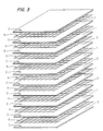
- Figure 3 is an exploded schematic diagram showing the membrane, spacer and chamber arrangement of a bioreactor core for one embodiment of the present invention.
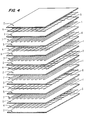
- Figure 4 is an exploded schematic diagram showing another embodiment of the membrane and chamber arrangement of a bioreactor core.
- the solid fiber spacer screen in the cell chamber is replaced by a hollow fiber spacer screen.
- Figure 5 is a cross-sectional diagram showing another embodiment of the membrane and chamber arrangement of a bioreactor core.
- the solid fiber spacer screen in the cell chamber is supplemented by particulate support material.
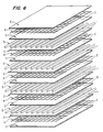
- FIG. 6 is a perspective diagram showing another embodiment of the membrane and chamber arrangement of a bioreactor core for a bioreactor having directly fed hollow fibers for gas exchange as part of the bioreactor core.
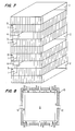
- Figure 7 is a perspective view of a stack bioreactor core for a bioreactor having cell chamber ports at the corners.
- Figure 8 is a top view of a stack bioreactor core for a bioreactor having cell chamber ports at the corners.
- Figure 9 is a cross-sectional schematic view of a spiral-wound bioreactor with a gas exchange chamber showing end-wound construction, the spacer screens in each chamber not shown for clarity.
- Figure 9a is a schematic detail showing the specific arrangement of the membranes and spacers of each layer of the spiral.
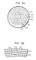
- Figure 10 is a cross-sectional schematic view of a spiral-wound bioreactor with a gas exchange chamber showing center-wound construction, the spacer screens in each chamber not shown for clarity.
- Figure 10a is a schematic detail showing the specific arrangement of the membranes and spacers of each layer of the spiral.
- the physical support structure for the cells in the bioreactor of the present invention is any of a variety of layered membrane enclosures which combine to form the bioreactor core or cell enclosure.
- the various types of bioreactor core structures will be described in further detail below.
- the basic design for the bioreactor core integrates the gas exchanger into the same structure as the cell enclosure reactor zone. This design will be referred to herein as a compartmentalized gas exchange chamber or a direct aeration bioreactor.
- This system is analogous to the tracheal system of insects since there is direct diffusion of gases across a membrane separating cells and air.
- the liquid surrounding the cells cannot pass through the hydrophobic membrane into the gas chamber, and the pressure of the gas mixture must be slightly less than that of the nutrient medium to prevent bubble formation in the cell chamber.
- the bioreactor of the present invention is made up of at least one reactor zone formed of porous sheet membranes, joined at their edges, which contains the cells.
- One of the membranes is hydrophilic, with a porosity suitable for the transport of nutrient into the reactor zone, and the transport of nutrient, cell products, and waste materials out of the zone.
- Nutrient is furnished to the reactor zone by diffusion through the hydrophilic membrane, at a rate suited to the cell metabolism, and preferably not much greater.
- the other membrane is hydrophobic and ultraporous.
- the pore size of the hydrophobic membranes range from about 0.005 to 0.1 ⁇ m, preferably from about 0.01 to 0.05 ⁇ m.
- Oxygen as such or more commonly in the form of air, and with possibly other additions, including minor amounts of carbon dioxide, for example, is supplied to the reactor zone through the membrane, where the oxygen diffuses into and through the nutrient and to the adjacent cells. If the pores are smaller than the low end of the above range, the pores restrict gas transport too much. On the other hand, if the pores are larger than the high end of the range, protein deposits and wetting agent constituents of the nutrient medium will gradually build up in the pores eventually allowing water and or nutrient medium to pass into the gas exchange chamber.
- the bioreactor core of this embodiment consists of membrane layers forming a nutrient medium chamber, a cell chamber, a gas exchange chamber, a cell chamber, a nutrient medium chamber, and so forth. Spacer screens are placed between the membrane layers; these serve to maintain proper spacing of the membranes.
- the cell chamber spacer screen is replaced with very chin hollow fibers of hydrophobic material such as teflon or polypropylene, or the like, sealed at the ends.
- These hollow fibers perform the dual functions of maintaining proper spacing of membranes and increasing the surface area for gas diffusion. This occurs because gas will diffuse into and out of the fiber lumina from the adjacent air chamber much more rapidly than directly through the nutrient medium in the cell chamber. The greater efficiency of gas diffusion allows a wider cell chamber containing more cells, and thus higher production per unit size.
- Another embodiment utilizes alternating cell and nutrient medium chambers enclosed by hydrophilic, microporous membranes, but replaces the cell chamber spacer screen with a layer of hydrophobic, microporous hollow fibers. These fibers pass completely through the cell chambers, are gathered into a manifold and carry a flow of air directly to the cell chambers.
- the span between the two membranes is kept to a small, preferably uniform dimension to limit the distance required for the transport of oxygen from the hydrophobic membrane to the most remote cells.
- the span is preferably maintained by a separator.
- the dimensions of the system are such that every cell is within 200 ⁇ m, preferably within about 100 ⁇ m, of the oxygen source, i.e., the surface of an oxygen transport membrane.
- reaction zone In its simplest configuration, there, is a single reaction zone with a gas chamber on one side and a nutrient chamber on the other.
- a plurality of reaction zone structures in a stack arrangement, each arranged with its membranes disposed in a face to face relationship with the corresponding membranes of its immediate neighbors.
- pairs of hydrophilic membranes alternate with pairs of hydrophobic membranes.
- the stacks are preferably all provided with appropriate separators, and are joined at their edges to form "media zones".
- media is used to encompass both nutrient and the oxygen supplies.
- the zone formed and bounded by the facing pair of adjacent hydrophilic membranes forms a nutrient supply chamber, and the zone formed by an adjacent facing pair of hydrophobic membranes constitutes an oxygen supply chamber.
- every second zone is a cell chamber reactor zone, and each cell chamber is adjacent one oxygen supply chamber and one nutrient supply chamber.
- Cell productivity in the bioreactor of the present invention is maximized by a number of features.
- the cells in the reactor zone provided between the enclosing microporous membranes are protected from shear forces generated by the circulating media.
- the cell chambers are filled through seeding and cell division to a density of approximately 109 cells/cm3 which approximates the cellular interactions of live tissue. This condition is congenial to the cells, and they will remain in the bioreactor and produce for extended periods. In the case of hybridomas or other so-called immortal cells, production can, in principle, continue indefinitely.
- an oxygen supply means provides an oxygen supply to the reactor zone though the membrane, where it diffuses through the nutrient to the cells.
- the oxygen supply is most often air, or air with a small addition of carbon dioxide, although other oxygen containing gas streams may be employed as well.
- Control of the nutrient supply is facilitated by particularly effective nutrient supply, make-up and pumping operations.
- a nutrient supply chamber On the outside of the reactor zone, in direct communication with the hydrophilic membrane, there is a nutrient supply chamber, which provides a flow of nutrient across the face of the membrane. Nutrient diffuses into the reaction zone through the hydrophilic membrane, and nutrient, cell products and waste materials diffuse out of the reaction zone through the same membrane into the nutrient flow, and thus are carried out of the bioreactor.
- the nutrient stream is normally recirculated with processing to remove and recover the cellular products of interest and to eliminate the waste materials.
- the reactor In pumping, the reactor is connected to a pair of reservoirs, which operate as a supply and receiver for the nutrient volume. Nutrient is fed from the supply to the reactor, and then to the receiver. As the supply is exhausted, and the receiver is filled, the operation is reversed, and the reactor is then supplied from the new supply.
- a system of check valves is used to direct the nutrient medium circulation which flows under the force of air pressure which is increased alternately above the medium in one of the two reservoirs. Sensors on the reservoirs detect the nutrient medium level and control the pressurizations. New nutrient medium is added intermittently or continuously to the recirculating volume. When the total circulation volume reaches a specific volume, as detected by sensors, a bleed pump begins operation.
- This pump ordinarily bleeds medium from the circulation slightly faster than nutrient medium is being added to the system.
- the bleed flop stream is treated to remove the intended cell product and waste materials, and the remaining nutrient can be eventually recirculated to the system.
- the bleed pump stops operating.
- Diaphragm pumps are subject to diaphragm cracking. Peristaltic pumps suffer gear and tubing failures. These problems have been circumvented by using two nutrient medium reservoirs which can be pressurized with air and a system of check valves to direct the flow of nutrient medium.
- the check valves have an extremely long life expectancy. They have no breakable parts and the only moving part is the ball valve. Check valves also alleviate the undesirable qualities of pump action, such as cavitation, shear, and pulsation which can be detrimental to the medium and the cells.
- the compressor which pressurizes the nutrient medium reservoirs to drive the circulation is external to the circulation system, never touches the nutrient medium, and therefore measures can be taken to allow servicing or replacement without disruption of the bioreactor.
- Figure 1 is a diagram showing the nutrient medium circulation system for unidirectional flow through a cell enclosure with an external gas exchange unit. The same system can be used, without the external gas exchange unit, if the bioreactor core includes an internal gas exchange chamber.
- Air to pressurize medium reservoirs 6 or 9 is pumped from inlet 1 through a 0.2 ⁇ m sterilizing filter 2 to a valve 3 , which is a three-way vented solenoid, which directs it to either of the two reservoirs 6 or 9 , via air lines 4 and 7 . Additional filters of 0.2 ⁇ m pore size 5 and 8 are placed in the air lines 4 and 7 to assure sterile air enters the reservoirs.
- nutrient medium reservoir 6 filled with an appropriate amount of nutrient medium and being pressurized to initiate circulation.
- nutrient medium As the pressure in nutrient medium reservoir 6 increases, nutrient medium is forced into two tubes 10 and 11 , closing check valve 13 and opening check valve 12 . The nutrient medium pressure then closes check valve 14 and the flow is thus directed through heater 18 and then through cell enclosure or bioreactor core 23 via inlet 27 and outlet 28 . The media which exits the cell enclosure 23 , passes through sampling site 29 with hypodermic access port 30 , then through temperature monitor 31 , and is directed through check valve 15 into nutrient medium reservoir 9 . This flow continues until the level of the medium in nutrient medium reservoir 6 drops below sensor 32 .
- sensor 32 sends a signal to air valve 3 which switches the air flow into nutrient medium reservoir 9 via line 7 .
- the nutrient medium forced out of nutrient medium reservoir 9 closes check valve 15 , opens check valve 14 , closes check valve 12 , follows the same route as before through heater 18 and cell enclosure 23 , opens check valve 13 and enters nutrient medium reservoir 6 .
- This flow pattern continues until sensor 33 detects the medium level, at which point sensor 33 sends a signal to air valve 3 which switches the air flow back into nutrient medium reservoir 6 and the cycle is again repeated.
- nutrient medium flow is unidirectional through the cell enclosure.
- Nutrient medium is also recirculated automatically simply by employing nutrient medium level sensors 32 and 33 to control the operation of the air pressure valve 3 .
- the bioreactor of the present invention is not contained within an incubator for temperature regulation. Instead, the nutrient medium is passed through a regulated heater 18 which must maintain the nutrient medium at 37°C. However, at no time can the nutrient medium be subjected to temperatures much higher than this because of heat-sensitive components in the nutrient medium, and also to avoid corrosive processes such as sugar caramelization and mineral deposition which are results of excessive heat and would shorten the life of the bioreactor.
- the heater is regulated by a thermistor 31 and heater control 17 which assures very precise, short period, intermittent, power-regulated heating pulses. This keeps the walls of the heater from getting excessively hot.
- the nutrient medium passes through the heater in very thin passages for maximum efficiency of heat transference.
- the heater is also positioned for a vertical medium flow so that any gas bubbles which may occur will pass rapidly through the heater and not cling to the sides where they would create hot spots.
- the thermistor for reactor temperature monitoring is located at the nutrient medium exit port of the cell enclosure.
- Any nutrient medium used in cell culture is conditioned by the cells to make it more acceptable to them. It is therefore necessary to limit the influx of new nutrient medium to a gradual rate, preferably continuously, depending on the needs of the specific cell line being cultured. Medium also must be withdrawn from the system, whether continuously or intermittantly, to maintain an appropriate, relatively uniform volume and also to harvest the bioreactor products.
- Two possibilities for feeding the new nutrient medium into the system and bleeding old nutrient medium from the system are to have two separate pumps or a single, two-sided pump. Neither of these is satisfactory for a bioreactor which must operate over long periods of time. Slight differences in pumping volume are always present and result in detrimental volume changes with time.
- the bioreactor of the present invention solves this problem of maintaining a relatively constant volume by adding a third sensor 34 to the circulation system.
- Sensor 34 is located in nutrient medium reservoir 9 above sensor 33 , and works in conjunction with sensor 32 .
- a pump 36 will feed new nutrient medium into the circulation continuously.
- the bleed pump 35 is activated.
- the bleed pump 35 removes nutrient medium from the system at a faster rate than it is being added until sensor 32 and sensor 34 no longer simultaneously sense liquid in the reservoirs. At this time the bleed pump 35 is shut off and the medium volume begins to increase again.
- the positioning of the sensors is determined to maintain the total volume within acceptable limits. Pumping rates are set to limit new nutrient medium input to an acceptable percentage of the total volume per hour and can be adjusted to meet the needs of each cell line.
- the pumping action does not impose any large shear forces on the nutrient; this functions to conserve the higher molecular weight proteins and the like in the nutrient, which can be degraded by shearing forces. Inasmuch as these are generally the most expensive components of the nutrients, avoiding denaturing shear forces is a highly desirable trait.
- the two reservoirs can be made of sufficient size that the increments of fresh make-up nutrientadded to the system is a relatively modest proportion of the total amount in the system, thus avoiding shock to the cells from contact with substantial amounts of unconditioned fresh material.
- the pumping system inherently performs automated real time measuring and metering functions to be used as the basis for determining the rate of product recovery and waste removal, the rate of nutrient replacement, and otherwise stabilizing the operation of the system. Highly stable living conditions for the cells results.
- the pump structure is such that most conceivable breakdowns do not lead to a loss of sterility.
- the pump can be scaled to any required size and capacity to serve the requirements of the bioreactor system. Larger components are all that is required.
- the system is assembled of simple components of very low cost; particularly in larger sizes, the system of the present invention presents very great economies when compared to other types of pumping systems and controls.
- a single nutrient medium production unit to supply several bioreactor units containing either the same or different cell lines.
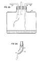
- an aseptic break in the system is desirable.
- Line 41 ends in a capillary tip 42 .
- This tip 42 is enclosed by teflon tubing 43 which curves to one side.
- the liquid flow is regulated so that separate droplets 44 are released from the capillary tip 42 , fall to the wall of the teflon tubing 43 , roll down its side to the end and drip into the bottle. Since teflon does not wet, the droplets roll separately down the side of the tubing and a bacterial contamination cannot be passed up the tube, even if it should reach the end of the teflon tube through splashing of the drops into the bottle.
- air from air source at vent 47 , which is sterilized by passing it through a 0.2 ⁇ m hydrophobic filter 46 , is used to pressurize the bottle 40 sufficiently to keep the liquid surface at a low level.
- the exit tube 48 begins at the bottom of the bottle 40 and passes out the stopper 49 . Liquid is forced out through the exit tube 48 by the increase in pressure initially imposed from the air source 47 and thereafter, with valve 45 closed, by the increase created by the incoming volume of the liquid.
- two of these aseptic break units are used in series.
- the desired gas mixture for aeration of bioreactor core 23 comes from a sterile gas supply (not shown) and passes through bioreactor core 23 via inlet 24 and, outlet 25 .
- the bioreactor is seeded with cells suspended in nutrient medium via inlet 21 , as described infra .
- nutrient medium must be added to and bled from the system. It is generally preferred to add nutrient make up, from a reservoir, not shown, through aseptic breaks 19 and 20 , via line 26 by operation of feed pump 36 .
- the bleeding process accomplishes the functions of maintaining bioreactor medium volume, harvesting products, and removing wastes. If the nutrient medium is inexpensive or all components are depleted simultaneously, it can merely be bled off to a reservoir in a cold room for concentration and purification of product. However, if the nutrient medium contains some expensive components, as is normally the case, a system can be employed to conserve and recirculate these expensive ingredients in particular.
- One such system is a tangential flow ultrafiltration module 16 with a 5-100K molecular weight cutoff, preferably as large as possible while still retaining product and growth factors.
- the nutrient medium feed line 17 enters the ultrafiltration module 16 and the medium flows tangentially across the membrane, out the exit port, and back into the bioreactor circulation.
- water and small molecular and ionic components of the nutrient medium flow through the ultrafiltration membrane are removed via permeate removal line 50 and are pumped away via valve 52 , pump 35 , valve 53 , and via line 55 , through aseptic breaks 56 , and 57 , to waste 59 via discharge line 58 .
- Proteins in the nutrient medium such as serum albumin, growth factors, and antibodies cannot pass through the ultrafiltration membrane and so remain in circulation. Under this condition, nutrient medium components which would be concentrated by continuous addition, i.e. those with a molecular weight greater than the effective membrane cutoff, are no longer added to the incoming nutrient medium. These components are simply allowed to circulate until their effectiveness wanes. Secreted cellular protein products, such as antibodies, continuously accumulate. Most cellular waste products are filtered out by the ultrafiltration module.
- the exit line 51 and the permeate line 50 from the ultrafiltration module 16 are connected by a valve 52 .
- the valve 52 is opened to line 51 , thus bypassing the operation of ultrafilter 16 while valve 53 is opened to line 54 and closed to line 53 and the nutrient medium containing the cellular products is pumped through line 54 into the product concentration circuit.
- the valve 36 is closed so the ultrafiltration module 37 is again working and appropriate amounts of expensive fetal calf serum, fresh growth factors, other hormones, etc. are again added to the incoming nutrient medium.
- the diverted nutrient medium, containing products can then be treated to concentrate the high molecular weight products, and separate them from the low molecular weight wastes, by the following procedure:
- the low molecular weight permeate is removed from the system, via line 64 , aseptic breaks 65 , 66 and then to waste 59 .
- the remaining stream of partially concentrated high molecular weight materials is provided with a surge buffer via line 61 to surge tank 62 , where the stream is reinjected by pump 63 into line 54 .
- the exit line from the first ultrafilter 60 is pumped, by pump 67 , via line 68 , to a second ultrafilter 70 .
- the permeate from the second ultrafilter 70 passes via line 71 through aseptic breaks 65 , 66 , to waste 59 .
- the product exiting ultrafilter 70 via line 72 , is provided with a second surge line 73 , provided with surge tank 74 , where the excess volume is recirculated via pump 75 to line 68 .
- the concentrate in line 72 is pumped by pump 76 through aseptic breaks 77 , 78 to concentrate collector vessel 80 .
- the components of the process stream are concentrated from their initial concentration in the process stream to about 100 times the initial levels, while the low molecular weight components are substantially completely removed by the ultrafiltration operations.
- the product will be mixed with the remaining increments of high molecular weight constituents of the nutrient, and will require additional isolation and purification to recover the product in purified form.
- Such operations are well known to those of ordinary skill in the art, and any known procedure appropriate to the specific product can be employed.
- the nutrient feed may be intermittant or continuous. Continuous operation is generally preferred to minimize the shock to the cells of the additions of large amounts of unconditioned nutrient in surges.
- the bleeding operation may be intermittant, or continuous, and may involve the part-time employment of the ultrafilter 16 , alternated with the by-passing of this fractional bleeding operation in favor of removal of an increment of the total stream for product recovery.
- the present invention includes four embodiments shown schematically in Figures 3, 4, 5, and 6, which allow for the incorporation of an oxygen exchange system, separate from the nutrient medium, into the bioreactor core composed of microporous and/or ultrafiltration membranes.
- the concept behind the use of the direct, compartmentalized gas exchange chamber is that a moderate, low pressure flow of air or other oxygen-rich gas mixture will provide maximal oxygenation of the cells, while permitting a much slower flow of nutrient medium.
- the result is the efficient and economical use of the expensive nutrient medium, an overall reduction in bioreactor size, reduced medium flow rates, and greater ease in maintaining sterility.
- These gas exchange compartment designs can be incorporated into either a stack arrangement or a spiral-wound membrane arrangement.
- Hybridoma cell lines vary greatly in their rates of monoclonal antibody production. Based on current knowledge, however, it may be estimated that a bioreactor that produces 1.0 g of antibody per day will need to contain about 1011 cells. Under traditional culture conditions, with glucose as the sole energy source, hybridoma cells will convert about one half of this glucose into lactate, a process that requires no oxygen. Many attempts have been made to minimize this anaerobic metabolic pathway in hybridoma cells, success at which increases cellular oxygen requirements.
- cultured hybridoma cells consume about 2.5 picomoles (pmol) of glucose per cell per day. Using this value, 1011 cells would consume 250 millimoles (mmol) of glucose per day. If only one half is metabolized aerobically, which requires six molecules of oxygen per molecule of glucose, then the oxygen requirement for 1011 cells is 1500 mmol of oxygen per day.
- the concentration of dissolved oxygen at 37°C is about 0.2 millimolar (mM) .
- the biochemistry of oxygen binding in cultured cells dictates that only about 50% of the dissolved oxygen is available for use. This means that the oxygen concentration of media at 37°C is effectively only 0.1 mM. At this concentration 15,000 liters of media would need to circulate daily to meet the oxygen requirements of a 1.0 g antibody per day bioreactor. This dictates a flow rate of 10 liters/min. to support 1011 cells.
- Glucose supplied at a concentration of 20 mM in nutrient medium is fully adequate to meet cellular needs. Assuming that the glucose is depleted 50% by the cells, its effective concentration is 10 mM. In the previous calculation it was estimated that 1011 cells would require 250 mmol of glucose per day (the entire aerobic and anaerobic requirement must be considered here). At an effective concentration of 10 mM glucose, 25 liters of nutrient medium would need to circulate per day or 0.02 liter/min.
- a bioreactor designed with compartmentalized gas exchange chambers can thus be expected to give an advantage of more than two orders of magnitude reduction in nutrient medium flow rates over dissolved gas bioreactors.
- the economic value of incorporating a separate air chamber into bioreactor design is obvious. Structurally there are several options available.
- the first of the four embodiments illustrated in Figure 3 is a multiple layer stacked membrane design.
- the basic bioreactor core consists of a multilayered series of alternating cell chambers, nutrient medium flow chambers, and gas exchange chambers.
- the gas exchange chambers are interleaved between two cell chambers, while the nutrient medium flow chambers are located as shown in Figure 3 .
- Air or another appropriate gas mixture would be passed directly through the inter-membrane space of the gas exchange chambers.
- the membranes which form the boundaries between cell chambers and gas exchange chambers would have to be ultraporous, hydrophobic membranes. This type of membrane would not allow the nutrient medium to pass through, but would allow excellent diffusion of oxygen to the cells and diffusion of CO2 away from the cells.
- the membranes which form the boundaries between cell chambers and nutrient medium flow chambers are microporous, hydrophilic membranes, normally separated by spacer screens.
- This simplest bioreactor core with an internal gas exchange chamber would therefore be constructed, as shown in Figure 3 , by layering materials in the following sequence: hydrophilic membrane 2 , spacer screen 4 , hydrophilic membrane 2 , spacer screen 4 , hydrophobic membrane 5 , spacer screen 4 , hydrophobic membrane 5 , spacer screen 4 .
- This sequence is repeated until the desired number of layers is achieved.
- the result is to create chambers in the following order through the bioreactor core: nutrient medium 3 , cell 1 , gas 6 , cell 1 , nutrient medium 3 , cell 1 , gas 6 , cell 1 , nutrient medium 3 , and so forth.
- each cell space 1 will receive nutrients and discharge products and soluble wastes from one side ( 3 ), while receiving oxygen and discharging carbon dioxide from the other side ( 6 ).
- Each nutrient medium flow chamber 3 and each gas exchange chamber 6 would supply two cell chambers 1 .
- FIG. 4 A variation of this simplest embodiment of the bioreactor core is shown in Figure 4 .
- This second embodiment retains the same membrane and chamber organization as in the first embodiment, but makes a modification in the cell chamber spacer screen to enhance gas exchange.
- This second embodiment results in the replacement of the solid fiber spacer screen with a screen composed of ultraporous, hydrophobic hollow fibers, sealed at the ends.
- the bioreactor core is constructed by layering materials in the following sequence: hydrophilic membrane 2 , solid fiber spacer screen 4 , hydrophilic membrane 2 , hollow fiber spacer screen 7 , hydrophobic membrane 5 , solid fiber spacer screen 4 , hydrophobic membrane 5 , solid fiber spacer screen 4 . This sequence is repeated until the desired number of layers is achieved.
- the surface area available for gas exchange through the hydrophobic membrane sheet in both the first embodiment and the second embodiment would be identical, in the second embodiment, the surface area for gas exchange would be increased over that in the first embodiment by the surface area of the spacer screen.
- This variation on the gas exchange chamber design therefore greatly increases the surface area for gas exchange, and adds the increased gas exchange area within the depth of the cell reaction zone, with the result that wider cell chambers can be used. Wider cell chambers hold more cells and thus reduce the size of the bioreactor, since additional layers of nutrient medium and gas exchange chambers are not necessary to support the additional cells.
- FIG. 5 Another variation of the simplest embodiment of the bioreactor core is shown in Figure 5 .
- This third embodiment retains the same membrane and chamber organization as in the first embodiment, but makes a modification in the cell chamber spacer screen to enhance cell attachment.
- This third embodiment results in the supplementation or replacement of the solid fiber spacer screen with suitable particulate support material for attachment dependent cells.
- the bioreactor core is constructed by layering materials in the following sequence: hydrophilic membrane 2 , solid fiber spacer screen 4 , hydrophilic membrane 2 , particulate support material 7 , with or without a spacer screen, hydrophobic membrane 5 , solid fiber spacer screen 4 . This sequence is repeated until the desired number of layers is achieved.
- the result is to create chambers in the following order through the bioreactor core: nutrient medium 3 , cell 1 , gas 6 , cell 1 , nutrient medium 3 , cell 1 , gas 6 , cell 1 , nutrient medium 3 , and so forth.
- the particulate support material 7 would still provide proper spacing of the membranes through the use of appropriate amounts of material, and also greatly increase the surface area for cell attachment. This second function is especially useful for culturing attachment dependent cells by providing surface area to which the cells may attach.
- FIG. 6 Another embodiment of the gas exchange chamber design is considerably different from the first three embodiments.
- This fourth design utilizes alternate cell and nutrient medium chambers separated by hydrophilic membranes, as shown in Figure 6 .
- the cell chamber spacer screen found in the simplest embodiment, is replaced by a layer of hydrophobic hollow fibers 5 , which can be cross laid with closed ended hollow fibers.
- the bioreactor core is constructed by layering materials in the following sequence: hydrophilic membrane 2 , spacer screen 4 , hydrophilic membrane 2 , hollow fibers 5 , hydrophilic membrane 2 , spacer screen 4 , hydrophilic membrane 2 , hollow fibers 5 . This sequence is repeated until the desired number of layers is achieved.
- the result is to create chambers in the following order through the bioreactor core: nutrient medium 3 , cell 1 , nutrient medium 3 , cell 1 , and so forth.
- the hollow fibers 5 maintain cell chamber 1 spacing, but extend from both sides of the membrane stack where they are gathered into a manifold (not shown in Figure 6 ). Air or the desired gas mixture is then pumped through the lumina of the hollow fibers and gas exchange can occur over the entire surface area of the fibers. While this arrangement is highly effective in operation, the difficulties of manifolding the hollow fiber membranes are considerable, and this embodiment is generally less preferred for that reason.
- All four of these compartmentalized gas exchange chamber embodiments provide for a much more rapid delivery of oxygen and removal of excess carbon dioxide than do designs where gases must travel dissolved in the nutrient medium.
- the nutrient medium may also be pumped at a much reduced rate which reflects the nutrient needs of the cells rather than their oxygen needs.
- Any of these four embodiments described herein may be incorporated into either of two bioreactor core configurations, namely a stack arrangement or a spiral wound arrangement.
- the first arrangement of the elements of the bioreactor is referred to herein as the stack.
- This particular approach utilizes layers of the appropriate membranes, each separated from its adjacent neighbors by a separator, which are sealed in the appropriate arrangements to constitute the various zones and chambers of the reactor.
- the stack is confined and contained within a reactor vessel or container (for convenience referred to as the "cube", although it should be understood that the shape can be any tetragon, and need not be a cube per se ) which is configured to receive the stack and provide manifolding for the supply to the various reactor chambers their respective input and to collect and provide for removal of the outputs.
- the manifolds are disposed in the following fashion: the seeding ports are preferably disposed along the four opposed edges of the cube normal to the plane in which the membrane sheets lie. Two opposed faces of the cube parallel to the membranes are not employed as manifolds. Of the remaining faces, each opposed pair serves as a bound of a manifold volume for a flow stream, either nutrient or oxygen. On one face, the medium is input to the reactor, while on the opposing face, the output of that stream from the reactor is withdrawn.
- each chamber is open to a manifold. This objective is conveniently achieved by sealing two opposite sides of each chamber, leaving the other edges open to the manifold in the cube appropriate for that chamber.
- Each cell chamber is ported into the corner seeding manifold, each air chamber is ported into the air manifold, and the nutrient chambers are ported into the nutrient manifold.
- the corners of the membranes are sealed into the corners of the cube.
- the boundaries between the seeding and air manifolds are sealed to the corresponding sides of the cube.
- the various seals preclude the various manifolds and the various chambers from communicating with those of different kinds.
- Each manifold is ported to the appropriate input or output lines of the system, as illustrated in Figure 1 .
- the stack is made up, and then placed into the cube, and then is sealed in place, and is ready for use.
- the running length is then cut transversely across the face of the "sandwich” at appropriate intervals to correspond to the dimensions required of the stack, yielding a flat "tubular” construct of dimensions appropriate to fit into the cube, and having open ends.
- the interior of each of these elements will constitute a medium chamber when the stack is fully assembled and installed in the cube for operation.
- a hydrophobic membrane, the dacron separator, and a second hydrophobic membrane are stacked with the separator in the center, and sealed by an adhesive along the edges.
- the running length is then cut transversely across the face of the "sandwich” at appropriate intervals to correspond to the dimensions required of the stack, yielding a flat "tubular" construct of dimensions appropriate to fit into the cube, and having open ends.
- the interior of each of these elements will constitute a gas chamber when the stack is fully assembled and installed in the cube for operation.
- the nutrient chambers are interleaved with the air chambers, with the hollow fiber membrane spacer elements disposed therebetween, with the open ends of all the nutrient chambers aligned with one another, and disposed at ninety degrees of the open ends of the alternating air chambers, which are thus all aligned.
- an appropriate adhesive is applied in excess at the corners, leaving all medium and gas ports open, such that seeding ports can be created by notching the glued areas to a sufficient depth so as to leave at each corner an opening suitable to communicate with the seeding port of the cube.
- This process forms the cell chambers which will constitute the cell reactor zones of the reactor. This procedure is continued until the appropriate number of chambers has been formed.
- Manifolding of the open flow chambers between the membranes is accomplished by placing the stack into the tetragonal box or cube made of inert material and slightly oversized to accommodate the stack loosely on the four sides facing the edges of the membranes, and thus forming manifolds on each side face of the cube.
- the membrane stack is held in place and the contents of the two sets of chambers are prevented from mixing by sealing with an adhesive material at each manifold boundary and along each top and bottom edge. Ports supply access to each of the four sides of the stack.
- the open ends of one set of the chambers are joined by one opposed pair of the manifolds and the open ends of the other, alternating, chambers are joined by the other manifold pair.
- Two different materials such as nutrient medium and oxygen stream, can then be passed through the appropriate alternating layers of the stack of membranes.
- the flow of the two different materials will be at right angles to each other, from the inlet port and manifold, through the chamber, and out the outlet manifold and port.
- a separate gas exchange chamber is preferably incorporated within the bioreactor core thereby eliminating the need for using the nutrient medium as a gas transport system.
- the problem with interleaving a separate gas exchange chamber in this bioreactor core structure, as shown in Figures 3, 4, and 5 is that all four side faces of the cube, and the four sides of the membrane stack require utilization for three flow streams, with only two axes of flow available.
- One solution to this problem is to seal the gas exchange chamber membranes along all four sides, except at two or four corners. Manifolds attached to the corners then allow for input and output of one of the flow streams, preferably the cell seeding stream.
- This arrangement allows one dimension of the membrane layer, and one pair of opposed manifolds, to be used for nutrient medium flow, the other dimension, and the other pair of manifolds, at a right angle to the first, to be used for air flow, and the corners to be used for the initial cell seeding. Since the seeding operation is generally of concern only "during reactor start-up, and then ordinarily employs very gentle flow rates and limited volumes, this approach results in preserving the large stack face manifolds for the continuing operations for uniform nutrient and oxygen supply.
- square hydrophilic and hydrophobic membranes can be arranged as shown in Figures 3, 4, or 5 with either solid fiber or hollow fiber spacer screens, and optionally particulate material, in the cell chambers as described previously in the first three embodiments of the gas exchange chamber.
- the membranes in this stack of membranes and spacer screens are sealed as shown in Figure 7 .
- the two hydrophilic membranes enclosing the nutrient medium chamber 2 are sealed all the way across one side and also on the opposing side.
- the hydrophobic and hydrophilic membranes enclosing the cell chamber 1 are sealed along all sides except for a small section 5 at the corners on the sides of the nutrient medium chamber seals.
- the hydrophobic and hydrophilic membranes enclosing the gas exchange chamber 4 are sealed along the entire side of the nutrient medium chamber openings and up to the cell chamber openings 5 along the sides of the nutrient medium chamber seals.
- Manifolding of the open flow chambers between the membranes is accomplished by placing the stack into a tetragonal box or cube made of inert material and slightly oversized to accommodate the stack loosely on the four sides as shown in Figure 8 .
- the membrane stack 5 is held in place and the contents of the three sets of chambers are prevented from mixing by sealing in two places along each edge 15 forming the manifolds 6 , 7 , and 8 , along the bottom, and against the lid which caps the unit.
- Ports 9 , 10, 11, 12, 13 and 14 supply access to each of the four sides and to four of the corners of the stack. All of the cell chamber openings are joined by corner manifolds 6 .
- Manifolds 8 on two opposing sides join the gas exchange chambers while manifolds 7 on the other two opposing sides distribute and collect the nutrient medium flow.
- cells can be seeded into the cell chambers, via input ports 13 , cell chamber manifold 6 , the cell chambers in the membrane stack 5 , cell chamber manifold 6 , and output ports 14 , while nutrient medium can be passed through spaces at a right angle to the direction of the seeding flow, via input port 11 , nutrient medium chamber manifold 7 , the nutrient medium chambers in the membrane stack 5 , nutrient medium chamber manifold 7 , and output port 12 .
- the cell spaces are closed off, while nutrient medium continuously perfuses the cells through the adjacent nutrient medium flow chambers and oxygen and carbon dioxide diffuse from and to the adjacent gas exchange chambers.
- the hollow fiber membranes carry the flow of the oxygen source into the cell chamber, and the hollow fibers must be directly manifolded to an air or oxygen supply.
- the hollow fibers must have open ends, which pass through the glue lines which close off the edges of the cell chamber to an air or oxygen manifold. Because of the difficulty of forming such an arrangement, this embodiment is not preferred.
- the second arrangement for the bioreactor core organizes the membranes and chamber layers in exactly the same relative configuration, but in a different physical arrangement. Rather than the stacks of membranes of the stack arrangement, in this arrangement the layers of membranes are wound into a spiral. This can be accomplished in either of two manners: 1) the end-wound spiral as shown in Figure 9 and 9a ; or 2) the center-wound spiral, starting the spiral in the middle of the membrane length, with the result that both ends are on the outer perimeter as shown in Figure 10 and 10a . Any of the three compartmentalized gas exchange chamber embodiments can be organized into a spiral, wound in either manner as can the simplest embodiment of the present invention.
- the end-wound spiral is begun by sealing each chamber into a central manifold.
- the membranes are then wound around this manifold center until the desired size is achieved, whereupon the outer manifold is sealed into place.
- the membrane layers form a nutrient medium chamber 106 , a cell chamber 104 , a gas exchange chamber 105 , and another cell chamber 104 .
- the cell chambers 104 are sealed into cell chamber manifolds 102 and the gas exchange chamber 105 is sealed into gas exchange chamber manifolds 103 .
- the gas exchange chamber is of course formed of hydrophobic membranes 108 while the cell chambers and the nutrient medium chamber are formed of hydrophilic membranes 107 .
- the entire spiral is then placed into a container whose outer shell 101 is shown in Figure 9 .
- the center-wound spiral is shown in Figure 10 and 10a and employs a generally double tear drop-shaped spindle 209 about which the membrane layers are wound.
- a generally double tear drop-shaped spindle 209 about which the membrane layers are wound.
- manifolds namely cell chamber manifolds 202 , and gas exchange chamber inlet and outlet manifolds 203 .
- the membranes are stacked prior to winding around spindle 209 so that the cell chamber 204 is sandwiched between gas exchange chamber 205 and nutrient medium chamber 206 .
- the entire spiral is then placed into a container whose outer shell 201 is shown in Figure 10 and 10a .
- the spiral-wound constructions shown in Figures 9 and 10 have a number of common elements. In each only one repeating unit of membranes is ordinarily used. Each membrane and spacer layer, solid or hollow fiber, is in the form of long strips of the desired width. Where appropriate the layers are sealed along the edges at the point at which the spiral will begin to be wound. Then the edges are sealed , preferably as the layers are wound into a spiral to compensate for the continuing change in spiral circumference which varies independently for each layer. The outer membrane of the first layer becomes the inner membrane of the next layer and so forth until the desired bioreactor diameter is achieved. Cell and gas exchange chambers are continuous along the spiral from the outside to the inside in the end-wound construction shown in Figure 9 and 9a and from the outside to the inside and back out in the center-wound construction shown in Figure 10 and 10a .
- the whole cylinder is slid into a surrounding shell (designated as 101 and 201 in Figures 9 , and 10 ) and sealed in place. The ends are then capped, leaving ports for nutrient medium to flow in or out.
- center wound spiral and end wound spiral configurations differ from the center wound spiral and end wound spiral configurations, as clearly shown in Figure 10 and 10a .
- the center wound spiral embodiment requires a central spindle, 209, rather than a manifold at the center. All the terminal manifolds are disposed around the outer periphery of the spiral winding, ported through the end cap of the shell structure.
- spiral wound reactor in its cartridge housing can be sealed in sterile condition, stored before use, and easily installed in about the same fashion as employed for handling of cartridge filters. With appropriate adjustments and modifications, the reactor can be used by installation in filter cartridge housings, making the set-up and instllation of the system, as well as its use, a conventient and familiar task for many plant personnel.
- Spirals can currently be constructed with a diameter of up to about 12 inches and a cylinder length of up to about 3 feet. Such a cylinder would have a total volume of about 21.2 liters which would mean a cell chamber capacity of about 5000 cm3. Correcting for the volume occupied by the spacer screen, the cell space is about 3000 cm3. At 5x10⁸ cells/cm3, such a reactor would contain about 1.5x10¹² cells and produce about 10 g of antibody per day. This is comparable to the production of a 1000 liter batch-type reactor. Many of these spiral units can be employed in parallel to construct a bioreactor of any desired capacity.
- this invention relates to layered membrane immobilized cell bioreactors and various designs for compartmentalized gas exchange chambers as applicable to layered membrane immobilized cell bioreactors.
- the incorporation of compartmentalized gas exchange chambers into a bioreactor provides maximal oxygenation, of the cells for greater production of antibodies, while allowing for minimal circulation of nutrient medium for greater efficiency and compactness of design. Economic advantages accrue from the greater metabolic activity of the cells which can manufacture more of the desired products and the reduction in nutrient medium pumping requirements.
- the process of colonizing the bioreactor can be accomplished by growing a sufficient number of cells in a traditional tissue culture facility and transferring them to the bioreactor.
- this approach requires that large quantities of sterile media be handled and that considerable incubator space be available to grow the cells. This is a very time consuming and expensive means toward bioreactor start up.
- a more practical approach is to grow a relatively small number of cells with which to seed the bioreactor. Once colonized, the bioreactor is filled to capacity by the subsequent divisions of the cells. Relatively uniform packing of the cells is essential for maximum bioreactor efficiency and productivity.
- the bioreactor designs of the present invention will result in cell seeding which distributes the cells uniformly within the cell chambers using a self regulatory process.
- the microporous membranes of the bioreactor designs of the present invention allow the nutrient medium to pass through while retaining the cells.
- the two membranes which form the cell chamber are kept uniformly separated by a spacer screen.
- the pressure forces the media portion through the microporous membrane into the nutrient medium flow chamber.
- the cells cannot pass through the membrane so are filtered out of the seed culture medium and thus deposited immediately in front of the seeding entry port. These cells reduce medium flow through the membrane in that area. Seed culture now entering the cell chamber passes over the deposited cells to open membrane where the medium can pass through, again filtering out the suspended cells. Cells are thus continuously deposited at the periphery of the ever-expanding monolayer until the membrane is covered.
- the nutrient medium circulation system must begin to operate to provide nutrients and oxygen for the cells.
- the nutrients diffuse from the nutrient medium chamber into the cell chamber.
- the cells then reproduce to substantially fill the reactor zone, with a high population density and thus with high production capacity.
- the membranes employed will generally be selected from among those commercially available to the art.
- a wide variety of both ultraporous, hydrophobic membranes suitable for the gas transfer, and microporous, hydrophilic membranes suitable for the nutrient diffusion, are available from a number of sources.
- Spacer screens to be employed in the present invention are generally familiar to the art, and are commercially available in a variety of materials, specific configurations, and dimensions. Conveniently, woven dacron polyester materials of appropriate dimensions may be employed. When it is desired to employ hollow ultraporous membrane hollow fiber spacers, these materials are also available from a number of sources.
- Particulate materials suited for use in the cell reactor with attachment dependent cells are also widely known to the art and are generally available.
- Nutrients suitable for the cultivation of cells, particularly hybridoma cells, in the context of the present invention are well known. Any nutrient suited for a particular cell line can be employed.
Landscapes
- Health & Medical Sciences (AREA)
- Organic Chemistry (AREA)
- Life Sciences & Earth Sciences (AREA)
- Engineering & Computer Science (AREA)
- Bioinformatics & Cheminformatics (AREA)
- Chemical & Material Sciences (AREA)
- Zoology (AREA)
- Wood Science & Technology (AREA)
- Sustainable Development (AREA)
- Microbiology (AREA)
- Biotechnology (AREA)
- Biomedical Technology (AREA)
- Biochemistry (AREA)
- General Engineering & Computer Science (AREA)
- General Health & Medical Sciences (AREA)
- Genetics & Genomics (AREA)
- Clinical Laboratory Science (AREA)
- Apparatus Associated With Microorganisms And Enzymes (AREA)
Claims (8)
- Verfahren für die Kultivierung von Hybridoma-Zellen und für die Herstellung und das Gewinnen (recovery) exozellulärer Produkte daraus,
unter Verwendung eines Reaktors für die Kultivierung von Zellen und die Produktion und das Gewinnen von exozellulären Produkten daraus,
wobei der Kern des Reaktors (core of reactor) eine hydrophobe, mikroporöse membranbegrenzte Luftkammer aufweist, die - als Schicht - zwischen zwei Zellkammern angeordnet ist, die begrenzt sind von mikroporösen, hydrophilen Membranen, die auch eine Kammer begrenzen, die so angepaßt ist, das sie zirkulierendes Nährmedium enthält, wobei das Verfahren aufweist:
das Aussähen von Hybridomen in das Zellkompartiment, das Zuführen von notwendigen Nährstoffen und von Sauerstoff von den nebenliegenden Nährstoff- und Gaskompartimenten, um die Replikation der Hybridomen bis zu einer hohen Zelldichte in dem Zellkompartiment zu ermöglichen und das Gewinnen der exozellulären Produkte aus der Flüssigkeit, welche das Nährstoffkompartiment verläßt, in welches die Produkte über die mikroporöse Membran eindiffundiert sind. - Reaktor für immobilisierte Zellen zur Verwendung im Verfahren von Anspruch 1, wobei der Reaktor voneinander beabstandete, flexible Membranen aufweist, die geschlossen (sealed) sind und so geformt (manifolded) sind, daß sie zumindest ein Zellkompartiment zum Umschließen lebender Zellen für die Sekretion exozellulärer Produkte, ein Nährstoffkompartiment (nutrient compartment) zum Zuführen von Flüssig-Nährstoffen in das Zellkompartiment und zum Abtrennen (removal) der exozellulären Produkte daraus und ein Gaskompartiment zum Versorgen des Zellkompartimentes mit einem freien Sauerstoff aufweisenden Gas,
dadurch gekennzeichnet,(a) daß jedes Zellkompartiment an ein Gaskompartiment und ein Nährstoffkompartiment grenzt und nur von dem nächsten Zellkompartiment durch ein Kompartiment getrennt ist;(b) daß das Gaskompartiment von den inneren Oberflächen von zwei hydrophoben Membranen gebildet wird, jedes Zellkompartiment von der äußeren Oberfläche einer hydrophoben Membran und der inneren Oberfläche einer mikroporösen hydrophilen Membran gebildet wird, und die äußeren Oberflächen der mikroporösen hydrophilen Membranen jeweils eine Nährkompartiment-Oberfläche bilden;(c) daß Beabstandungsmittel (spacer means) die Membranen voneinander beabstanden, so daß die Zellen im Zellkompartiment innerhalb eines Sauerstoff-Diffusionsabstandes von nicht mehr als 200 µm zur hydrophoben Gaskompartiment-Membran angeordnet ist. - Reaktor nach Anspruch 2, bei dem die hydrophoben Membranen porös sind mit einer Porengröße zwischen 0.005 und 0.1 µm.
- Reaktor nach Anspruch 3, bei dem die hydrophoben Membranen eine Porengröße von zwischen 0.01 und 0.05 µm haben.
- Reaktor nach einem der Ansprüche 2 bis 4, bei dem das Beabstandungsmittel eine Mehrzahl von porösen Hohlfasermembranen aufweist.
- Reaktor nach einem der Ansprüche 2 bis 5, bei dem alle Kompartimente in voneinander beabstandeter Relation durch Beabstandungsmittel gehalten werden.
- Reaktor nach einem der Ansprüche 2 bis 6, bei dem die Kompartimente in einer spiralgewundenen Konfiguration angeordnet sind.
- Reaktor nach einem der Ansprüche 2 bis 7, der so konfiguriert ist, daß die Zellen innerhalb eines Abstandes von 100 bis 200 µm des hydrophoben Gaskompartiment-Membrane angeordnet sind.
Priority Applications (1)
| Application Number | Priority Date | Filing Date | Title |
|---|---|---|---|
| AT88906492T ATE95561T1 (de) | 1987-06-30 | 1988-06-28 | Zellzuchtreaktor mit drei kammern, die von hydrophoben und hydrophilen membranen begrenzt sind. |
Applications Claiming Priority (2)
| Application Number | Priority Date | Filing Date | Title |
|---|---|---|---|
| US6820387A | 1987-06-30 | 1987-06-30 | |
| US68203 | 1987-06-30 |
Publications (2)
| Publication Number | Publication Date |
|---|---|
| EP0360837A1 EP0360837A1 (de) | 1990-04-04 |
| EP0360837B1 true EP0360837B1 (de) | 1993-10-06 |
Family
ID=22081072
Family Applications (1)
| Application Number | Title | Priority Date | Filing Date |
|---|---|---|---|
| EP88906492A Expired - Lifetime EP0360837B1 (de) | 1987-06-30 | 1988-06-28 | Zellzuchtreaktor mit drei kammern, die von hydrophoben und hydrophilen membranen begrenzt sind |
Country Status (4)
| Country | Link |
|---|---|
| EP (1) | EP0360837B1 (de) |
| JP (1) | JPH0763354B2 (de) |
| DE (1) | DE3884801D1 (de) |
| WO (1) | WO1989000188A1 (de) |
Families Citing this family (19)
| Publication number | Priority date | Publication date | Assignee | Title |
|---|---|---|---|---|
| KR0131822B1 (ko) * | 1988-05-23 | 1998-04-11 | 죤 에프. 튜은트 | 바이오 반응기 장치 |
| US5605835A (en) * | 1988-05-23 | 1997-02-25 | Regents Of The University Of Minnesota | Bioreactor device with application as a bioartificial liver |
| US5079168A (en) * | 1988-08-10 | 1992-01-07 | Endotronics, Inc. | Cell culture apparatus |
| JPH0292270A (ja) * | 1988-09-30 | 1990-04-03 | Terumo Corp | 細胞培養装置 |
| CA2054210A1 (en) * | 1989-05-05 | 1990-11-06 | William R. Tolbert | Cell culture system |
| US5330915A (en) * | 1991-10-18 | 1994-07-19 | Endotronics, Inc. | Pressure control system for a bioreactor |
| DE19537774C2 (de) * | 1994-11-18 | 1996-09-19 | Heraeus Instr Gmbh | Verfahren zur Zellkultivierung und Vorrichtung zur Durchführung des Verfahrens |
| BE1009306A5 (fr) | 1995-04-28 | 1997-02-04 | Baxter Int | Bioreacteur. |
| US5728581A (en) * | 1995-06-07 | 1998-03-17 | Systemix, Inc. | Method of expanding hematopoietic stem cells, reagents and bioreactors for use therein |
| AU7172598A (en) * | 1997-05-07 | 1998-11-27 | Baxter International Inc. | Method and apparatus for high volume production of viral particles |
| US5955353A (en) * | 1997-05-22 | 1999-09-21 | Excorp Medical, Inc. | Hollow fiber bioreactor with an extrafilament flow plug |
| AU2005243606B2 (en) * | 2004-05-18 | 2009-06-25 | Biogill Environmental Pty Limited | Membrane bioreactor |
| CN1989236B (zh) | 2004-05-18 | 2012-05-16 | 澳大利亚核科学技术组织 | 膜生物反应器 |
| US7745209B2 (en) | 2005-07-26 | 2010-06-29 | Corning Incorporated | Multilayered cell culture apparatus |
| US7897048B2 (en) | 2005-11-17 | 2011-03-01 | Australian Nuclear Science And Technology Organisation | Membrane bioreactor and sewage treatment method |
| WO2008028241A1 (en) * | 2006-09-06 | 2008-03-13 | The University Of Queensland | Microbioreactor |
| CA2881647C (en) * | 2012-08-10 | 2015-09-22 | Paragonix Technologies, Inc. | System for hypothermic transport of samples |
| CN111630151A (zh) * | 2018-01-24 | 2020-09-04 | 宇部兴产株式会社 | 细胞培养模块 |
| CN118956551A (zh) * | 2024-07-23 | 2024-11-15 | 上海同腾生物科技有限公司 | 一种应用于固定床生物反应器的可回收细胞膜组件以及细胞扩增回收培养工艺 |
Family Cites Families (14)
| Publication number | Priority date | Publication date | Assignee | Title |
|---|---|---|---|---|
| US3821087A (en) * | 1972-05-18 | 1974-06-28 | Dedrick R | Cell culture on semi-permeable tubular membranes |
| US4201845A (en) * | 1976-04-12 | 1980-05-06 | Monsanto Company | Cell culture reactor |
| US4087327A (en) * | 1976-04-12 | 1978-05-02 | Monsanto Company | Mammalion cell culture process |
| DE2726313C3 (de) * | 1977-06-10 | 1980-02-07 | Battelle-Institut E.V., 6000 Frankfurt | Verfahren zur in-vitro-Biosynthese von Hormonen, insbesondere von Insulin |
| JPS5642584A (en) * | 1979-09-18 | 1981-04-20 | Asahi Chem Ind Co Ltd | Cell cultivation method |
| DE2940446C2 (de) * | 1979-10-05 | 1982-07-08 | B. Braun Melsungen Ag, 3508 Melsungen | Züchtung von tierischen Zellen in Suspensions- und Monolayerkulturen in Fermentationsgefäßen |
| DE3107874A1 (de) * | 1981-03-02 | 1982-09-16 | Akzo Gmbh, 5600 Wuppertal | Verfahren zur blasenfreien gaseinspeisung |
| US4537860A (en) * | 1982-12-08 | 1985-08-27 | Monsanto Company | Static cell culture maintenance system |
| US4661458A (en) * | 1983-08-31 | 1987-04-28 | Cell Environmental Systems, Ltd. | Cell culture system |
| JPS6178397A (ja) * | 1984-09-22 | 1986-04-21 | Kao Corp | 酵素及び微生物の反応方法 |
| US4748124A (en) * | 1984-10-30 | 1988-05-31 | E. I. Du Pont De Nemours And Company | Compartmentalized cell-culture device and method |
| EP0220650A3 (de) * | 1985-10-21 | 1988-08-24 | Endotronics Inc. | Verfahren und Vorrichtung zur Züchtung von Zellkulturen |
| US4720462A (en) * | 1985-11-05 | 1988-01-19 | Robert Rosenson | Culture system for the culture of solid tissue masses and method of using the same |
| US4661455A (en) * | 1986-01-16 | 1987-04-28 | Dorr-Oliver Incorporated | Membrane cell culturing device |
-
1988
- 1988-06-28 EP EP88906492A patent/EP0360837B1/de not_active Expired - Lifetime
- 1988-06-28 DE DE88906492T patent/DE3884801D1/de not_active Expired - Lifetime
- 1988-06-28 JP JP63505981A patent/JPH0763354B2/ja not_active Expired - Lifetime
- 1988-06-28 WO PCT/US1988/002209 patent/WO1989000188A1/en not_active Ceased
Non-Patent Citations (1)
| Title |
|---|
| Biotechnology and Bioengineering, vol. XXIII, p. 79-95 (1981) (K. KU et al) "Development of a Hollow-Fiber System for Large-Scale Culture of Mammalian Cells", s. pp. 83-94 * |
Also Published As
| Publication number | Publication date |
|---|---|
| JPH02501352A (ja) | 1990-05-17 |
| WO1989000188A1 (en) | 1989-01-12 |
| EP0360837A1 (de) | 1990-04-04 |
| DE3884801D1 (de) | 1993-11-11 |
| JPH0763354B2 (ja) | 1995-07-12 |
Similar Documents
| Publication | Publication Date | Title |
|---|---|---|
| US4937196A (en) | Membrane bioreactor system | |
| EP0360837B1 (de) | Zellzuchtreaktor mit drei kammern, die von hydrophoben und hydrophilen membranen begrenzt sind | |
| US4661458A (en) | Cell culture system | |
| EP2148922B1 (de) | Zellexpansionssystem und verfahren zu seiner verwendung | |
| EP0416061B1 (de) | Zellkultureinheit mit OXYGENATOR FÜR ZUCHTMEDIUM | |
| US6468792B1 (en) | Process and device for culturing and/or treating cells | |
| EP0419234A2 (de) | Vorrichtung für Zellkultur | |
| US5786215A (en) | Method for culturing animal cells | |
| US6228607B1 (en) | Bioreactor | |
| US8101387B2 (en) | Process to sequence bioreactor modules for serial gas flow and uniform gas velocity | |
| EP0269444B1 (de) | Vorrichtung und Verfahren zum Massentransfer von biologisch-pharmazeutischen Medien | |
| AU723592B2 (en) | Apparatus for the large scale growth and packaging of cell suspensions and three-dimensional tissue cultures | |
| US6214574B1 (en) | Cross-flow filtration and culture method | |
| AU778141B2 (en) | Method for cultivating cells, a membrane module, utilization of a membrane module and reaction system for cultivation of said cells | |
| AU611703B2 (en) | Cell growth reactor with three compartments formed by hydrophobic and hydrophilic membranes | |
| EP0153405B1 (de) | Zellkulturanlage | |
| JP2675408B2 (ja) | 中空糸膜型バイオリアクター | |
| US20240034967A1 (en) | Device for producing metabolites | |
| WO1988004318A1 (en) | Bioreactor and use thereof | |
| AU768658B2 (en) | Culture and device method |
Legal Events
| Date | Code | Title | Description |
|---|---|---|---|
| PUAI | Public reference made under article 153(3) epc to a published international application that has entered the european phase |
Free format text: ORIGINAL CODE: 0009012 |
|
| 17P | Request for examination filed |
Effective date: 19891229 |
|
| AK | Designated contracting states |
Kind code of ref document: A1 Designated state(s): AT BE CH DE FR GB IT LI LU NL SE |
|
| 17Q | First examination report despatched |
Effective date: 19920716 |
|
| GRAA | (expected) grant |
Free format text: ORIGINAL CODE: 0009210 |
|
| AK | Designated contracting states |
Kind code of ref document: B1 Designated state(s): AT BE CH DE FR GB IT LI LU NL SE |
|
| PG25 | Lapsed in a contracting state [announced via postgrant information from national office to epo] |
Ref country code: IT Free format text: LAPSE BECAUSE OF FAILURE TO SUBMIT A TRANSLATION OF THE DESCRIPTION OR TO PAY THE FEE WITHIN THE PRE;WARNING: LAPSES OF ITALIAN PATENTS WITH EFFECTIVE DATE BEFORE 2007 MAY HAVE OCCURRED AT ANY TIME BEFORE 2007. THE CORRECT EFFECTIVE DATE MAY BE DIFFERENT FROM THE ONE RECORDED.SCRIBED TIME-LIMIT Effective date: 19931006 Ref country code: NL Effective date: 19931006 Ref country code: FR Effective date: 19931006 Ref country code: LI Effective date: 19931006 Ref country code: DE Effective date: 19931006 Ref country code: AT Effective date: 19931006 Ref country code: SE Effective date: 19931006 Ref country code: BE Effective date: 19931006 Ref country code: CH Effective date: 19931006 |
|
| REF | Corresponds to: |
Ref document number: 95561 Country of ref document: AT Date of ref document: 19931015 Kind code of ref document: T |
|
| REF | Corresponds to: |
Ref document number: 3884801 Country of ref document: DE Date of ref document: 19931111 |
|
| REG | Reference to a national code |
Ref country code: CH Ref legal event code: PL |
|
| EN | Fr: translation not filed | ||
| NLV1 | Nl: lapsed or annulled due to failure to fulfill the requirements of art. 29p and 29m of the patents act | ||
| PG25 | Lapsed in a contracting state [announced via postgrant information from national office to epo] |
Ref country code: LU Free format text: LAPSE BECAUSE OF NON-PAYMENT OF DUE FEES Effective date: 19940630 |
|
| PLBE | No opposition filed within time limit |
Free format text: ORIGINAL CODE: 0009261 |
|
| STAA | Information on the status of an ep patent application or granted ep patent |
Free format text: STATUS: NO OPPOSITION FILED WITHIN TIME LIMIT |
|
| 26N | No opposition filed | ||
| PGFP | Annual fee paid to national office [announced via postgrant information from national office to epo] |
Ref country code: GB Payment date: 19950509 Year of fee payment: 8 |
|
| PG25 | Lapsed in a contracting state [announced via postgrant information from national office to epo] |
Ref country code: GB Effective date: 19960628 |
|
| GBPC | Gb: european patent ceased through non-payment of renewal fee |
Effective date: 19960628 |