EP0360033B1 - Cable traction device - Google Patents
Cable traction device Download PDFInfo
- Publication number
- EP0360033B1 EP0360033B1 EP89115800A EP89115800A EP0360033B1 EP 0360033 B1 EP0360033 B1 EP 0360033B1 EP 89115800 A EP89115800 A EP 89115800A EP 89115800 A EP89115800 A EP 89115800A EP 0360033 B1 EP0360033 B1 EP 0360033B1
- Authority
- EP
- European Patent Office
- Prior art keywords
- pressure
- chain
- rope
- rollers
- elements
- Prior art date
- Legal status (The legal status is an assumption and is not a legal conclusion. Google has not performed a legal analysis and makes no representation as to the accuracy of the status listed.)
- Expired - Lifetime
Links
- 238000005096 rolling process Methods 0.000 claims description 3
- 230000000284 resting effect Effects 0.000 claims 1
- 229910000831 Steel Inorganic materials 0.000 description 2
- 239000000835 fiber Substances 0.000 description 2
- 239000010959 steel Substances 0.000 description 2
- 238000005299 abrasion Methods 0.000 description 1
- 238000007792 addition Methods 0.000 description 1
- 238000010516 chain-walking reaction Methods 0.000 description 1
- 239000000428 dust Substances 0.000 description 1
- 230000002349 favourable effect Effects 0.000 description 1
- 239000012209 synthetic fiber Substances 0.000 description 1
- 229920002994 synthetic fiber Polymers 0.000 description 1
Images

Classifications
-
- B—PERFORMING OPERATIONS; TRANSPORTING
- B66—HOISTING; LIFTING; HAULING
- B66D—CAPSTANS; WINCHES; TACKLES, e.g. PULLEY BLOCKS; HOISTS
- B66D1/00—Rope, cable, or chain winding mechanisms; Capstans
- B66D1/60—Rope, cable, or chain winding mechanisms; Capstans adapted for special purposes
- B66D1/74—Capstans
- B66D1/7415—Friction drives, e.g. pulleys, having a cable winding angle of less than 360 degrees
Definitions
- the invention relates to a cable pull device with a driven traction sheave and with a continuous rope, the load strand wraps around the traction sheave and at the end of the wrapping of at least one pressure element via pressure elements which are arranged in the links of an endless chain rotating around a guide element, in the cable groove of the Traction sheave is pressed, wherein the guide element is designed as a pressure element and has at least one running surface parallel to the bottom of the cable groove, on which pressure rollers roll, which are rotatably mounted in the chain.
- a cable pulling device of this type is known (US-A-2 938 707), in which the cable with the pressure rollers is pressed into the cable groove of the traction sheave. Since the pressure rollers only have at most one line contact with the rope, they generate a high specific contact pressure on it, which plastically deforms the rope when large loads are to be lifted or lowered with the rope. In addition, the pressure rollers on the rope move in the longitudinal direction while they exert their contact pressure on the rope, whereby the crushing stress on the rope is further increased and this is subject to high wear.
- a cable pulling device is also known (DE-B-22 01 548), in which the pressure element is formed by three rollers mounted on a vibrating beam, which on the inside of the links, designed as a rolling surface, one around a guide ramp encircling, endless chain presses, the chain links press the rope into the rope groove of the traction sheave.
- the pins of the chain carry chain rollers on the outside of the chain links, which engage with notches in the drive pulley and ensure that the chain is carried along by the drive pulley and roll on the guide ramp.
- the noise caused by the chain running around the guide ramp is very large, since the tension of the chain is reduced when it is pressed onto the rope, and the movement play between the guide ramp and chain that is caused thereby leads to rattling.
- Another known embodiment of a rope drive uses an endless pressure chain with chain links which have pressure pieces which press the rope into the rope groove of the rope sheave (BE-A-827 486).
- the pressure is generated by means of three pressure rollers, which are arranged in a chain housing that can be positioned radially against the sheave.
- the chain is returned via two pulleys.
- each chain element designed as a pressure piece always executes a tilting movement as soon as it runs in or out under one of the pressure rollers. This does not result in a uniform, full-surface contact pressure, but in line contact between the chain link and rope, which results in uneven pressure and high rope wear.
- the object of the invention is to design a cable pulling device of the type explained in the introduction in such a way that a good frictional connection between the cable and the traction sheave is produced, which permits a high cable load without the high pressure of the pressing element required for this purpose plastically deforming the outer wires of the cable or Rattling noises are generated.
- This arrangement has the advantage that a statically acting, distributed over a relatively large surface pressure force acts on the rope, but the pressure pieces can not perform pivoting movements under contact pressure, since the contact pressure only occurs when the pressure piece is fully on the rope. Since the pressure surface remains constant, the permissible pressure on the rope edge fibers is not exceeded even under high loads. So that there is always optimal contact between the pressure pieces and the rope even with a non-uniform course of the rope, it is expedient to mount the pressure element in a tiltable manner.
- each pressure piece has at least two pressure rollers arranged at a distance from one another in the longitudinal direction of the chain.
- the pressure rollers are arranged in the longitudinal center plane of the pressure pieces. With particularly high contact forces or with the narrow width of the pressure pieces determined by the rope shape, it is possible to arrange the pressure rollers on both outer sides of the pressure pieces. For special applications it can be useful to combine the different pressure roller arrangements.
- the pressure rollers are designed as roller bearings with a reinforced outer ring, it is ensured that the high radial contact forces are reliably transmitted to the pressure pieces; The rolling elements are protected against abrasion and dust when installing closed bearings.
- the length of the running surface of the pressure element parallel to the base of the cable groove is at least as long as the distance which two pressure pieces in succession in the chain take up. The longer the parallel part of the tread, the more pressure pieces can transmit the contact pressure and the lower the surface pressure on the rope edge fibers.
- the chain can also be designed so that successive thrust pieces are connected to one another by link plates which are mounted on the bolts of the pressure rollers.
- 10 denotes a cable pulling device with a continuous pulling cable 11, which is preferably designed as a steel cable and on the load strand 12 of which the load to be moved hangs, whereas the lost drum 13 is loaded only by its own weight.
- the load strand 12 of the rope 11 runs tangentially into the rope groove 16 of a traction sheave 15 rotatably mounted in the housing 14, wraps around it and is again guided tangentially out of the housing 14 as a lost drum 13.
- the drive of the traction sheave 15 is not the subject of the invention and is therefore not shown.
- the traction sheave 15 has a semi-circular rope groove 16 adapted to the profile of the rope 11.
- the rope groove 16 can also be designed as a wedge groove, as is the case in FIG. 5 is shown.
- the rope 11 is pressed at the end of its looping path by a pressure device 17 into the rope groove 16 of the traction sheave 15.
- the pressure device 17 consists of a kidney-shaped pressure element 19 which is tiltably mounted on a spring-loaded lever 18 and on the running surface 20 of which pressure rollers 21 roll.
- the pressure rollers 21 are mounted on the pin 25 of an articulated chain 22, the chain links of which are alternately mounted on the pin 25 by pressure pieces 24 and on their outer sides 33 stored tabs 26 are formed.
- the running surface 20 of the pressure element 19 runs on its part facing the traction sheave 15 over the length L parallel to the cable groove 16 of the traction sheave 15 and is delimited on each side by a guide web 27 in order to prevent the chain 22 from slipping off the running surface 20 and to give the pressure rollers 21 lateral guidance.
- the pressure pieces 24 are circularly adapted on their side of the traction sheave 15 facing the cable 11 and, as shown in FIGS. 3 and 5, have a profiling 28 which is adapted to the outer diameter of the cable 11.
- This profile design has the advantage that the contact pressure is evenly distributed on the rope 11, which leads to a reduction in the wear of the rope 11.
- the pressure pieces 24 are provided on the side facing the pressure element 19 in the running direction of the chain 22 with a groove 29 and at the front and rear end with a transverse bore which serve to receive bolts 25 which are also axes of the pressure rollers 21.
- the pressure rollers 21 are designed as roller bearings with a reinforced outer ring in order to be able to transmit large pressure forces. Closed bearings are used to protect against foreign body entry.
- the pressure element 19 has a length L which is at least as long as the distance S which two pressure pieces 24 consecutive in the chain occupy.
- An embodiment is particularly expedient in which the length L of the running surface of the pressure element is three times as great as the distance S which two successive pressure pieces take up. The rope is then pressed into the groove over a large length. However, this embodiment is not shown in the drawing. Due to the geometric design of the pressure element 19, a pivoting movement of the pressure pieces 24 under the contact pressure is prevented and line contacts between pressure piece 24 and rope 11 are avoided, which result in high rope wear.
- FIG. 4 A further possible arrangement of the pressure rollers 21 on the pressure piece 24 is shown in FIG. 4.
- two pressure rollers 21 are overhung on the outside 33 of the pressure piece 24 on each pin 25, which roll on running surfaces 20 of the pressure element 19 and from one in the middle of the treads 20 arranged guide web 27 are guided. This reduces the surface pressure between the pin 25 and the pressure piece 24.
- the traction sheave 15 rotates, the rope 11 and the chain 22 are taken along by frictional engagement at the same angular velocity.
- the frictional engagement can be converted into frictional engagement if a type of sprocket with the pitch of the chain 22 is attached to the drive pulley 15. In this case, it is sufficient if a chain wheel is attached to only one side of the chain, in which the bolts 25 engage only at one end.
- the chain 22 itself is not subjected to any tensile load and therefore runs largely wear-free on the running surface 20 around the pressure element 19.
- the invention is not limited to the illustrated and described embodiment, but several changes and additions are possible without leaving the scope of the invention.
- a knitted synthetic fiber belt as a traction device, which has a large, load-distributing support on a flat, rubberized traction sheave and could use favorable coefficients of friction.
- the pressure pieces can also be provided with at least one pressure roller in the middle. It is only important that there is no pivoting movement of the pressure pieces under contact pressure.
- the pressure element 19 can also be adjusted depending on the load.
Description
Die Erfindung betrifft eine Seilzugvorrichtung mit einer angetriebenen Treibscheibe und mit einem durchlaufenden Seil, dessen Lasttrum die Treibscheibe umschlingt und am Ende der Umschlingung von mindestens einem Andruckelement über Druckelemente, die in den Gliedern einer um ein Führungselement umlaufenden endlosen Kette angeordnet sind, in die Seilrille der Treibscheibe gedrückt wird, wobei das Führungselement als Andruckelement ausgebildet ist und mindestens eine zum Seilrillengrund parallele Lauffläche aufweist, auf der sich Druckrollen abwälzen, die in der Kette drehbar gelagert sind.The invention relates to a cable pull device with a driven traction sheave and with a continuous rope, the load strand wraps around the traction sheave and at the end of the wrapping of at least one pressure element via pressure elements which are arranged in the links of an endless chain rotating around a guide element, in the cable groove of the Traction sheave is pressed, wherein the guide element is designed as a pressure element and has at least one running surface parallel to the bottom of the cable groove, on which pressure rollers roll, which are rotatably mounted in the chain.
Es ist eine Seilzugvorrichtung dieser Art bekannt (US-A-2 938 707), bei der das Seil mit den Druckrollen in die Seilrille der Treibscheibe gedrückt wird. Da die Druckrollen nur höchstens eine Linienberührung mit dem Seil haben, erzeugen sie auf diesem einen hohen spezifischen Anpreßdruck, der das Seil plastisch verformt, wenn mit dem Seil große lasten gehoben oder gesenkt werden sollen. Außerdem wandern die Druckrollen auf dem Seil in dessen Längsrichtung, während sie ihren Anpreßdruck auf das Seil ausüben, wodurch die Quetschbeanspruchung des Seiles noch weiter gesteigert wird und dieses einem hohen Verschleiß unterliegt.A cable pulling device of this type is known (US-A-2 938 707), in which the cable with the pressure rollers is pressed into the cable groove of the traction sheave. Since the pressure rollers only have at most one line contact with the rope, they generate a high specific contact pressure on it, which plastically deforms the rope when large loads are to be lifted or lowered with the rope. In addition, the pressure rollers on the rope move in the longitudinal direction while they exert their contact pressure on the rope, whereby the crushing stress on the rope is further increased and this is subject to high wear.
Es ist ferner eine Seilzugvorrichtung bekannt (DE-B-22 01 548), bei der das Andruckelement von drei auf einem Schwingbalken montierten Rollen gebildet wird, die auf die als Wälzfläche ausgeführte Innenseite der Glieder einer um eine Führungsrampe umlaufende, endlose Kette drückt, wobei die Kettenglieder das Seil in die Seilrille der Treibscheibe pressen. Die Bolzen der Kette tragen an den Außenseiten der Kettenglieder Kettenrollen, die mit Einkerbungen in der Treibscheibe in Eingriff sind und für die Mitnahme der Kette durch die Treibscheibe sorgen und auf der Führungsrampe abrollen.A cable pulling device is also known (DE-B-22 01 548), in which the pressure element is formed by three rollers mounted on a vibrating beam, which on the inside of the links, designed as a rolling surface, one around a guide ramp encircling, endless chain presses, the chain links press the rope into the rope groove of the traction sheave. The pins of the chain carry chain rollers on the outside of the chain links, which engage with notches in the drive pulley and ensure that the chain is carried along by the drive pulley and roll on the guide ramp.
Bei der beschriebenen Vorrichtung ist die Geräuschentwicklung durch das Umlaufen der Kette über die Führungsrampe sehr groß, da sich die Spannung der Kette beim Andruck auf das Seil verringert und das dadurch vorhandene Bewegungsspiel zwischen Führungsrampe und Kette zum Klappern führt.In the described device, the noise caused by the chain running around the guide ramp is very large, since the tension of the chain is reduced when it is pressed onto the rope, and the movement play between the guide ramp and chain that is caused thereby leads to rattling.
Eine andere bekannte Ausführungsart eines Seiltriebes verwendet eine endlose Druckkette mit Kettengliedern, welche Druckstücke aufweisen, die das Seil in die Seilrille der Seilscheibe drücken (BE-A-827 486). Der Andruck wird hierbei mittels dreier Druckrollen erzeugt, die in einem Kettengehäuse angeordnet sind, das radial gegen die Seilscheibe angestellt werden kann. Die Rückführung der Kette erfolgt über zwei Umlenkrollen.Another known embodiment of a rope drive uses an endless pressure chain with chain links which have pressure pieces which press the rope into the rope groove of the rope sheave (BE-A-827 486). The pressure is generated by means of three pressure rollers, which are arranged in a chain housing that can be positioned radially against the sheave. The chain is returned via two pulleys.
Bei dieser Ausführungsform führt jedes als Druckstück ausgeführte Kettenelement immer dann eine Kippbewegung aus, sobald es unter einer der Druckrollen ein- oder ausläuft. Hierdurch kommt es nicht zu einem gleichmäßigen, vollflächigen Anpreßdruck, sondern zu Linienberührungen zwischen Kettenglied und Seil, was einen ungleichmäßigen Andruck und hohen Seilverschleiß zur Folge hat.In this embodiment, each chain element designed as a pressure piece always executes a tilting movement as soon as it runs in or out under one of the pressure rollers. This does not result in a uniform, full-surface contact pressure, but in line contact between the chain link and rope, which results in uneven pressure and high rope wear.
Aufgabe der Erfindung ist es, eine Seilzugvorrichtung der eingangs näher erläuterten Art so auszubilden, daß ein guter Reibschluß zwischen Seil und Treibscheibe erzeugt wird, der eine hohe Seilbelastung zuläßt, ohne daß der dazu notwendige hohe Druck des Andruckelementes die äußeren Drähte des Seiles plastisch verformt oder Klappergeräusche erzeugt werden.The object of the invention is to design a cable pulling device of the type explained in the introduction in such a way that a good frictional connection between the cable and the traction sheave is produced, which permits a high cable load without the high pressure of the pressing element required for this purpose plastically deforming the outer wires of the cable or Rattling noises are generated.
Diese Aufgabe wird mit der Erfindung dadurch gelöst, daß an den Druckrollen Druckstücke angeordnet sind, die voll auf dem Seil aufliegen.This object is achieved with the invention in that pressure pieces are arranged on the pressure rollers, which lie fully on the rope.
Diese Anordnung hat den Vorteil, daß auf das Seil eine statisch wirkende, auf eine verhältnismäßig große Oberfläche verteilte Andruckkraft wirkt, die Druckstücke aber unter Anpreßdruck keine Schwenkbewegungen ausführen können, da der Anpreßdruck erst auftritt, wenn das Druckstück voll auf dem Seil aufliegt. Da die Andruckfläche konstant bleibt, wird auch bei hoher Last die zulässige Pressung auf die Seilrandfasern nicht überschritten. Damit auch bei ungleichförmigem Seilverlauf immer optimaler Kontakt zwischen den Druckstücken und dem Seil besteht, ist es zweckmäßig, das Andruckelement kippbar zu lagern.This arrangement has the advantage that a statically acting, distributed over a relatively large surface pressure force acts on the rope, but the pressure pieces can not perform pivoting movements under contact pressure, since the contact pressure only occurs when the pressure piece is fully on the rope. Since the pressure surface remains constant, the permissible pressure on the rope edge fibers is not exceeded even under high loads. So that there is always optimal contact between the pressure pieces and the rope even with a non-uniform course of the rope, it is expedient to mount the pressure element in a tiltable manner.
Um eine möglichst große Anpreßfläche ausnutzen zu können, ist es zweckmäßig, die Druckstücke in jedem zweiten Kettenglied anzuordnen. Dadurch ist auch eine gegenseitige Beeinflussung der Druckstücke ausgeschlossen, so daß ihr Andruckverhalten ausschließlich von dem Verlauf der Laufbahn des Andruckelementes bestimmt ist.In order to be able to utilize the largest possible contact surface, it is expedient to arrange the pressure pieces in every second chain link. This also prevents mutual interference between the pressure pieces, so that their pressure behavior is determined exclusively by the course of the track of the pressure element.
Um die Anpreßkraft optimal von dem Andruckelement auf die Druckstücke zu übertragen, weist jedes Druckstück mindestens zwei in Längsrichtung der Kette im Abstand voneinander angeordnete Druckrollen auf. Um die Bauhöhe des Andruckelementes gering zu halten ist es zweckmäßig, daß die Druckrollen in der Längsmittelebene der Druckstücke angeordnet sind. Bei besonders hohen Anpreßkräften oder bei durch die Seilform festgelegter, geringer Breite der Druckstücke ist es möglich, die Druckrollen auf beiden Außenseiten der Druckstücke anzuordnen. Für besondere Anwendungsfälle kann es zweckmäßig sein, die verschiedenen Druckrollenanordnungen zu kombinieren.In order to optimally transmit the contact pressure from the pressure element to the pressure pieces, each pressure piece has at least two pressure rollers arranged at a distance from one another in the longitudinal direction of the chain. In order to keep the overall height of the pressure element low, it is expedient that the pressure rollers are arranged in the longitudinal center plane of the pressure pieces. With particularly high contact forces or with the narrow width of the pressure pieces determined by the rope shape, it is possible to arrange the pressure rollers on both outer sides of the pressure pieces. For special applications it can be useful to combine the different pressure roller arrangements.
Damit die Kette im Betrieb eine seitliche Führung hat und auch bei nicht eingelegtem Seil nicht von dem Andruckelement abrutschen kann, hat es sich als sinnvoll erwiesen, daß die Lauffläche des Andruckelementes beidseitig durch Führungsstege begrenzt ist. Darüber hinaus wird durch diese Anordnung die Montage der Seilzugvorrichtung wesentlich erleichtert.So that the chain has a lateral guide during operation and cannot slide off the pressure element even when the rope is not inserted, it has proven to be useful that the running surface of the pressure element is delimited on both sides by guide webs. In addition, the assembly of the cable pulling device is made considerably easier by this arrangement.
Wenn die Druckrollen als Wälzlager mit verstärktem Außenring ausgeführt werden, ist gewährleistet, daß die hohen radialen Anpreßkräfte auf die Druckstücke zuverlässig übertragen werden; die Wälzkörper sind beim Einbau von geschlossenen Lagern vor Abrieb- und Staubeintritt geschützt.If the pressure rollers are designed as roller bearings with a reinforced outer ring, it is ensured that the high radial contact forces are reliably transmitted to the pressure pieces; The rolling elements are protected against abrasion and dust when installing closed bearings.
Damit immer mindestens zwei Druckstücke gleichzeitig das Seil in die Seilrille drücken, ist es zweckmäßig, wenn die Länge der zum Seilrillengrund parallelen Lauffläche des Andruckelementes mindestens ebenso groß ist wie die Strecke, welche zwei in der Kette aufeinanderfolgende Druckstücke einnehmen. Je länger der parallele Teil der Lauffläche ist, desto mehr Druckstücke können die Anpreßkraft übertragen und desto geringer wird die Flächenpressung auf die Seilrandfasern.So that at least two pressure pieces push the rope into the rope groove at the same time, it is useful if the The length of the running surface of the pressure element parallel to the base of the cable groove is at least as long as the distance which two pressure pieces in succession in the chain take up. The longer the parallel part of the tread, the more pressure pieces can transmit the contact pressure and the lower the surface pressure on the rope edge fibers.
Die Kette kann auch so ausgeführt sein, daß aufeinanderfolgende Druckstücke durch Kettenlaschen miteinander verbunden sind, die auf den Bolzen der Druckrollen gelagert sind.The chain can also be designed so that successive thrust pieces are connected to one another by link plates which are mounted on the bolts of the pressure rollers.
Weitere Merkmale und Vorteile der Erfindung ergeben sich aus der nachfolgenden Beschreibung und den Zeichnungen, in denen eine bevorzugte Ausführungsform der Erfindung an einem Beispiel näher erläutert ist. Es zeigt:
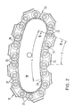
- Fig. 1 eine Seilzugvorrichtung nach der Erfindung in einer seitlichen Ansicht bei abgenommenem Gehäusedeckel, wobei einzelne Teile der Übersichtlichkeit halber weggebrochen sind,
- Fig. 2 eine Einzelheit der Fig. 1 in vergrößertem Maßstab, die das Andruckelement mit der umlaufenden Kette in einer Seitenansicht darstellt,
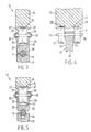
- Fig. 3 den Gegenstand der Fig. 2 in vergrößertem Maßstab in einem Teilquerschnitt nach Linie III-III, der das Profil des Druckstückes und der Seilrille sowie eine Druckrolle und die Lauffläche bei in der Längsmittelebene angeordneten Druckrollen zeigt,
- Fig. 4 ein Druckstück der Kette mit einer anderen Anordnung der Druckrollen in einer der Fig. 3 entsprechenden Darstellung und
- Fig. 5 eine andere Ausführungsform von Druckstück und Seilrille in einem analogen Teilquerschnitt nach Linie III-III der Fig. 2.
- 1 shows a cable pulling device according to the invention in a side view with the housing cover removed, individual parts being broken away for the sake of clarity,
- 2 is a detail of FIG. 1 on an enlarged scale, which shows the pressure element with the rotating chain in a side view,
- 3 shows the subject of FIG. 2 on an enlarged scale in a partial cross section along line III-III, which shows the profile of the pressure piece and the cable groove as well as a pressure roller and the running surface with pressure rollers arranged in the longitudinal center plane,
- Fig. 4 is a pressure piece of the chain with a different arrangement of the pressure rollers in a representation corresponding to FIG. 3 and
- 5 shows another embodiment of the pressure piece and rope groove in an analog partial cross section along line III-III of FIG. 2.
In den Zeichnungen bezeichnet 10 eine Seilzugvorrichtung mit durchlaufendem Zugseil 11, das vorzugsweise als Stahlseil ausgeführt ist und an dessen Lasttrum 12 die zu bewegende Last hängt, wohingegen das Lostrum 13 nur durch sein Eigengewicht belastet ist. Das Lasttrum 12 des Seils 11 läuft tangential in die Seilrille 16 einer im Gehäuse 14 drehbar gelagerten Treibscheibe 15 ein, umschlingt diese und wird als Lostrum 13 wieder tangential aus dem Gehäuse 14 geleitet. Der Antrieb der Treibscheibe 15 ist nicht Gegenstand der Erfindung und deshalb nicht dargestellt. Die Treibscheibe 15 hat bei den in den Fig. 3 und 4 dargestellten Ausführungsformen eine dem Profil des Seiles 11 angepaßte, halbkreisförmige Seilrille 16. Um die Treibfähigkeit noch zu erhöhen, kann die Seilrille 16 auch als Keilrille ausgeführt sein, wie das in Fig. 5 dargestellt ist.In the drawings, 10 denotes a cable pulling device with a
Wie aus Fig. 1 hervorgeht, wird das Seil 11 am Ende seines Umschlingungsweges von einer Druckvorrichtung 17 in die Seilrille 16 der Treibscheibe 15 gedrückt. Die Druckvorrichtung 17 besteht aus einem auf einem federbelasteten Hebel 18 kippbar gelagerten, nierenförmigen Andruckelement 19, auf dessen Lauffläche 20 sich Druckrollen 21 abwälzen. Die Druckrollen 21 sind auf den Bolzen 25 einer Gelenkkette 22 gelagert, deren Kettenglieder abwechselnd von Druckstücken 24 und an deren Außenseiten 33 montierten, auf den Bolzen 25 gelagerten Laschen 26 gebildet werden. Die Lauffläche 20 des Andruckelementes 19 verläuft auf ihrem der Treibscheibe 15 zugewandten Teil über die Länge L parallel zur Seilrille 16 der Treibscheibe 15 und wird auf jeder Seite durch je einen Führungssteg 27 begrenzt, um ein Abrutschen der Kette 22 von der Lauffläche 20 zu verhindern und um den Druckrollen 21 eine seitliche Führung zu geben.As can be seen from FIG. 1, the
Die Druckstücke 24 sind auf ihrer dem Seil 11 zugewandten Seite der Treibscheibe 15 zirkular angepaßt und haben, wie Fig. 3 und 5 zeigen, eine Profilierung 28, welche dem Außendurchmesser des Seiles 11 angepaßt ist. Diese Profilgestaltung hat den Vorteil, daß die Anpreßkraft gleichmäßig auf das Seil 11 verteilt wird, was zu einer Verminderung der Abnutzung des Seiles 11 führt. Die Druckstücke 24 sind auf der dem Andruckelement 19 zugewandten Seite in Laufrichtung der Kette 22 mit einer Nut 29 und am vorderen und hinteren Ende mit einer Querbohrung versehen, die zur Aufnahme von Bolzen 25 dienen, die gleichzeitig Achsen der Druckrollen 21 sind. An den Außenseiten 33 der Stege 31, welche die Nuten 29 in den Druckstücken 24 seitlich begrenzen, sind Laschen 26 angeordnet, die aufeinanderfolgende Druckstücke 24 miteinander verbinden und die auf den Bolzen 25 mit Sprengringen 30 gesichert sind. Der Sprengring kann auch durch einen Nietkopf ersetzt werden. Die Druckrollen 21 sind als Wälzlager mit verstärktem Außenring ausgeführt, um auch große Andruckkräfte übertragen zu können. Zum Schutz gegen Fremdkörpereintritt werden geschlossene Lager verwendet.The
Wie aus Fig. 2 hervorgeht, liegen bei der dargestellten Ausführungsform immer zwei Druckstücke 24 auf dem Seil 11 auf, während ein drittes Druckstück 24 auf das Seil aufläuft bzw. vom Seil abläuft. Um dies zu erreichen, muß der zum Seilrillengrund parallel verlaufende Teil der Lauffläche 20 des Andruckelementes 19 eine Länge L haben, die mindestens ebenso groß ist wie die Strecke S, welche zwei in der Kette aufeinanderfolgende Druckstücke 24 einnehmen. Besonders zweckmäßig ist eine Ausführungsform, bei der die Länge L der Lauffläche des Andruckelementes dreimal so groß ist wie die Strecke S, welche zwei aufeinanderfolgende Druckstücke einnehmen. Das Seil wird dann auf großer Länge in die Rille gedrückt. Diese Ausführungsform ist in der Zeichnung jedoch nicht dargestellt. Durch die geometrische Gestaltung des Andruckelementes 19 wird eine Schwenkbewegung der Druckstücke 24 unter dem Anpreßdruck verhindert und es werden Linienberuhrungen zwischen Druckstück 24 und Seil 11 vermieden, die einen hohen Seilverschleiß zur Folge haben.As can be seen from FIG. 2, in the illustrated embodiment, two
Eine weitere mögliche Anordnung der Druckrollen 21 auf dem Druckstück 24 zeigt Fig. 4. Bei dieser Anordnung sind an den Außenseiten 33 des Druckstucks 24 auf jedem Bolzen 25 zwei Druckrollen 21 fliegend gelagert, die sich auf Laufflächen 20 des Andruckelementes 19 abwälzen und von einem in der Mitte der Laufflächen 20 angeordneten Führungssteg 27 geführt werden. Hierdurch verringert sich die Flächenpressung zwischen Bolzen 25 und Druckstück 24. Bei Drehung der Treibscheibe 15 werden das Seil 11 und die Kette 22 durch Reibschluß mit gleicher Winkelgeschwindigkeit mitgenommen. Der Reibschluß kann in Kraftschluß verwandelt werden, wenn an die Treibscheibe 15 eine Art Kettenrad mit der Teilung der Kette 22 angebracht wird. Hierbei genügt es, wenn nur auf einer Seite der Kette ein Kettenrad angebracht wird, in welches die Bolzen 25 nur mit einem Ende eingreifen.A further possible arrangement of the
Die Kette 22 selbst ist keiner Zugbelastung unterworfen und läuft deshalb weitgehend verschleißfrei auf der Lauffläche 20 um das Andruckelement 19.The
Die Erfindung ist nicht auf die dargestellte und beschriebene Ausführungsform beschränkt, sondern es sind mehrere Änderungen und Ergänzungen möglich, ohne den Rahmen der Erfindung zu verlassen. Beispielsweise ist es möglich, statt des Stahlseiles einen gewirkten Kunstfasergurt als Zugmittel zu verwenden, der auf einer flachen, gummierten Treibscheibe eine großflächige, lastverteilende Auflage findet und günstige Reibwerte nutzen könnte. Die Druckstücke können anstelle von mehreren im Längsabstand voneinander angeordneten Druckrollen auch nur mit mindestens einer Druckrolle in der Mitte versehen sein. Wesentlich ist nur, daß es zu keinen Schwenkbewegungen der Druckstücke unter Anpreßdruck kommt.The invention is not limited to the illustrated and described embodiment, but several changes and additions are possible without leaving the scope of the invention. For example, instead of the steel cable, it is possible to use a knitted synthetic fiber belt as a traction device, which has a large, load-distributing support on a flat, rubberized traction sheave and could use favorable coefficients of friction. Instead of a plurality of pressure rollers arranged longitudinally apart from one another, the pressure pieces can also be provided with at least one pressure roller in the middle. It is only important that there is no pivoting movement of the pressure pieces under contact pressure.
Das Andruckelement 19 kann auch lastabhängig angestellt werden.The
Claims (11)
- Cable traction device with a driven drive pulley (15) and with a through-running rope (11) whose load run (12) is looped about the drive pulley (15) and, at the end of the loop, is pressed into the rope groove (16) of the drive pulley (15) by at least one pressure application unit (19) through the agency of pressure elements (24) arranged in the links of an endless chain (22) circulating about a guide unit, whereas the guide unit is constructed as a pressure application unit (19) and has at least one running surface (20) which is parallel to the rope groove bottom and on which there roll pressure rollers (21) which are mounted rotatably in the chain (22), characterised in that at the pressure rolls (21) pressure elements (24) are arranged resting wholly upon the rope (11).
- Device according to claim 1, characterised in that the pressure application unit (19) is mounted to be tiltable.
- Device according to claim 1 or 2, characterised in that the pressure elements (24) are arranged in every second chain link (23).
- Device according to one of claims 1 to 3, characterised in that each pressure element (24) has at least two pressure rollers (21) which are arranged spaced from one another in the direction of travel of the chain (22).
- Device according to one of claims 1 to 4, characterised in that the pressure rollers (21) are arranged in the longitudinal central plane of the pressure elements (24).
- Device according to one of claims 1 to 5, characterised in that the pressure rollers (21) are arranged at the two outer sides (33) of the pressure elements (21).
- Device according to one of claims 1 to 6, characterised in that the running surface (20) of the pressure application unit (19) is bounded by guide flanges (27) at both sides.
- Device according to one of claims 1 to 7, characterised in that the pressure rollers (21) are constructed as closed rolling contact bearings with a reinforced outer race.
- Device according to one of claims 1 to 8, characterised in that the length (L) of the running surface (20) of the pressure application unit (19) which is parallel to the rope groove bottom is at least as large as the distance occupied by two successive pressure elements (24) in the chain.
- Device according to one of claims 1 to 9, characterised in that the length (L) of the parallel part of the running surface (20) of the pressure application element (19) is three times as great as the length (S) required by the extent of two successive pressure elements (24) in the chain.
- Device according to one of claims 1 to 10, characterised in that successive pressure elements (24) are connected to one another by flat links (26) mounted on the pins (25) of the pressure rollers (21).
Applications Claiming Priority (2)
| Application Number | Priority Date | Filing Date | Title |
|---|---|---|---|
| DE3832360 | 1988-09-23 | ||
| DE3832360A DE3832360C1 (en) | 1988-09-23 | 1988-09-23 |
Publications (2)
| Publication Number | Publication Date |
|---|---|
| EP0360033A1 EP0360033A1 (en) | 1990-03-28 |
| EP0360033B1 true EP0360033B1 (en) | 1993-02-03 |
Family
ID=6363571
Family Applications (1)
| Application Number | Title | Priority Date | Filing Date |
|---|---|---|---|
| EP89115800A Expired - Lifetime EP0360033B1 (en) | 1988-09-23 | 1989-08-26 | Cable traction device |
Country Status (4)
| Country | Link |
|---|---|
| US (1) | US5082248A (en) |
| EP (1) | EP0360033B1 (en) |
| DE (1) | DE3832360C1 (en) |
| ES (1) | ES2039054T3 (en) |
Cited By (1)
| Publication number | Priority date | Publication date | Assignee | Title |
|---|---|---|---|---|
| WO2018138000A1 (en) | 2017-01-27 | 2018-08-02 | Technische Universität Dresden | Continuous cable winch |
Families Citing this family (10)
| Publication number | Priority date | Publication date | Assignee | Title |
|---|---|---|---|---|
| FR2695115B1 (en) * | 1992-09-01 | 1995-01-13 | Bretagne Hydraulique | Cable hauling device. |
| US5402985A (en) * | 1993-08-23 | 1995-04-04 | Maxwell Winches Limited | Rope winches |
| US6247680B1 (en) * | 1996-08-06 | 2001-06-19 | Abraham Cohen | Cable hoist controller |
| NO324416B1 (en) * | 1998-04-21 | 2007-10-08 | Odim Asa | Multiple traction winch |
| US6484920B1 (en) | 2000-11-01 | 2002-11-26 | Dynacon, Inc. | Cable umbilical gripper |
| AT413660B (en) * | 2004-01-27 | 2006-04-15 | Fronius Int Gmbh | DEVICE AND METHOD FOR TRANSPORTING A WIRE |
| US7021510B2 (en) * | 2004-02-12 | 2006-04-04 | David Irwin Ellingson | Cable traction apparatus and method |
| US8317160B2 (en) * | 2007-10-12 | 2012-11-27 | Safeworks, Llc | Restraint device for traction sheaves |
| US20090200529A1 (en) * | 2008-02-07 | 2009-08-13 | Safeworks, Llc | Multi-use hoist system |
| DE102012110782B4 (en) | 2012-11-09 | 2017-03-30 | Technische Universität Dresden | terminal winds |
Family Cites Families (13)
| Publication number | Priority date | Publication date | Assignee | Title |
|---|---|---|---|---|
| US1716229A (en) * | 1925-08-03 | 1929-06-04 | William P Immel | Clutch |
| US1759105A (en) * | 1928-09-07 | 1930-05-20 | Charles S Knight | Die for laying wire rope and wire-rope strands |
| US2875624A (en) * | 1955-07-25 | 1959-03-03 | Lathrop Paulson Co | Belt drive |
| US2875890A (en) * | 1957-06-10 | 1959-03-03 | Fred C Good & Sons Inc | Windlass |
| US2938707A (en) * | 1958-04-01 | 1960-05-31 | Allenbaugh Ralph | Hoisting mechanism |
| FR1431738A (en) * | 1965-01-15 | 1966-03-18 | Bertin & Cie | Method and device for driving by belts or other flexible bands |
| US3329406A (en) * | 1965-07-12 | 1967-07-04 | Henry J Flair | Push-pull capstan type cable drive |
| DE2201548C3 (en) * | 1972-01-13 | 1981-06-11 | Tractel S.A., Paris | Cable winch for unlimited cable passage |
| US3729173A (en) * | 1972-01-24 | 1973-04-24 | Tractel Sa | Endless jaw chain self-clamping winch |
| BE827486A (en) * | 1975-04-03 | 1975-07-31 | IMPROVED WINCH | |
| BE833842R (en) * | 1975-09-26 | 1976-01-16 | IMPROVED WINCH | |
| US4139178A (en) * | 1977-09-22 | 1979-02-13 | Power Climber Inc. | Hoist apparatus |
| DE3509920C2 (en) * | 1985-03-19 | 1993-11-25 | Greifzug Hebezeugbau Gmbh | Cable pull device |
-
1988
- 1988-09-23 DE DE3832360A patent/DE3832360C1/de not_active Expired - Lifetime
-
1989
- 1989-08-26 EP EP89115800A patent/EP0360033B1/en not_active Expired - Lifetime
- 1989-08-26 ES ES198989115800T patent/ES2039054T3/en not_active Expired - Lifetime
- 1989-09-15 US US07/408,114 patent/US5082248A/en not_active Expired - Fee Related
Cited By (2)
| Publication number | Priority date | Publication date | Assignee | Title |
|---|---|---|---|---|
| WO2018138000A1 (en) | 2017-01-27 | 2018-08-02 | Technische Universität Dresden | Continuous cable winch |
| DE102017101656A1 (en) | 2017-01-27 | 2018-08-02 | Technische Universität Dresden | Cable winch |
Also Published As
| Publication number | Publication date |
|---|---|
| EP0360033A1 (en) | 1990-03-28 |
| ES2039054T3 (en) | 1993-08-16 |
| DE3832360C1 (en) | 1990-02-01 |
| US5082248A (en) | 1992-01-21 |
Similar Documents
| Publication | Publication Date | Title |
|---|---|---|
| DE2522033C2 (en) | Traction drive | |
| DE102007021434B4 (en) | Aufzugsanlagenzugmittel | |
| EP0197877B1 (en) | Cable-hauling apparatus | |
| EP1555234A1 (en) | Elevator | |
| EP0360033B1 (en) | Cable traction device | |
| DE3990222B4 (en) | crawler track | |
| DE102008037537B4 (en) | Traction drive and elevator system with this traction drive | |
| DE10063844B4 (en) | Drive system for escalators and moving walks | |
| DE3540906A1 (en) | DEVICE FOR LIFTING AND LOWERING FOR PULLING LOADS | |
| DE4429223C1 (en) | Fish=plate chain for infinitely variable ratio belt contact gearbox | |
| DE19782139B4 (en) | Winch arrangement for a cable processing plant | |
| DE19947806B4 (en) | Chain drawing machine for continuous drawing of drawn material | |
| EP0088347B1 (en) | Apparatus for keeping the tension of metal strips at a constant level | |
| EP0473953B1 (en) | Belt conveyor | |
| DE10117077C1 (en) | Animal stall cleaning mechanism has scrapers moved to and fro by a continuous cable, without contact between the cable sections where their paths intersect at the drive, for long-term trouble-free working | |
| DE912225C (en) | Rope storage on the support shoe of intermediate support masts of the cable car | |
| DE3909403A1 (en) | BAND STORAGE FOR CONTINUOUS OPERATION OF ROLLING MILLS | |
| DE3017969C2 (en) | Device for parallel guidance of the tensioning drum of a vertical conveyor | |
| DE2201548C3 (en) | Cable winch for unlimited cable passage | |
| DE102019203727A1 (en) | Elevator system with profiled carrying strap | |
| DE4300271A1 (en) | Conveyor belt with cornering facility | |
| DE2039744A1 (en) | Cable | |
| DE4207992A1 (en) | TRAINING DEVICE | |
| CH619427A5 (en) | Drive arrangement for a rope run around a drivable deflection pulley | |
| DE2362726C3 (en) | Reel with grooved pulley, especially for rope-operated transport systems in mining |
Legal Events
| Date | Code | Title | Description |
|---|---|---|---|
| PUAI | Public reference made under article 153(3) epc to a published international application that has entered the european phase |
Free format text: ORIGINAL CODE: 0009012 |
|
| AK | Designated contracting states |
Kind code of ref document: A1 Designated state(s): CH ES FR GB IT LI |
|
| 17P | Request for examination filed |
Effective date: 19900629 |
|
| 17Q | First examination report despatched |
Effective date: 19910814 |
|
| ITF | It: translation for a ep patent filed |
Owner name: STUDIO INGG. FISCHETTI & WEBER |
|
| GRAA | (expected) grant |
Free format text: ORIGINAL CODE: 0009210 |
|
| STAA | Information on the status of an ep patent application or granted ep patent |
Free format text: STATUS: THE PATENT HAS BEEN GRANTED |
|
| AK | Designated contracting states |
Kind code of ref document: B1 Designated state(s): CH ES FR GB IT LI |
|
| REG | Reference to a national code |
Ref country code: GB Ref legal event code: 746 Effective date: 19930205 |
|
| GBT | Gb: translation of ep patent filed (gb section 77(6)(a)/1977) |
Effective date: 19930219 |
|
| ET | Fr: translation filed | ||
| REG | Reference to a national code |
Ref country code: ES Ref legal event code: FG2A Ref document number: 2039054 Country of ref document: ES Kind code of ref document: T3 |
|
| PLBE | No opposition filed within time limit |
Free format text: ORIGINAL CODE: 0009261 |
|
| 26N | No opposition filed | ||
| PGFP | Annual fee paid to national office [announced via postgrant information from national office to epo] |
Ref country code: FR Payment date: 19970724 Year of fee payment: 9 Ref country code: CH Payment date: 19970724 Year of fee payment: 9 |
|
| PGFP | Annual fee paid to national office [announced via postgrant information from national office to epo] |
Ref country code: GB Payment date: 19970815 Year of fee payment: 9 |
|
| PGFP | Annual fee paid to national office [announced via postgrant information from national office to epo] |
Ref country code: ES Payment date: 19970821 Year of fee payment: 9 |
|
| PG25 | Lapsed in a contracting state [announced via postgrant information from national office to epo] |
Ref country code: GB Free format text: LAPSE BECAUSE OF NON-PAYMENT OF DUE FEES Effective date: 19980826 |
|
| PG25 | Lapsed in a contracting state [announced via postgrant information from national office to epo] |
Ref country code: ES Free format text: LAPSE BECAUSE OF THE APPLICANT RENOUNCES Effective date: 19980827 |
|
| PG25 | Lapsed in a contracting state [announced via postgrant information from national office to epo] |
Ref country code: LI Free format text: LAPSE BECAUSE OF NON-PAYMENT OF DUE FEES Effective date: 19980831 Ref country code: CH Free format text: LAPSE BECAUSE OF NON-PAYMENT OF DUE FEES Effective date: 19980831 |
|
| REG | Reference to a national code |
Ref country code: CH Ref legal event code: PL |
|
| GBPC | Gb: european patent ceased through non-payment of renewal fee |
Effective date: 19980826 |
|
| PG25 | Lapsed in a contracting state [announced via postgrant information from national office to epo] |
Ref country code: FR Free format text: LAPSE BECAUSE OF NON-PAYMENT OF DUE FEES Effective date: 19990430 |
|
| REG | Reference to a national code |
Ref country code: FR Ref legal event code: ST |
|
| REG | Reference to a national code |
Ref country code: ES Ref legal event code: FD2A Effective date: 20001009 |
|
| PG25 | Lapsed in a contracting state [announced via postgrant information from national office to epo] |
Ref country code: IT Free format text: LAPSE BECAUSE OF NON-PAYMENT OF DUE FEES;WARNING: LAPSES OF ITALIAN PATENTS WITH EFFECTIVE DATE BEFORE 2007 MAY HAVE OCCURRED AT ANY TIME BEFORE 2007. THE CORRECT EFFECTIVE DATE MAY BE DIFFERENT FROM THE ONE RECORDED. Effective date: 20050826 |