EP0359986B1 - Dispositif pour soutenir le moment de torsion sur un aubage de stator de turbine à gaz - Google Patents
Dispositif pour soutenir le moment de torsion sur un aubage de stator de turbine à gaz Download PDFInfo
- Publication number
- EP0359986B1 EP0359986B1 EP89114941A EP89114941A EP0359986B1 EP 0359986 B1 EP0359986 B1 EP 0359986B1 EP 89114941 A EP89114941 A EP 89114941A EP 89114941 A EP89114941 A EP 89114941A EP 0359986 B1 EP0359986 B1 EP 0359986B1
- Authority
- EP
- European Patent Office
- Prior art keywords
- cylinder
- hole
- pin
- turbine
- vane
- Prior art date
- Legal status (The legal status is an assumption and is not a legal conclusion. Google has not performed a legal analysis and makes no representation as to the accuracy of the status listed.)
- Expired - Lifetime
Links
Images


Classifications
-
- F—MECHANICAL ENGINEERING; LIGHTING; HEATING; WEAPONS; BLASTING
- F01—MACHINES OR ENGINES IN GENERAL; ENGINE PLANTS IN GENERAL; STEAM ENGINES
- F01D—NON-POSITIVE DISPLACEMENT MACHINES OR ENGINES, e.g. STEAM TURBINES
- F01D25/00—Component parts, details, or accessories, not provided for in, or of interest apart from, other groups
- F01D25/24—Casings; Casing parts, e.g. diaphragms, casing fastenings
- F01D25/246—Fastening of diaphragms or stator-rings
-
- F—MECHANICAL ENGINEERING; LIGHTING; HEATING; WEAPONS; BLASTING
- F01—MACHINES OR ENGINES IN GENERAL; ENGINE PLANTS IN GENERAL; STEAM ENGINES
- F01D—NON-POSITIVE DISPLACEMENT MACHINES OR ENGINES, e.g. STEAM TURBINES
- F01D9/00—Stators
- F01D9/02—Nozzles; Nozzle boxes; Stator blades; Guide conduits, e.g. individual nozzles
- F01D9/04—Nozzles; Nozzle boxes; Stator blades; Guide conduits, e.g. individual nozzles forming ring or sector
- F01D9/047—Nozzle boxes
Definitions
- This invention relates generally to the turbine section of a gas turbine, and more particularly to an apparatus and method for supporting the torque load on the turbine vanes.
- Gas turbines employ a row of stationary vanes immediately upstream of each row of rotating blades to properly direct the hot gas flow to the rotating blades.
- a row of vanes comprises a plurality of vanes arrayed circumferentially around the flow path annulus.
- the vanes are retained in a turbine cylinder.
- the turbine cylinder is split longitudinally into semi-circular upper and lower halves. The halves are joined together at horizontal joints by a plurality of bolts disposed along flanged portions of the cylinder halves extending the length of each cylinder.
- Each vane comprises an airfoil, an outer shroud at its radially outboard end and an inner shroud at its radially inboard end.
- the flow of hot gas over the airfoil generates an axial force tending to urge the vane downstream.
- a support rail emanating radially from each outer shroud serves to restrain the motion of the vane in the axial direction by mating with the inner edge of a plate which is affixed at its outer edge to the turbine cylinder. Additional axial restraint may be obtained by a second support rail in the inner or outer shroud.
- the turbine cylinder In addition to the vanes, the turbine cylinder also contains a plurality of segments, arrayed around the turbine annulus, which form a ring encasing the tips of the rotating blades. To obtain optimum thermodynamic performance, the radial clearance between these segments and the tips of the rotating blades is maintained at a minimum. Hence, it is important that the turbine cylinder retain as nearly a perfectly cylindrical shape as possible. As a result of increases in the temperature of the hot gas flowing in the turbine cylinders of modern gas turbines, thermal stresses in the cylinder can cause it to ovalize and adversely affect the radial clearance between the segments and the rotating blades.
- a gas turbine comprising a plurality of vanes, having a radially outboard ends with outer shrouds being formed on said radially outboard ends, and retained in a cylinder, in a circular array concentric with said cylinder, said cylinder having a first hole extending radially from the inner surface of said cylinder and a pin disposed in said first hole and engaging said outer shrouds such that any torque load on said outer shroud is transmitted to said cylinder characterized in that said first hole extends through only a portion of the wall of said cylinder, such that said first hole has a bottom within said cylinder and that means are provided for enabling the inserting and withdrawing of said pin from engagement with said outer shroud from outside of said cylinder.
- a second, smaller hole extends from the first hole to the cylinder outer surface through the section of the flange between horizontal joint bolts which is too narrow a space for the first relatively large hole.
- the torque pin with a rod affixed to its end is inserted, from inside the cylinder, into the first hole, the rod penetrating through the second hole and extending beyond the outer surface of the flange.
- a nut, larger in diameter than the second hole is threaded onto the protruding end of the rod and prevents it from slipping back into the cylinder.
- the torque pin is engaged by backing off the nut so that the rod and pin can be moved radially inward.
- a bracket is attached to the cylinder so as to prevent the rod, and hence the torque pin from which it emanates, from moving radially outward.
- the torque pins can be disengaged and the vanes removed from outside the cylinder by removing the retaining bracket and withdrawing the pin so that it is not necessary to open the cylinder to remove the vanes.
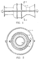
- Figure 1 shows the outer casings of the gas turbine including the turbine outer casing 9.
- Figure 2 shows the turbine outer casing 9, a turbine cylinder and a row of stationary vanes 20.
- the turbine cylinder is split longitudinally into upper and lower semi-circular halves 10 and 12 joined along a horizontal joint 13.
- Heavy flanges 14 and 17 emanate from the longitudinal edges of the cylinder halves.
- Large bolts 16 extend through holes 18 in the flange and serve to compress the flanged portions of the top and bottom cylinder halves together, as shown in Figures 3 and 4.
- the first row of vanes is typical and is comprised of a plurality of vanes 20 arrayed circumferentially around the turbine flow path annulus.
- an outer shroud 22 At the radially outboard end of each vane is an outer shroud 22.
- a support rail 24 emanates from the outer shroud. The support rail is used to affix the vane to the cylinder and restrains motion of the vane in the axial direction. This is accomplished by mating the support rail with the inner edge of a plate 58, the plate being affixed at its outer periphery of the cylinder.
- a plurality of segments 52 which form a ring encasing the tips of the rotating blades 54.
- the radial clearance 56 between these segments and the tips of the rotating blades is maintained at a minimum.
- a substantial loss of cylindricity in the cylinder will distort the shape of the ring formed by the segments 52 and result in insufficient clearance in the areas of the cylinder distorting radially inward (causing the blade tips to impact the segments) and excess clearance in the areas distorting radially outward (causing a loss in thermodynamic performance).
- the cylinders are prone to distortion as a result of thermal stresses in the cylinder.
- a first hole 32 is provided which extends radially from the inner surface of the cylinder 11 in the vicinity of each flanged portion of the cylinder. The hole penetrates through only a portion of the thickness of the flanged portion of the cylinder, stopping short before reaching the bolt holes 18.
- a second hole 34 extends from the bottom of the first hole within the cylinder to the outer surface 15 of the cylinder. Although there is insufficient clearance between bolt holes to allow the first hole to penetrate the entire thickness of the flanged portion of the cylinder, the second hole is of sufficiently small diameter to pass through the flanged portion of the cylinder between bolts without interfering with the bolts.
- the torque pin 28, utilized in the vicinity of each of the flanged portions of the cylinder, is of cylindrical shape with a diameter slightly smaller than that of the first hole.
- a key 30 is provided on one end of the pin adapted to be inserted into a key-way 26 in a support rail 24 emanating from the outer shroud of the vane 22. In operation, the key is engaged in the key-way and the opposite end of the pin is disposed in the first hole, thereby transmitting the torque load on the vane through the outer shroud and pin to the cylinder.
- a rod 36 emanates from the end of the pin opposite the key.
- the pin is inserted into the first hole from inside the cylinder.
- the pin is oriented so that the key is facing radially inward and the rod penetrates through the second hole.
- the rod is sufficiently long to protrude from the outer surface of the cylinder when the torque pin is engaged.
- the end of the rod protruding from the cylinder features screw threads 38 thus allowing a nut 40 to be threaded onto the end of the rod. Since the face of the nut is larger than the diameter of the second hole 34, the nut prevents the pin from moving radially inward and slipping back into the cylinder when the vane into which it is engaged is removed. At installation the nut is rotated onto the rod so that it pulls the pin radially outward, into its disengaged position, holding it thus until the vane is installed. The nut also allows mechanical force to be applied for disengaging a jammed pin by rotating the nut after it has seated itself against the outer surface of the cylinder, thus drawing the rod radially outward.
- a third hole 44 is drilled and tapped in the outside surface of the cylinder in the vicinity of each second hole.
- Accidental disengagement of the pin is prevented by installing a retainer bracket 42 utilizing a screw 48 disposed through a hole 46 in the bracket and threaded into the third hole 44.
- the retainer bracket has a relief 50 at one end whose depth is slightly greater than the height of the nut 40.
- a hole in the relieved portion larger than the diameter of the rod but smaller than the nut, allows it to slip over the rod 36 but prevents the nut, and therefore the rod, from moving radially outward.
Landscapes
- Engineering & Computer Science (AREA)
- Mechanical Engineering (AREA)
- General Engineering & Computer Science (AREA)
- Turbine Rotor Nozzle Sealing (AREA)
Claims (3)
Applications Claiming Priority (2)
| Application Number | Priority Date | Filing Date | Title |
|---|---|---|---|
| US07/240,292 US4957412A (en) | 1988-09-06 | 1988-09-06 | Apparatus and method for supporting the torque load on a gas turbine vane |
| US240292 | 1988-09-06 |
Publications (2)
| Publication Number | Publication Date |
|---|---|
| EP0359986A1 EP0359986A1 (fr) | 1990-03-28 |
| EP0359986B1 true EP0359986B1 (fr) | 1992-06-24 |
Family
ID=22905967
Family Applications (1)
| Application Number | Title | Priority Date | Filing Date |
|---|---|---|---|
| EP89114941A Expired - Lifetime EP0359986B1 (fr) | 1988-09-06 | 1989-08-11 | Dispositif pour soutenir le moment de torsion sur un aubage de stator de turbine à gaz |
Country Status (6)
| Country | Link |
|---|---|
| US (1) | US4957412A (fr) |
| EP (1) | EP0359986B1 (fr) |
| JP (1) | JPH02108802A (fr) |
| CA (1) | CA1304004C (fr) |
| DE (1) | DE68901903T2 (fr) |
| MX (1) | MX167090B (fr) |
Families Citing this family (11)
| Publication number | Priority date | Publication date | Assignee | Title |
|---|---|---|---|---|
| US5149248A (en) * | 1991-01-10 | 1992-09-22 | Westinghouse Electric Corp. | Apparatus and method for adapting an enlarged flow guide to an existing steam turbine |
| US5618161A (en) * | 1995-10-17 | 1997-04-08 | Westinghouse Electric Corporation | Apparatus for restraining motion of a turbo-machine stationary vane |
| JP4009801B2 (ja) * | 1998-11-09 | 2007-11-21 | 日本精工株式会社 | 転がり軸受の予圧量測定装置 |
| DE10051223A1 (de) | 2000-10-16 | 2002-04-25 | Alstom Switzerland Ltd | Verbindbare Statorelemente |
| US6773228B2 (en) * | 2002-07-03 | 2004-08-10 | General Electric Company | Methods and apparatus for turbine nozzle locks |
| US7144218B2 (en) * | 2004-04-19 | 2006-12-05 | United Technologies Corporation | Anti-rotation lock |
| US7296957B2 (en) * | 2004-05-06 | 2007-11-20 | General Electric Company | Methods and apparatus for coupling gas turbine engine components |
| US7604456B2 (en) * | 2006-04-11 | 2009-10-20 | Siemens Energy, Inc. | Vane shroud through-flow platform cover |
| DE102008060705B4 (de) * | 2008-12-05 | 2019-05-16 | Man Energy Solutions Se | Horizontal geteiltes Strömungsmaschinengehäuse |
| DE102009037620A1 (de) * | 2009-08-14 | 2011-02-17 | Mtu Aero Engines Gmbh | Strömungsmaschine |
| US8894362B2 (en) | 2010-10-21 | 2014-11-25 | Siemens Energy, Inc. | Torque pin for adjusting position of blade ring relative to rotor in a gas turbine engine |
Citations (2)
| Publication number | Priority date | Publication date | Assignee | Title |
|---|---|---|---|---|
| DE1178253B (de) * | 1962-03-03 | 1964-09-17 | Maschf Augsburg Nuernberg Ag | Axial-durchstroemte Kreiselradmaschine mit einstellbarem Deckband |
| DE2165529A1 (de) * | 1971-12-30 | 1973-07-05 | Kloeckner Humboldt Deutz Ag | Einrichtung zum zentrieren und fixieren eines koerpers |
Family Cites Families (17)
| Publication number | Priority date | Publication date | Assignee | Title |
|---|---|---|---|---|
| FR336326A (fr) * | 1903-07-20 | 1904-03-05 | Postel Vinay Ets | Perfectionnements apportés aux dispositifs de réglage des aubes intermédiaires dans les turbines à fluide élastique |
| US1019680A (en) * | 1911-03-06 | 1912-03-05 | William John Mcgavock | Nut-lock. |
| US1389006A (en) * | 1921-01-14 | 1921-08-30 | John P Noah | Nut-lock |
| GB542197A (en) * | 1940-01-25 | 1941-12-30 | British Thomson Houston Co Ltd | Improved supporting arrangement for elastic fluid turbine diaphragms |
| GB776988A (en) * | 1954-10-07 | 1957-06-12 | British Thomson Houston Co Ltd | Means for fixing nozzles in turbine casings |
| GB1277006A (en) * | 1968-06-08 | 1972-06-07 | Unbrako Ltd | Method of anchoring a cylindrical body to a support and a cylindrical body for anchorage to a support |
| US3849023A (en) * | 1973-06-28 | 1974-11-19 | Gen Electric | Stator assembly |
| US3841787A (en) * | 1973-09-05 | 1974-10-15 | Westinghouse Electric Corp | Axial flow turbine structure |
| US3892497A (en) * | 1974-05-14 | 1975-07-01 | Westinghouse Electric Corp | Axial flow turbine stationary blade and blade ring locking arrangement |
| CH589799A5 (fr) * | 1975-07-04 | 1977-07-15 | Bbc Brown Boveri & Cie | |
| JPS5932103B2 (ja) * | 1976-12-28 | 1984-08-06 | 豊和工業株式会社 | 乾燥機への海苔抄「す」装着装置 |
| US4274805A (en) * | 1978-10-02 | 1981-06-23 | United Technologies Corporation | Floating vane support |
| JPS58104308A (ja) * | 1981-12-16 | 1983-06-21 | Toshiba Corp | ノズルダイヤフラム |
| US4492517A (en) * | 1983-01-06 | 1985-01-08 | General Electric Company | Segmented inlet nozzle for gas turbine, and methods of installation |
| CH664191A5 (de) * | 1984-01-09 | 1988-02-15 | Bbc Brown Boveri & Cie | Von aussen zustellbare axialfixierung eines schaufeltraegers in einer turbine. |
| GB2164715B (en) * | 1984-09-18 | 1987-09-30 | Ford Motor Co | Preventing twisting of threaded fastener shanks |
| JPS63170505A (ja) * | 1987-01-09 | 1988-07-14 | Toshiba Corp | ノズルダイヤフラム |
-
1988
- 1988-09-06 US US07/240,292 patent/US4957412A/en not_active Expired - Lifetime
-
1989
- 1989-08-11 DE DE8989114941T patent/DE68901903T2/de not_active Expired - Lifetime
- 1989-08-11 EP EP89114941A patent/EP0359986B1/fr not_active Expired - Lifetime
- 1989-08-22 CA CA000609047A patent/CA1304004C/fr not_active Expired - Lifetime
- 1989-08-30 MX MX017356A patent/MX167090B/es unknown
- 1989-09-01 JP JP1224739A patent/JPH02108802A/ja active Pending
Patent Citations (2)
| Publication number | Priority date | Publication date | Assignee | Title |
|---|---|---|---|---|
| DE1178253B (de) * | 1962-03-03 | 1964-09-17 | Maschf Augsburg Nuernberg Ag | Axial-durchstroemte Kreiselradmaschine mit einstellbarem Deckband |
| DE2165529A1 (de) * | 1971-12-30 | 1973-07-05 | Kloeckner Humboldt Deutz Ag | Einrichtung zum zentrieren und fixieren eines koerpers |
Also Published As
| Publication number | Publication date |
|---|---|
| US4957412A (en) | 1990-09-18 |
| EP0359986A1 (fr) | 1990-03-28 |
| DE68901903T2 (de) | 1992-12-17 |
| JPH02108802A (ja) | 1990-04-20 |
| DE68901903D1 (de) | 1992-07-30 |
| CA1304004C (fr) | 1992-06-23 |
| MX167090B (es) | 1993-03-03 |
Similar Documents
| Publication | Publication Date | Title |
|---|---|---|
| US4883405A (en) | Turbine nozzle mounting arrangement | |
| US5211536A (en) | Boltless turbine nozzle/stationary seal mounting | |
| US6095750A (en) | Turbine nozzle assembly | |
| US6435820B1 (en) | Shroud assembly having C-clip retainer | |
| JP5185426B2 (ja) | ターボ機械のロータのためのロータセクション | |
| US4295785A (en) | Removable sealing gasket for distributor segments of a jet engine | |
| EP0359986B1 (fr) | Dispositif pour soutenir le moment de torsion sur un aubage de stator de turbine à gaz | |
| US8905709B2 (en) | Low-ductility open channel turbine shroud | |
| US6884028B2 (en) | Turbomachinery blade retention system | |
| US7984548B2 (en) | Method for modifying a compressor stator vane | |
| EP0475771B1 (fr) | Construction de carter de compresseur | |
| US6984108B2 (en) | Compressor stator vane | |
| US5141394A (en) | Apparatus and method for supporting a vane segment in a gas turbine | |
| US5127797A (en) | Compressor case attachment means | |
| US3799693A (en) | Bullet nose fastening arrangement | |
| US9126294B2 (en) | Tool for rotor assembly and disassembly | |
| GB2165313A (en) | Turbomachinery inner and outer casing and blade mounting arrangement | |
| US5224824A (en) | Compressor case construction | |
| US5354174A (en) | Backbone support structure for compressor | |
| GB2065785A (en) | Adjustable mounting arrangement for seal ring and inner shroud of combustion turbine engine | |
| JPH03151525A (ja) | 軸流ガスタービンの静止支持構造 | |
| US4424004A (en) | End cap for a rotor shaft of a rotary machine | |
| EP1378631A2 (fr) | Procédé et dispositif de blocage de stateur de turbine | |
| JP6740466B2 (ja) | ターボ機械のホイールを拘束する固定具 |
Legal Events
| Date | Code | Title | Description |
|---|---|---|---|
| PUAI | Public reference made under article 153(3) epc to a published international application that has entered the european phase |
Free format text: ORIGINAL CODE: 0009012 |
|
| AK | Designated contracting states |
Kind code of ref document: A1 Designated state(s): CH DE FR GB IT LI NL SE |
|
| 17P | Request for examination filed |
Effective date: 19900821 |
|
| 17Q | First examination report despatched |
Effective date: 19910816 |
|
| ITF | It: translation for a ep patent filed | ||
| GRAA | (expected) grant |
Free format text: ORIGINAL CODE: 0009210 |
|
| AK | Designated contracting states |
Kind code of ref document: B1 Designated state(s): CH DE FR GB IT LI NL SE |
|
| PG25 | Lapsed in a contracting state [announced via postgrant information from national office to epo] |
Ref country code: FR Effective date: 19920624 Ref country code: CH Effective date: 19920624 Ref country code: LI Effective date: 19920624 Ref country code: SE Effective date: 19920624 Ref country code: NL Effective date: 19920624 |
|
| REF | Corresponds to: |
Ref document number: 68901903 Country of ref document: DE Date of ref document: 19920730 |
|
| REG | Reference to a national code |
Ref country code: CH Ref legal event code: PL |
|
| EN | Fr: translation not filed | ||
| NLV1 | Nl: lapsed or annulled due to failure to fulfill the requirements of art. 29p and 29m of the patents act | ||
| PLBE | No opposition filed within time limit |
Free format text: ORIGINAL CODE: 0009261 |
|
| STAA | Information on the status of an ep patent application or granted ep patent |
Free format text: STATUS: NO OPPOSITION FILED WITHIN TIME LIMIT |
|
| 26N | No opposition filed | ||
| PGFP | Annual fee paid to national office [announced via postgrant information from national office to epo] |
Ref country code: GB Payment date: 19940627 Year of fee payment: 6 |
|
| PGFP | Annual fee paid to national office [announced via postgrant information from national office to epo] |
Ref country code: DE Payment date: 19940930 Year of fee payment: 6 |
|
| PG25 | Lapsed in a contracting state [announced via postgrant information from national office to epo] |
Ref country code: GB Effective date: 19950811 |
|
| GBPC | Gb: european patent ceased through non-payment of renewal fee |
Effective date: 19950811 |
|
| PG25 | Lapsed in a contracting state [announced via postgrant information from national office to epo] |
Ref country code: DE Effective date: 19960501 |
|
| PGFP | Annual fee paid to national office [announced via postgrant information from national office to epo] |
Ref country code: IT Payment date: 20080828 Year of fee payment: 20 |