EP0359603A1 - Moteur à courant continu ayant une connexion tressée endurante - Google Patents
Moteur à courant continu ayant une connexion tressée endurante Download PDFInfo
- Publication number
- EP0359603A1 EP0359603A1 EP89402201A EP89402201A EP0359603A1 EP 0359603 A1 EP0359603 A1 EP 0359603A1 EP 89402201 A EP89402201 A EP 89402201A EP 89402201 A EP89402201 A EP 89402201A EP 0359603 A1 EP0359603 A1 EP 0359603A1
- Authority
- EP
- European Patent Office
- Prior art keywords
- brushes
- pigtails
- brush
- motor case
- motor
- Prior art date
- Legal status (The legal status is an assumption and is not a legal conclusion. Google has not performed a legal analysis and makes no representation as to the accuracy of the status listed.)
- Granted
Links
Images


Classifications
-
- H—ELECTRICITY
- H02—GENERATION; CONVERSION OR DISTRIBUTION OF ELECTRIC POWER
- H02K—DYNAMO-ELECTRIC MACHINES
- H02K5/00—Casings; Enclosures; Supports
- H02K5/04—Casings or enclosures characterised by the shape, form or construction thereof
- H02K5/14—Means for supporting or protecting brushes or brush holders
- H02K5/143—Means for supporting or protecting brushes or brush holders for cooperation with commutators
- H02K5/148—Slidably supported brushes
-
- H—ELECTRICITY
- H01—ELECTRIC ELEMENTS
- H01R—ELECTRICALLY-CONDUCTIVE CONNECTIONS; STRUCTURAL ASSOCIATIONS OF A PLURALITY OF MUTUALLY-INSULATED ELECTRICAL CONNECTING ELEMENTS; COUPLING DEVICES; CURRENT COLLECTORS
- H01R39/00—Rotary current collectors, distributors or interrupters
- H01R39/02—Details for dynamo electric machines
- H01R39/38—Brush holders
- H01R39/40—Brush holders enabling brush movement within holder during current collection
-
- H—ELECTRICITY
- H02—GENERATION; CONVERSION OR DISTRIBUTION OF ELECTRIC POWER
- H02K—DYNAMO-ELECTRIC MACHINES
- H02K11/00—Structural association of dynamo-electric machines with electric components or with devices for shielding, monitoring or protection
- H02K11/40—Structural association with grounding devices
Definitions
- This invention relates to a multipolar dc motor having an improved pigtail arrangement, and more specifically, to brush pigtails specially arranged in a dc motor so as to improve durability against vibration, moisture, and the like.
- Japanese Utility Model Application preliminary publication No. sho 58-150355 discloses a conventional multipolar dc motor which includes a pair of positive brushes and a pair of negative brushes. These four brushes are circumferentially disposed around a commutator at various angular intervals, and are in sliding electrical contact with the commutator. All the brushes are movably received in their respective brush holders which are mounted on an annular brush stay.
- the positive brushes are approximately 120 degrees apart, and then the negative brushes are about 120 degrees apart.
- Each of the positive brushes is diametrically opposed to a negative brush.
- a positive brush and the adjacent negative brush are approximately 60 degrees apart, and the other positive brush and the adjacent negative brush are about 60 degrees apart.
- Pigtails which are lead wires for connecting the positive brushes to a power source, extend respectively from the positive brushes, being routed into the larger space between the positive brushes, and pass out of the motor case through an insulating member called "grommet" which engages with the motor case.
- the pigtails are not fixed to any part of the motor but are only loosely restrained by the grommet. Therefore, if the motor is installed in an automotive vehicle, for example, and thus is subjected to vibration, particular portions of the pigtails, such as those portions adjacent to the grommet, undergo repeated stresses. This often results in the disconnection of the pigtails in an unexpectantly short period.
- each of the pigtails is formed of many filament wires twisted or braided together, a problem can arise due to capillary action, when a liquid such as rain water and oil is wicked into the motor case through the pigtails which pass out of the motor case therethrough.
- a liquid such as rain water and oil
- the brushes are wet due to such rain water or oil, the abrasion of the brushes will be accelerated.
- Another object of the present invention is to provide a dc motor in which the wicking of liquid into the motor case, due to capillary action, is definitely prevented;
- a further object of the present invention is to provide a dc motor, in the assembling of which, the positioning of the brush stay onto the rear bracket is easy;
- a still further object of the present invention is to provide a dc motor in which pigtails for the negative brushes are appropriately arranged in order to increase reliability and service life.
- the present invention provides a dc motor including a first set of pigtails passing out of the motor case through the grommet.
- This motor has a securing means which fixes the first set of pigtails to the grommet.
- the securing means includes first and second means. The first means is stationarily engaged with the grommet, while the second means is fixedly connected to those portions of the first set of pigtails inside the motor case.
- the first set pigtails have respective sealing sections for preventing wicking of liquid by capillary action into the motor case through the first set of pigtails. These sealing sections are formed at those portion of the first set of pigtails outside the motor case. The sealing sections reduce abrasion of the brushes.
- Each of the sealing sections may be formed by bonding its constituent filament wires together by using a material such as a welding metal, a brazing metal, or a synthetic adhesive resin.
- the grommet is engaged with the rear bracket, and the brush stay has an engaging portion engaging with the grommet.
- the location of the engaging portion on the brush stay should be such that, when the engaging portion is engaged with the grommet, the brush stay is properly positioned on the rear bracket to be fastened to the rear bracket.
- the brush stay can be properly positioned on the rear bracket. This arrangement facilitates the fastening of the brush stay to the rear bracket, and thus enhances workability during assembly.
- the angular interval is more than 90° between two brushes of the same polarity to which two pigtails of the second set are connected.
- the two brushes may be adjacent to each other without any brush interposed therebetween, and the brush stay may have a grounded terminal member projecting generally parallel to the axis of the commutator from that portion of the inner peripheral edge of the annular brush stay between the two brushes.
- the two pigtails of the second set are routed into the space between the two brushes and are electrically connected at their end portions to the terminal member.
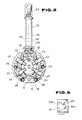
- reference numeral 10 denotes a six-pole dc motor according to the present invention.
- Magnets (not shown) are disposed on the inner peripheral surface of a cylindrical yoke 12 which is a part of a motor case of the motor 10.
- An armature 14 is disposed within the yoke 12, and the shaft 13 of the armature 14 is rotatably supported by opposite end brackets (only a rear bracket 18 is shown) of the motor case.
- An annular brush stay 16 is mounted on the inner face of the rear bracket 18 by means of screws 20 so as to be disposed around the end portion of the armature shaft 13.
- the brush stay 16 is formed of an annular metal plate to which an annular insulating plate is attached.
- each of the brush holders 22, 22, 23 and 23 is made of a metal plate formed into a gutter-like configuration having a rectangular cross section, and has one or two cutouts formed in its side walls, as will be described later on.
- These brush holders 22, 22, 23 and 23, as shown in Fig. 2 are circumferentially arranged at angular intervals on the annular brush stay 16 to surround a commutator 29 which fixedly fits around the end portion of the armature shaft 13.
- the brush stay 16 and the inner face of each brush holder define a space, extending along a radial direction of the commutator 29, for receiving a carbon brush 24 or 26.
- two of the brush holders 22 and 22 receive a pair of positive brushes 24 and 24, respectively, for the radial movement of the positive brushes 24 and 24, while the other two brush holders 23 and 23 receive a pair of negative brushes 26 and 26, respectively, for their radial movement.
- the positive brushes 24 and 24 are diametrically opposed to the negative brushes 26 and 26, respectively.
- the angular interval between the brush holders 22 and 22 for the positive brushes 24 and 24, that is, the angular interval between the positive brushes 24 and 24, is equal to that between the negative brushes 26 and 26, and is more than 90°, and preferably around 120°; the angular interval between each positive brush 24 and the adjacent negative brush 26 is less than 90°, and preferably 60°.
- These brushes 24, 24, 26 and 26 are in sliding electrical contact with the commutator 29.
- the positive brushes 24 and 24 are connected to a power source (not shown), and the negative brushes 26 and 26 are grounded via the motor case.
- spiral springs 28 are mounted on the brush stay to urge the brushes 24, 24, 26 and 26 against the peripheral face of the commutator 29.
- Two of the springs 28 and 28, for urging the positive brushes 24 and 24, are disposed respectively in the smaller spaces between the positive and negative brushes 24 and 26 while the other two springs 28 and 28, for urging the negative brushes 26 and 26, are disposed in the larger space between the negative brushes 26 and 26.
- All these spiral springs 28 are fixed at their central ends to the brush stay 16, and are in contact at their outer ends respectively with the outer ends of the brushes, which are opposite to the ends of the brushes contacting the commutator 29.
- the brush holders 22, 22, 23 and 23 have radially extending first cutouts 30, respectively.
- the first cutouts 30 and 30 of the brush holders 22 and 22, as shown in Fig, 5, are formed in respective side walls of the brush holders 22 and 22, circumferentially opposing each other.
- the first cutouts 30 and 30 of the brush holders 23 and 23, as shown in Fig, 4, are formed in respective side walls of the brush holders 23 and 23, circumferentially opposing each other.
- These first cutouts 30 expose parts of the internal brushes 24, 24, 26 and 26 to the outside. To these exposed parts of the brushes 24, 24, 26 and 26, pigtails 32, 32, 34 and 34 are connected, respectively.
- the ends of the pigtails 32, 32, 34 and 34 are embedded in and fixed to the exposed parts of the brushes 24, 24, 26 and 26.
- These pigtails 32, 32, 34 and 34 are lead wires, each being formed of many electrically conductive filament wires twisted or braided together, and are adapted to connect the brushes 24, 24, 26 and 26 to the stationary positive terminal (not shown) of a power source or a grounded part such as the motor case.
- the pigtails 32 and 32 which are connected to the positive brushes 24 and 24 are routed into the larger space between the positive brushes 24 and 24. Then, the pigtails 32 and 32, as shown in Fig.
- the other two pigtails 34 and 34 which extend from the negative brushes 26 and 26, as shown in Fig. 4, are routed into the larger space between the negative brushes 26 and 26, and are connected at their end portion, by means of welding, to a T-shaped plate-like terminal fillet 35 which projects from that portion of the inner periphery of the brush stay 16 between the negative brushes 26 and 26.
- the terminal fillet 35 is a part of the brush stay's metal plate folded at a right angle to the brush stay 16. That is to say, the pigtails 34 and 34 are grounded through the brush stay 16 and the motor case.
- the terminal fillet 35 includes a proximal portion and a wing portion.
- the proximal portion of the terminal fillet 35 extends axially from the brush stay 16, while the wing portion of the terminal fillet 35 extends circumferentially from the proximal portion toward both the negative brushes 26 and 26.
- Each of the proximal and wing portions has inner and outer surfaces, the inner surface facing the commutator, the outer surface being opposite to the inner surface. More specifically, the pigtails 34 and 34 extend generally circumferentially from the respective negative brushes 26 and 26, and are laid or rest on the outer surface of the wing portion of the terminal fillet 35.
- the end portions of the pigtails 34 and 34 are bent to the brush stay 16 and welded to the outer surface of the proximal portion of the terminal fillet 35. That is, these end portions of the pigtails 34 and 34 are disposed generally perpendicularly to the brush stay 16 or generally parallel to the axis of the commutator 29.
- this pigtail arrangement it is not necessary to route the pigtails 34 and 34 in a radial direction to lead them to the outside of the motor case, and thus it is also not necessary to lengthen the pigtails 34 and 34 to avoid their interference with the springs 28 and 28 in the smaller space between the negative brushes 26 and 26. Accordingly, the lengths of the pigtails 34 and 34 can be minimized to restrain the vibration of pigtails 34 and 34 caused, for example, by the movement of an automotive vehicle in which the motor is installed.
- each of the first cutouts 30 and 30 of the brush holder 23 and 23 has a radially inner section 30a of a smaller width and a radially outer section 30b of a larger width.
- the cutouts 30 and 30 are so formed that the pigtails 34 and 34 pass out of the brush holders 23 and 23 through the inner sections 30a and 30a of the cutouts 30 and 30, and the outer ends of the springs 28 and 28 for the negative brushes 26 and 26 extend into the brush holders 23 and 23 through the outer sections 30b and 30b of the cutouts 30 and 30.
- the pigtails 32, 32, 34 and 34 and the outer ends of the springs 28 and 28 are radially movable within the cutouts 30 so as to follow the movement of the brushes 24, 24, 26 and 26.
- the brush holders 22 and 22 further have radially extending second cutouts 31, respectively.
- These second cutouts 31 and 31 are formed in respective side walls of the brush holders 22 and 22, opposite to the side walls in which the first cutouts 30 and 30 are formed.
- These second cutouts 31 and 31 expose parts of the positive brushes 24 and 24 to the outside.
- the outer ends of the springs 28 and 28 for the positive brushes 24 and 24 extend into the brush holders 22 and 22 through the second cutouts 31 and 31 to contact the outer ends of the brushes 24 and 24.
- These outer ends of the springs 28 and 28 are radially movable within the cutouts 31 and 31 so as to follow the movement of the brushes 24 and 24.
- the grommet 38 has inner and outer faces and a peripheral face, wherein the inner face is opposed to the brushes 22 and 22 and the like, and wherein the outer face is exposed to the external atmosphere.
- This grommet 38 is integrally formed with a tubular member 36 which is joined at its inner end to the outer face of the grommet 38.
- the grommet 38, as well as the tubular member 36, is made of a flexible insulating material such as rubber, synthetic resin and the like, and encloses the pigtails 32 and 32, i.e., those portions of the pigtails 32 and 32 outside the motor case, so as to serve as an insulating and waterproof sheath.
- the reference numeral 40 designates a through-hole formed in the grommet 38 and communicating with the internal space of tubular member 36.
- the grommet 38 has a first groove 44 peripherally extending completely along the peripheral face thereof.
- the rear bracket 18 of the motor case as shown in Fig 1, has an opening in the form of a cutout 42 for allowing the pigtails 32 and 32 to pass therethrough. That portion of the rear bracket 18 defining the cutout 42 fits in the first groove 44 of the grommet 38 so that the grommet 38 is engaged with the rear bracket 18, and prevents rain water and dust from coming into the motor case through the cutout 42.
- the grommet 38 further has a rectangular projection 46 extending from that section of the inner face of the grommet 38 beside the through-hole 40.
- This projection 46 has a second groove 50 and a pocket 54.
- the second groove 50 extends peripherally along the lower and the opposite side faces, as viewed in Fig. 7, of the projection 46, while the pocket 54 is formed in the upper face of the projection 46 and extends generally parallel to the axis of the commutator 29.
- the second groove 50 fittingly receives a U-shaped engaging fillet 48 (see Fig. 3) which extends perpendicularly from the outer periphery of the brush stay 16.
- This engaging fillet 48 is formed of a part of the brush stay bent at a right angle toward the yoke 12.
- the pocket 54 fittingly receives a securing means in the form of a pigtail-holder 52 which is a generally U-shaped metal plate piece with a tail 56 and a pair of nails 58 and 58. More specifically, the tail 56 is a portion for fitting into the pocket 54, and the nails 58 and 58 are portions for holding those portions of the pigtails 32 and 32 inside the motor case.
- the holder 52 is made of steel, for example, which can be easily subjected to plastic deformation. As shown in Fig. 7, the nails 58 and 58 of the holder 52 are bent to firmly grasp the pigtails 32 and 32, respectively. Accordingly, the pigtails 32 and 32 are fixed to the grommet 38 by mean of the holder 52 so that radial movement, as well as axial movement, of those portions of the the pigtails 32 and 32 inside the motor case is restrained.
- the pigtails 32 and 32 may be covered with a sheath made of a insulating material such as a glass fiber, rubber, synthetic resin, and the like.
- those portions of the pigtails 32 and 32 adjacent to the through-hole 40 of the grommet 38 are fixed to the grommet 38. Therefore, the lengths of the pigtails 32 and 32 between the holder 52 and the respective positive brushes 24 and 24 are maintained constant. Even if an external force that may loosen the pigtails 32 and 32 is applied to the pigtails 32 and 32, this loosening force is obstructed by the holder, and thus does not result in the loosening of the pigtails 32 and 32 inside the motor case. Therefore, it is possible to lengthen those portions of the pigtails 32 and 32 between the holder 52 and the brushes 24 to the maximal lengths to enhance workability during wiring work. Moreover, under operating conditions subject to severe vibration, the pigtails 32 and 32 do not move around to any significant degree and thus cause no contact with other metal portions and no short-circuits.
- the brush stay 16 is fastened to the inner face of the rear bracket 18 by means of screws 20 and 20. That portion of the rear bracket l8 defining the cutout 42 fits in the first groove 44 of the grommet 38, while the engaging fillet 48 of the brush stay fits in the second groove 50 of the grommet 38.
- the rear bracket 18 and the brush stay 16 are, thus, unitarily assembled.
- the grommet 38 is fixedly clamped between the rear bracket 18 and the yoke 12 so that the pigtails 32 are appropriately positioned relative to the motor case.
- the grommet 38 with the pigtail 32 passing therethrough is mounted on the brush stay 16 by inserting the engaging fillet 48 into the second groove 50 of the grommet 38. Then, the brush stay 16 with the grommet 38 and the brushes 24, 24, 26 and 26 is disposed around the commutator 29. After that, the rear bracket 18 is placed onto the corresponding end of the yoke 12 to cover the brush stay 16, and at the same time, that portion of the rear bracket 18 defining the cutout 42 is fitted in the first groove 44 of the grommet 38 so that the rear bracket 18 is properly positioned over the brush stay 16. Lastly, the rear bracket 18 is fastened to the brush stay 16 by means of the screws 20 and 20.
- sealing sections 62 and 62 are formed on those portions of the pigtails 32 and 32 covered by the tubular member 36.
- Each of the sealing sections 62 and 62 is formed by bonding the filament wires of the pigtail 32 together by means of, for example, spot welding. That is, at these sealing sections 62 and 62, welding or brazing metals close the gaps among the filament wires and prevent the wicking of water or oil due to capillary action into the motor case.
- the sealing sections 62 and 62 of the pigtails 32 and 32 are disposed at the same distance from the grommet 38 (see Fig.
- sealing sections 62 and 62 are located at similar positions on their respective pigtails 32 and 32, the pigtails 32 of the same standard can be used. This fact is advantageous in maintaining the parts of the motor.
- a welding or brazing metal but also a synthetic adhesive resin, may be utilized. More specifically, a part of each pigtail 32 may be impregnated with the adhesive resin to form a sealing section.
- a terminal strip 64 is welded and connected to the outer ends of the pigtails 32 and 32, located outside the grommet 38. This terminal strip 64 facilitates the assembly works for connecting the pigtails 32 and 32 to an electric source.
Landscapes
- Engineering & Computer Science (AREA)
- Power Engineering (AREA)
- Motor Or Generator Frames (AREA)
Applications Claiming Priority (8)
| Application Number | Priority Date | Filing Date | Title |
|---|---|---|---|
| JP115639/88U | 1988-09-02 | ||
| JP11563988U JPH0632766Y2 (ja) | 1988-09-02 | 1988-09-02 | 多極モータにおけるピグテール配線構造 |
| JP116563/88U | 1988-09-05 | ||
| JP1988116563U JPH055824Y2 (fr) | 1988-09-05 | 1988-09-05 | |
| JP116562/88U | 1988-09-05 | ||
| JP1988116562U JPH058788Y2 (fr) | 1988-09-05 | 1988-09-05 | |
| JP123193/88U | 1988-09-20 | ||
| JP12319388U JPH0635649Y2 (ja) | 1988-09-20 | 1988-09-20 | モータにおけるピグテールの外部引出し構造 |
Publications (2)
| Publication Number | Publication Date |
|---|---|
| EP0359603A1 true EP0359603A1 (fr) | 1990-03-21 |
| EP0359603B1 EP0359603B1 (fr) | 1993-10-27 |
Family
ID=27470276
Family Applications (1)
| Application Number | Title | Priority Date | Filing Date |
|---|---|---|---|
| EP89402201A Expired - Lifetime EP0359603B1 (fr) | 1988-09-02 | 1989-08-02 | Moteur à courant continu ayant une connexion tressée endurante |
Country Status (4)
| Country | Link |
|---|---|
| US (1) | US4965478A (fr) |
| EP (1) | EP0359603B1 (fr) |
| CA (1) | CA1318715C (fr) |
| DE (1) | DE68910251T2 (fr) |
Cited By (14)
| Publication number | Priority date | Publication date | Assignee | Title |
|---|---|---|---|---|
| EP0612137A1 (fr) * | 1993-02-19 | 1994-08-24 | Mitsuba Electric Manufacturing Co., Ltd. | Dispositif de balais |
| EP0986163A1 (fr) * | 1997-05-26 | 2000-03-15 | Mitsubishi Denki Kabushiki Kaisha | Porte-balais |
| EP1032111A1 (fr) * | 1999-02-25 | 2000-08-30 | Denso Corporation | Dispositif porte-balais pour moteur DC |
| WO2003071661A1 (fr) * | 2002-02-18 | 2003-08-28 | Siemens Aktiengesellschaft | Unite de fixation destinee a un moteur electrique |
| EP1424762A1 (fr) * | 2002-11-30 | 2004-06-02 | Johnson Electric S.A. | Ensemble de flasque d'extrémité |
| DE102004004745A1 (de) * | 2004-01-30 | 2005-08-18 | Robert Bosch Gmbh | Bürstenhalter für eine Elektromaschine |
| EP1710893A1 (fr) * | 2005-04-06 | 2006-10-11 | Siemens Aktiengesellschaft | Système de balais pour un servomoteur électrique |
| FR2908245A1 (fr) * | 2006-11-06 | 2008-05-09 | Valeo Equip Electr Moteur | Dispositif de balais de machine electrique tournante, tel qu'un demarreur |
| DE102008042156A1 (de) | 2008-09-17 | 2010-03-18 | Robert Bosch Gmbh | Sechspolige Gleichstrommaschine |
| EP2267872A1 (fr) * | 2008-03-24 | 2010-12-29 | Mitsuba Corporation | Moteur |
| WO2017013353A1 (fr) * | 2015-07-20 | 2017-01-26 | Valeo Equipements Electriques Moteur | Porte-balais ameliore de moteur electrique de demarreur de vehicule automobile |
| US10008911B2 (en) | 2013-12-20 | 2018-06-26 | Johnson Elecric S.A. | Brush assembly |
| CN109067070A (zh) * | 2018-08-10 | 2018-12-21 | 成都中车电机有限公司 | 一种直流牵引电动机刷握安装结构及方法 |
| US10491080B2 (en) | 2013-12-20 | 2019-11-26 | Johnson Electric International AG | Brush assembly |
Families Citing this family (12)
| Publication number | Priority date | Publication date | Assignee | Title |
|---|---|---|---|---|
| US5101129A (en) * | 1989-12-18 | 1992-03-31 | General Electric Company | Mounting bushing for an overload protector |
| US4998035A (en) * | 1990-07-26 | 1991-03-05 | American Standard Inc. | Method for attaching a motor lead restraint device to a compressor pump |
| US5519273A (en) * | 1994-09-08 | 1996-05-21 | General Electric Company | Fitting for coupling an electric motor and a motor lead protective conduit |
| US5777409A (en) * | 1996-02-13 | 1998-07-07 | General Electric Company | Methods and apparatus for coupling an electric motor and a motor lead protective conduit |
| US5856717A (en) * | 1997-03-31 | 1999-01-05 | Reliance Electric Industrial Company | Enclosure for an electric motor |
| TW388191B (en) * | 1997-06-27 | 2000-04-21 | Samsung Electronics Co Ltd | Apparatus for securing cable and electric device comprising the same |
| JP3345365B2 (ja) * | 1999-01-29 | 2002-11-18 | マブチモーター株式会社 | 小型モータ |
| DE60010637T2 (de) | 1999-12-24 | 2005-05-19 | Denso Corp., Kariya | Leitungsdrahteinheit einer elektrischen rotierenden Gleichstrommaschine |
| US6495755B2 (en) | 2001-04-26 | 2002-12-17 | Emerson Electric Co. | Self-locking wiring grommet |
| US6622537B2 (en) | 2001-07-16 | 2003-09-23 | Newfrey Llc | Deadbolt with LED and wiring harness |
| JP4279582B2 (ja) * | 2003-03-26 | 2009-06-17 | 株式会社ショーワ | 電動モータ |
| JP4687439B2 (ja) * | 2005-12-16 | 2011-05-25 | 株式会社デンソー | 回転電機 |
Citations (6)
| Publication number | Priority date | Publication date | Assignee | Title |
|---|---|---|---|---|
| DE6802396U (de) * | 1967-12-14 | 1969-03-13 | Lenco Italiana S P A | Elektromotor mit kleinen abmessungen, insbesondere fuer scheibendrehvorrichtungen, magnetische registriereinrichtungen oder- geraete usw. |
| US4355253A (en) * | 1981-02-27 | 1982-10-19 | Briggs & Stratton Corp. | Combination end bell and brush holder for a dynamoelectric machine |
| GB2118377A (en) * | 1982-04-08 | 1983-10-26 | Mitsubishi Electric Corp | Magneto-type d-c electric motor |
| US4413200A (en) * | 1981-11-04 | 1983-11-01 | Allied Corporation | Dynamoelectric machine with cartridge brush holder |
| FR2530885A1 (fr) * | 1982-07-22 | 1984-01-27 | Marchal Equip Auto | Sous-ensemble d'alimentation pour moteur electrique, et moteur comprenant un tel sous-ensemble |
| EP0219681A1 (fr) * | 1985-09-26 | 1987-04-29 | Siemens Aktiengesellschaft | Ensemble fermé à moteur et réducteur |
Family Cites Families (17)
| Publication number | Priority date | Publication date | Assignee | Title |
|---|---|---|---|---|
| DE488796C (de) * | 1930-01-08 | Hans Carlsen | Rohrfoermige Wanddurchfuehrung fuer elektrische Leitungen | |
| US2276818A (en) * | 1939-11-04 | 1942-03-17 | Gen Electric | Electrical connecting device |
| US2717792A (en) * | 1952-01-30 | 1955-09-13 | Beech Aircraft Corp | Seal for aircraft control member |
| US4407042A (en) * | 1981-10-02 | 1983-10-04 | General Motors Corporation | Grommet assembly with panel attaching means |
| JPS58150355A (ja) * | 1982-03-03 | 1983-09-07 | Hitachi Ltd | 集線スイツチ試験方式 |
| JPS5932199A (ja) * | 1982-08-16 | 1984-02-21 | 三菱電機株式会社 | 電子機器 |
| JPS5934461A (ja) * | 1982-08-23 | 1984-02-24 | Toyota Motor Corp | 内燃機関の排気ガス浄化装置 |
| JPS5966360A (ja) * | 1982-10-07 | 1984-04-14 | 株式会社幸袋工作所 | 破砕整粒機 |
| FR2535061A1 (fr) * | 1982-10-20 | 1984-04-27 | Enertec | Compteur electronique pour la mesure des energies active et reactive sur un reseau triphase |
| JPS59189466A (ja) * | 1983-04-13 | 1984-10-27 | Fujitsu Ltd | 端末切替方式 |
| FR2548472B1 (fr) * | 1983-07-01 | 1985-11-08 | Paris & Du Rhone | Dispositif pour le maintien et le centrage d'une rondelle porte-balais, en cours de montage, sur une machine tournante electrique a collecteur |
| JPS6055274A (ja) * | 1983-09-06 | 1985-03-30 | Tdk Corp | 表面電位センサ |
| JPS6073372A (ja) * | 1983-09-30 | 1985-04-25 | Yazaki Corp | 電力ケ−ブルの部分放電測定における抵抗分離構造 |
| JPS59109288A (ja) * | 1983-11-28 | 1984-06-23 | Toshiba Corp | 廃水処理装置 |
| JPS60128469A (ja) * | 1983-12-15 | 1985-07-09 | Fuji Xerox Co Ltd | トナ−残量検知装置 |
| US4678146A (en) * | 1985-12-05 | 1987-07-07 | General Motors Corporation | Universal grommet retainer |
| US4678867A (en) * | 1986-08-01 | 1987-07-07 | Eaton Corporation | Electrical device with protective shroud for flexible electrical cable extending therefrom |
-
1989
- 1989-07-25 US US07/385,245 patent/US4965478A/en not_active Expired - Lifetime
- 1989-07-26 CA CA000606745A patent/CA1318715C/fr not_active Expired - Fee Related
- 1989-08-02 DE DE89402201T patent/DE68910251T2/de not_active Expired - Fee Related
- 1989-08-02 EP EP89402201A patent/EP0359603B1/fr not_active Expired - Lifetime
Patent Citations (6)
| Publication number | Priority date | Publication date | Assignee | Title |
|---|---|---|---|---|
| DE6802396U (de) * | 1967-12-14 | 1969-03-13 | Lenco Italiana S P A | Elektromotor mit kleinen abmessungen, insbesondere fuer scheibendrehvorrichtungen, magnetische registriereinrichtungen oder- geraete usw. |
| US4355253A (en) * | 1981-02-27 | 1982-10-19 | Briggs & Stratton Corp. | Combination end bell and brush holder for a dynamoelectric machine |
| US4413200A (en) * | 1981-11-04 | 1983-11-01 | Allied Corporation | Dynamoelectric machine with cartridge brush holder |
| GB2118377A (en) * | 1982-04-08 | 1983-10-26 | Mitsubishi Electric Corp | Magneto-type d-c electric motor |
| FR2530885A1 (fr) * | 1982-07-22 | 1984-01-27 | Marchal Equip Auto | Sous-ensemble d'alimentation pour moteur electrique, et moteur comprenant un tel sous-ensemble |
| EP0219681A1 (fr) * | 1985-09-26 | 1987-04-29 | Siemens Aktiengesellschaft | Ensemble fermé à moteur et réducteur |
Cited By (25)
| Publication number | Priority date | Publication date | Assignee | Title |
|---|---|---|---|---|
| EP0612137A1 (fr) * | 1993-02-19 | 1994-08-24 | Mitsuba Electric Manufacturing Co., Ltd. | Dispositif de balais |
| US5414318A (en) * | 1993-02-19 | 1995-05-09 | Mitsuba Electric Manufacturing Co., Ltd. | Brush device |
| EP0986163A1 (fr) * | 1997-05-26 | 2000-03-15 | Mitsubishi Denki Kabushiki Kaisha | Porte-balais |
| EP0986163A4 (fr) * | 1997-05-26 | 2001-03-21 | Mitsubishi Electric Corp | Porte-balais |
| US6326716B1 (en) | 1999-02-22 | 2001-12-04 | Denso Corporation | Brush holder arrangement of DC motor |
| EP1032111A1 (fr) * | 1999-02-25 | 2000-08-30 | Denso Corporation | Dispositif porte-balais pour moteur DC |
| EP1453183A3 (fr) * | 1999-02-25 | 2005-09-07 | Denso Corporation | Dispositif porte-balais pour moteur DC |
| WO2003071661A1 (fr) * | 2002-02-18 | 2003-08-28 | Siemens Aktiengesellschaft | Unite de fixation destinee a un moteur electrique |
| US7215050B2 (en) | 2002-02-18 | 2007-05-08 | Siemens Ag | Fixing unit for an electric motor |
| EP1424762A1 (fr) * | 2002-11-30 | 2004-06-02 | Johnson Electric S.A. | Ensemble de flasque d'extrémité |
| US6849986B2 (en) | 2002-11-30 | 2005-02-01 | Johnson Electric S.A. | End cap assembly |
| DE102004004745A1 (de) * | 2004-01-30 | 2005-08-18 | Robert Bosch Gmbh | Bürstenhalter für eine Elektromaschine |
| WO2006106064A1 (fr) * | 2005-04-06 | 2006-10-12 | Siemens Vdo Automotive Ag | Systeme a balais pour mecanisme de commande a moteur electrique |
| EP1710893A1 (fr) * | 2005-04-06 | 2006-10-11 | Siemens Aktiengesellschaft | Système de balais pour un servomoteur électrique |
| FR2908245A1 (fr) * | 2006-11-06 | 2008-05-09 | Valeo Equip Electr Moteur | Dispositif de balais de machine electrique tournante, tel qu'un demarreur |
| EP2267872A1 (fr) * | 2008-03-24 | 2010-12-29 | Mitsuba Corporation | Moteur |
| EP2267872A4 (fr) * | 2008-03-24 | 2017-03-29 | Mitsuba Corporation | Moteur |
| EP3940933A1 (fr) * | 2008-03-24 | 2022-01-19 | Mitsuba Corporation | Moteur |
| DE102008042156A1 (de) | 2008-09-17 | 2010-03-18 | Robert Bosch Gmbh | Sechspolige Gleichstrommaschine |
| US10008911B2 (en) | 2013-12-20 | 2018-06-26 | Johnson Elecric S.A. | Brush assembly |
| US10491080B2 (en) | 2013-12-20 | 2019-11-26 | Johnson Electric International AG | Brush assembly |
| WO2017013353A1 (fr) * | 2015-07-20 | 2017-01-26 | Valeo Equipements Electriques Moteur | Porte-balais ameliore de moteur electrique de demarreur de vehicule automobile |
| FR3039330A1 (fr) * | 2015-07-20 | 2017-01-27 | Valeo Equip Electr Moteur | Porte-balais ameliore de moteur electrique de demarreur de vehicule automobile |
| CN109067070A (zh) * | 2018-08-10 | 2018-12-21 | 成都中车电机有限公司 | 一种直流牵引电动机刷握安装结构及方法 |
| CN109067070B (zh) * | 2018-08-10 | 2023-10-17 | 成都中车电机有限公司 | 一种直流牵引电动机刷握安装结构 |
Also Published As
| Publication number | Publication date |
|---|---|
| EP0359603B1 (fr) | 1993-10-27 |
| DE68910251D1 (de) | 1993-12-02 |
| US4965478A (en) | 1990-10-23 |
| DE68910251T2 (de) | 1994-05-05 |
| CA1318715C (fr) | 1993-06-01 |
Similar Documents
| Publication | Publication Date | Title |
|---|---|---|
| EP0359603B1 (fr) | Moteur à courant continu ayant une connexion tressée endurante | |
| US4475053A (en) | Brush-holder for electrical machines | |
| CA1171128A (fr) | Chape porte-balai pour machine dynamoelectrique | |
| US5773907A (en) | Brush holder assemblies having novel brush holders | |
| US5689148A (en) | Multi-pole, two-speed brush holder assembly | |
| US5148073A (en) | Wiring device in direct current machine | |
| US7531938B2 (en) | Insertable brush holder assembly for electric motor | |
| JP4991932B2 (ja) | ブッシング形コンデンサを備えた直流モータ | |
| EP0511876B1 (fr) | Dispositif de fixation d'une bobine de réactance pour moteurs miniatures | |
| EP0645872B1 (fr) | Moteur miniature | |
| US4340832A (en) | Dynamoelectric machine brush holder | |
| US7687967B2 (en) | Brush assembly for alternator easy to install and capable of reliably preventing entrance of foreign matters | |
| CN110212680B (zh) | 电刷保持件 | |
| JPH09308203A (ja) | ブラシ付き直流電動機 | |
| US7414346B1 (en) | Brush holder for dynamo-electric machine | |
| JPS6223248Y2 (fr) | ||
| KR900003401Y1 (ko) | 모터 | |
| US5099163A (en) | Brush device for rotary electric machine | |
| EP0986164B1 (fr) | Porte-balais | |
| JP2577765Y2 (ja) | ブラシ保持部構造 | |
| JPH0998559A (ja) | 直流モータにおけるブラシ配線部構造 | |
| JP2501469B2 (ja) | 電動機 | |
| US5543675A (en) | Brush leaf means | |
| JP2006121805A (ja) | ブラシ装置 | |
| JPH038074Y2 (fr) |
Legal Events
| Date | Code | Title | Description |
|---|---|---|---|
| PUAI | Public reference made under article 153(3) epc to a published international application that has entered the european phase |
Free format text: ORIGINAL CODE: 0009012 |
|
| AK | Designated contracting states |
Kind code of ref document: A1 Designated state(s): DE FR GB |
|
| 17P | Request for examination filed |
Effective date: 19900525 |
|
| 17Q | First examination report despatched |
Effective date: 19920717 |
|
| GRAA | (expected) grant |
Free format text: ORIGINAL CODE: 0009210 |
|
| AK | Designated contracting states |
Kind code of ref document: B1 Designated state(s): DE FR GB |
|
| REF | Corresponds to: |
Ref document number: 68910251 Country of ref document: DE Date of ref document: 19931202 |
|
| ET | Fr: translation filed | ||
| PLBE | No opposition filed within time limit |
Free format text: ORIGINAL CODE: 0009261 |
|
| STAA | Information on the status of an ep patent application or granted ep patent |
Free format text: STATUS: NO OPPOSITION FILED WITHIN TIME LIMIT |
|
| 26N | No opposition filed | ||
| REG | Reference to a national code |
Ref country code: FR Ref legal event code: RM Ref country code: FR Ref legal event code: CD |
|
| REG | Reference to a national code |
Ref country code: GB Ref legal event code: IF02 |
|
| PGFP | Annual fee paid to national office [announced via postgrant information from national office to epo] |
Ref country code: GB Payment date: 20050727 Year of fee payment: 17 |
|
| GBPC | Gb: european patent ceased through non-payment of renewal fee |
Effective date: 20060802 |
|
| PGFP | Annual fee paid to national office [announced via postgrant information from national office to epo] |
Ref country code: DE Payment date: 20070726 Year of fee payment: 19 |
|
| PG25 | Lapsed in a contracting state [announced via postgrant information from national office to epo] |
Ref country code: GB Free format text: LAPSE BECAUSE OF NON-PAYMENT OF DUE FEES Effective date: 20060802 |
|
| PGFP | Annual fee paid to national office [announced via postgrant information from national office to epo] |
Ref country code: FR Payment date: 20070808 Year of fee payment: 19 |
|
| REG | Reference to a national code |
Ref country code: FR Ref legal event code: ST Effective date: 20090430 |
|
| PG25 | Lapsed in a contracting state [announced via postgrant information from national office to epo] |
Ref country code: FR Free format text: LAPSE BECAUSE OF NON-PAYMENT OF DUE FEES Effective date: 20080901 Ref country code: DE Free format text: LAPSE BECAUSE OF NON-PAYMENT OF DUE FEES Effective date: 20090303 |