EP0359046A1 - Connecting element - Google Patents
Connecting element Download PDFInfo
- Publication number
- EP0359046A1 EP0359046A1 EP89116080A EP89116080A EP0359046A1 EP 0359046 A1 EP0359046 A1 EP 0359046A1 EP 89116080 A EP89116080 A EP 89116080A EP 89116080 A EP89116080 A EP 89116080A EP 0359046 A1 EP0359046 A1 EP 0359046A1
- Authority
- EP
- European Patent Office
- Prior art keywords
- spar
- plate
- connecting element
- bearing plate
- element according
- Prior art date
- Legal status (The legal status is an assumption and is not a legal conclusion. Google has not performed a legal analysis and makes no representation as to the accuracy of the status listed.)
- Withdrawn
Links
Images

Classifications
-
- E—FIXED CONSTRUCTIONS
- E06—DOORS, WINDOWS, SHUTTERS, OR ROLLER BLINDS IN GENERAL; LADDERS
- E06C—LADDERS
- E06C1/00—Ladders in general
- E06C1/02—Ladders in general with rigid longitudinal member or members
- E06C1/14—Ladders capable of standing by themselves
- E06C1/16—Ladders capable of standing by themselves with hinged struts which rest on the ground
- E06C1/18—Ladders capable of standing by themselves with hinged struts which rest on the ground with supporting struts formed as ladders
-
- E—FIXED CONSTRUCTIONS
- E06—DOORS, WINDOWS, SHUTTERS, OR ROLLER BLINDS IN GENERAL; LADDERS
- E06C—LADDERS
- E06C1/00—Ladders in general
- E06C1/02—Ladders in general with rigid longitudinal member or members
- E06C1/32—Ladders with a strut which is formed as a ladder and can be secured in line with the ladder
Definitions
- the invention relates to a connecting element for connecting a first and a second conductor element, the connecting element being fastened to a first spar of the first conductor element and comprising clamping elements for a second spar of a second conductor.
- Ladders which have a first and a second conductor element, which are each designed in the form of straight conductors with two bars and a corresponding number of rungs.
- the two ladder elements can usually be connected to one another at their upper end regions in order to form a self-standing ladder in the form of a standing ladder.
- the invention has for its object to provide a connecting element of the type mentioned, which at simple construction and reliable handling allows a connection of two conductor elements in such a way that a tension band can be dispensed with and the relative mobility of the two conductor elements with respect to other arrangement variants is not impeded.
- clamping elements are in the form of a flat, inclined to the longitudinal axis of the first spar, connected to the connecting element and a pivotable about an axis arranged perpendicular to the longitudinal axis of the first spar pivot plate.
- the connecting element according to the invention is characterized by a number of considerable advantages.
- a clamping plate and a swivel plate it is possible to create a large contact surface for the second spar, so that damage to the second spar, in particular by contacting an edge of the connecting element, can be avoided.
- Due to the contact plate and the swivel plate it is possible according to the invention to hold the second spar in a frictional manner, the frictional force being increased when a set-up ladder formed by the two conductor elements is loaded, so that a further angular spread of the two conductor elements is excluded.
- the connecting element is fixedly attached to the first spar of the first conductor element, it is possible in a particularly simple manner to connect the two conductor elements to one another to form a set-up ladder.
- the abutment plate is inclined at an angle to the longitudinal axis of the first spar, it is possible in this way to provide the intermediate ladder when the upright is formed set the two conductor elements formed angles in a particularly simple manner.
- the contact plate and the swivel plate are attached to a bearing plate attached to the first spar.
- the bearing plate can either be removably attached to the first spar, it is also possible to connect it to the first spar in a non-detachable manner.
- By using an additional bearing plate it is possible to create sufficient space for arranging the first spar or for inserting the first spar between the contact plate and the swivel plate.
- the pivot plate for gripping the second spar on the side facing away from the bearing plate with a parallel to Bearing plate extending first support leg is provided.
- the second spar is encompassed from three sides, namely by the bearing plate, the swivel plate and the support leg. The connection of the two conductor elements takes place in such a way that lateral displacements of the erection ladder or lateral wobbling can be effectively prevented.
- the swivel plate has a width which is equal to the width of the second spar. This measure allows the second spar to be clamped to a certain extent, by means of which it is possible to displace or carry the erection ladder formed by the two ladder elements without them collapsing.
- the swivel plate is mounted on the bearing plate above its center of gravity on the side facing away from the contact plate by means of a bearing block.
- the mounting of the swivel plate does not affect its clamping effect, since the bearing block is arranged on the back of the swivel plate.
- the contact plate can comprise a second support leg extending parallel to the bearing plate and in the direction of the swivel plate, which, like the first support leg, can serve to encompass the second spar in order to prevent the erecting ladder from wobbling sideways. It can furthermore prove to be advantageous if a groove-like recess for introducing a rung of the ladder element is provided in the second support leg. This recess enables the rung to be gripped positively, so that an additional anchoring of the second conductor element is created. Through this Measure can significantly increase operational safety.
- the contact plate between the bearing plate and the second support leg has a width which is greater than the width of the second spar, since on the one hand the groove-like recess in the second support leg can be adapted exactly to the dimensions of the rung and since, on the other hand, unintentional jamming is prevented by the spreading of the rungs.
- it is not the spar but the spreading of the rungs that lies flat against the second support leg.
- the lower end of the contact plate can be rounded.
- the bearing plate will preferably be provided with two mutually parallel holding plates, which extend on the side of the bearing plate facing away from the contact plate and the swivel plate, so that through the holding plates and the bearing plate has a U-shaped cross section, which can engage in a form-fitting manner around the first spar. This measure allows the mounting of the bearing plate and thus the connecting element on the first spar to be simplified and made more stable.
- a connecting element is arranged on each spar of the first conductor element.
- the connecting elements are preferably mirror images, so that it is possible to make the first conductor element wider than the second conductor element.
- the connecting element makes it possible to connect the first conductor element and the second conductor element to one another in a stepless manner to form a set-up ladder, in particular it is possible to design the set-up ladder in such a way that it can also be set up on stairs or shoulders or on dependent terrain .
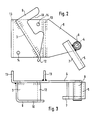
- the connecting element shown in FIGS. 1 to 3 has a bearing plate 6, to which an essentially flat contact plate 3 is fastened, for example by means of a welded connection.
- two mutually parallel holding plates 13 are formed on the bearing plate 6, for example by bending an end region of the bearing plate 6 and by welding a separate element.
- the two holding plates 13 are at a distance from one another which is dimensioned such that a first spar 1 of a first conductor element 1, not further shown in the figures, can be inserted into the U-shaped cross section formed by the printed circuit board 6 and the two holding plates 13.
- the contact plate 3 is inclined at an angle to the longitudinal axis of the first spar, the angle of inclination corresponding to the angle which the first spar 1 and a second spar 2 of a conductor element, not shown in detail to each other if these two ladder elements form a standing ladder.
- the bearing plate 6 shown in FIGS. 1 to 3 has a free end area on which a pivot plate 5 is pivotally mounted about an axis 4 arranged perpendicular to the longitudinal axis of the first spar.
- the swivel plate 5 is provided with a bearing block 8 which is attached to the swivel plate 5 above the center of gravity.
- This eccentric mounting causes that, as shown in Fig. 2, the pivot plate 5 assumes a position in the unloaded state with a vertical arrangement of the first spar, in which this either to the contact plate 3 or is substantially parallel to the longitudinal axis of the first spar 1. This arrangement serves to facilitate the introduction of the second spar 2.
- the bearing plate 5 is further provided with a first support leg 7 which extends essentially parallel to the bearing plate 6.
- the pivot plate 5 and the first support leg 7 thus form a rectangular cross section.
- the space formed between the bearing plate 6 and the first support leg 7 is dimensioned such that it is equal to the width of the second spar 2, so that the second spar 2 can be held in a tilt-proof manner relative to the first spar.
- the second support leg 9 also serves to better hold the second spar 2 of the second conductor element.
- the second support leg 9 has a recess 10 which is groove-like and is dimensioned such that it is adapted to the dimensions of a rung 11 connected to the second spar 2.
- the possibility of inserting the rung 11 into the recess 10 results in additional securing or locking of the second spar 2.
- the abutment plate 3 can be rounded at its lower end 12 in order to make it easier to insert the second bar 2 or to move the second bar 2 relative to the first bar 1.
- the bearing plate 6 can also be provided with recesses 14, through which screws or rivets can be carried out, by means of which the bearing plate 6 can be attached to the first spar 1.
- Fig. 1 the connecting element according to the invention is shown in an operational state.
- the bearing plate 6 is connected to the first spar 1 by means of rivets (not shown in detail) which are passed through the recesses 14, the two holding plates 13 being in contact with the first spar 1.
- the second spar 2 of the second conductor element is inserted between the contact plate 3 and the pivot plate 5 and subsequently pivoted so that it rests frictionally on the surface of the contact plate 3 and the pivot plate 5.
- the rung 11 was inserted into the recess 10 of the second support leg 9 to effect an additional locking. If the second spar 2 is to be arranged on the first spar 1 in such a way that there is no rung 11 in the region of the recess 10, then there is reliable jamming due to the friction between the contact plate 3 and the pivot plate 5.
- the first conductor element 1 is wider than the second conductor element 2, so that the latter can be moved or displaced with its spars in the region between the spars of the first conductor element.
- a connecting element is arranged on each spar of the first conductor element, the two connecting elements being constructed in mirror image of one another.
Abstract
Zur Verbindung zweier Leiterelemente (1, 2) ist ein Verbindungselement vorgesehen wobei die Klemmelemente eines an einem ersten Holm (1) befestigten Verbindungselementes in Form einer ebenen, zur Längsachse des ersten Holms (1) geneigten, mit dem Verbindungselement verbundenen Anlageplatte (3) und einer um eine senkrecht zur Längsachse des ersten Holms (1) angeordnete Achse (4) schwenkbaren Schwenkplatte (5) ausgebildet ist. Das Verbindungselement ist bei allen Arten von Mehrzweckleitern verwendbar.A connecting element is provided for connecting two conductor elements (1, 2), the clamping elements of a connecting element fastened to a first spar (1) in the form of a flat contact plate (3) and connected to the connecting element and inclined to the longitudinal axis of the first spar (1) a swivel plate (5) which is pivotable about an axis (4) arranged perpendicular to the longitudinal axis of the first spar (1) is formed. The connecting element can be used with all types of multi-purpose conductors.
Description
Die Erfindung bezieht sich auf ein Verbindungselement zur Verbindung eines ersten und eines zweiten Leiterelementes, wobei das Verbindungselement an einem ersten Holm des ersten Leiterelementes befestigt ist und Klemmelemente für einen zweiten Holm einer zweiten Leiter umfaßt.The invention relates to a connecting element for connecting a first and a second conductor element, the connecting element being fastened to a first spar of the first conductor element and comprising clamping elements for a second spar of a second conductor.
Es sind Leitern bekannt, welche ein erstes und ein zweites Leiterelement aufweisen, welche jeweils in Form von geraden Leitern mit zwei Holmen und einer entsprechenden Anzahl von Sprossen ausgebildet sind. Die beiden Leiterelemente sind üblicherweise an ihren oberen Endbereichen miteinander verbindbar, um eine selbststehende Leiter in Form einer Aufstelleiter auszubilden. Um einen sicheren Stand der Leiter zu gewährleisten ist es erforderlich, nicht nur die oberen Endbereiche der Leiterelemente in entsprechender Weise miteinander zu verbinden, sondern auch dafür Sorge zu tragen, daß die unteren Endbereiche, welche auf dem Boden aufgestellt sind, sich nicht unter Belastung voneinander entfernen, was zu einem Zusammenfallen der Aufstelleiter führen würde.Ladders are known which have a first and a second conductor element, which are each designed in the form of straight conductors with two bars and a corresponding number of rungs. The two ladder elements can usually be connected to one another at their upper end regions in order to form a self-standing ladder in the form of a standing ladder. In order to ensure that the ladder stands securely, it is necessary not only to connect the upper end regions of the conductor elements to one another in a corresponding manner, but also to ensure that the lower end regions, which are set up on the floor, do not separate from one another under load remove, which would cause the installation ladder to collapse.
Um das Auseinanderklappen oder Auseinanderbewegen der unteren Enden der beiden Leiterelemente zu verhindern, ist aus sicherungstechnischen Gründen, insbesondere bei Leiterelementen, welche in ihrem oberen Bereich durch ein Scharnier verbunden sind, vorgeschrieben, daß die unteren Bereiche der Leiterelemente mittels eines Zugbandes verbunden sind, welches die maximale Spreizung der Leiterelemente begrenzt. Die Verwendung eines Zugbandes erweist sich insbesondere bei Mehrzweckleitern, bei welchen die Leiterelemente auch in anderer Zuordnung zueinander verwendbar sind, als nachteilig, da das Zugband von der Bedienungsperson bei Verwendung der Leiterelemente in Form einer Aufstelleiter angebracht werden muß, wobei stets die Gefahr besteht, daß diese Sicherungsmaßnahme vergessen wird.To prevent the lower ends of the two conductor elements from unfolding or moving apart, is off For safety reasons, in particular in the case of conductor elements which are connected by a hinge in their upper region, it is prescribed that the lower regions of the conductor elements are connected by means of a tension band which limits the maximum spreading of the conductor elements. The use of a drawstring proves to be disadvantageous in particular in the case of multipurpose ladders, in which the ladder elements can also be used in a different association with one another, since the drawstring must be attached by the operator when using the ladder elements in the form of a set-up ladder, with the risk that this security measure is forgotten.
Bei einem bekannten Verbindungselement zur Verbindung zweier Leiterelemente werden die oberen Bereiche der Leiterelemente miteinander verklemmt. Diese Verklemmung kann bei den bekannten Verbindungselementen jedoch nicht eine weitere winkelmäßige Spreizung der Leiterelemente verhindern, da diese üblicherweise aus Aluminiumprofilen dünnen Querschnitts gefertigt sind und bei den bekannten Verbindungselementen Kräfte auftreten können, die zu einer Zerstörung oder Beschädigung der Aluminiumprofile führen können. Deshalb ist es auch bei diesen Ausgestaltungsformen aus Sicherheitsgründen erforderlich, ein Zugband zu verwenden. Das Zugband erweist sich auch dadurch als nachteilig, daß insbesondere eine Verschiebung der beiden Leiterelemente zueinander, sowie dies bei anderen Anwendungsfällen wünschenswert ist, nicht möglich ist, da das Zugband entweder den Verschiebeweg begrenzt oder von der Bedienungsperson gelöst werden muß, wodurch sich wiederum die bereits beschriebenen Sicherheitsprobleme ergeben.In a known connecting element for connecting two conductor elements, the upper regions of the conductor elements are clamped together. In the known connecting elements, however, this jamming cannot prevent a further angular spreading of the conductor elements, since these are usually made from aluminum profiles with a thin cross-section and forces can occur in the known connecting elements, which can lead to destruction or damage to the aluminum profiles. For this reason, it is also necessary to use a drawstring in this embodiment for safety reasons. The drawstring also proves to be disadvantageous in that a displacement of the two conductor elements relative to one another, as is desirable in other applications, is not possible, since the drawstring either limits the displacement path or has to be released by the operator, which in turn already eliminates the problem described security problems arise.
Der Erfindung liegt die Aufgabe zugrunde, ein Verbindungselement der Eingangs genannten Art zu schaffen, welches bei einfachem Aufbau und betriebssicherer Handhabbarkeit eine Verbindung zweier Leiterelemente so gestattet, daß auf ein Zugband verzichtet werden kann und wobei die relative Beweglichkeit der beiden Leiterelemente hinsichtlich anderer Anordnungsvarianten nicht behindert wird.The invention has for its object to provide a connecting element of the type mentioned, which at simple construction and reliable handling allows a connection of two conductor elements in such a way that a tension band can be dispensed with and the relative mobility of the two conductor elements with respect to other arrangement variants is not impeded.
Die Aufgabe wird erfindungsgemäß dadurch gelöst, daß die Klemmelemente in Form einer ebenen, zur Längsachse des ersten Holms geneigten, mit dem Verbindungselement verbundenen Anlageplatte und einer um eine senkrecht zur Längsachse des ersten Holmes angeordneten Achse schwenkbaren Schwenkplatte ausgebildet sind.The object is achieved in that the clamping elements are in the form of a flat, inclined to the longitudinal axis of the first spar, connected to the connecting element and a pivotable about an axis arranged perpendicular to the longitudinal axis of the first spar pivot plate.
Das erfindungsgemäße Verbindungselement zeichnet sich durch eine Reihe erheblicher Vorteile aus. Durch die Verwendung einer Klemmplatte und einer Schwenkplatte ist es möglich, eine große Anlagefläche für den zweiten Holm zu schaffen, so daß eine Beschädigung des zweiten Holmes, insbesondere durch eine Anlage an einer Kante des Verbindungselementes vermieden werden kann. Durch die Anlageplatte und die Schwenkplatte ist es erfindungsgemäß möglich, den zweiten Holm reibschlüssig zu halten, wobei die Reibungskraft bei Belastung einer durch die beiden Leiterelemente gebildeten Aufstelleiter erhöht wird, so daß eine weitere winkelmäßige Spreizung der beiden Leiterelemente ausgeschlossen ist. Da erfindungsgemäß das Verbindungselement an dem ersten Holm des ersten Leiterelementes festangebracht ist, ist es auf besonders einfache Weise möglich, die beiden Leiterelemente zur Ausbildung einer Aufstelleiter miteinander zu verbinden.The connecting element according to the invention is characterized by a number of considerable advantages. By using a clamping plate and a swivel plate, it is possible to create a large contact surface for the second spar, so that damage to the second spar, in particular by contacting an edge of the connecting element, can be avoided. Due to the contact plate and the swivel plate, it is possible according to the invention to hold the second spar in a frictional manner, the frictional force being increased when a set-up ladder formed by the two conductor elements is loaded, so that a further angular spread of the two conductor elements is excluded. Since, according to the invention, the connecting element is fixedly attached to the first spar of the first conductor element, it is possible in a particularly simple manner to connect the two conductor elements to one another to form a set-up ladder.
Da erfindungsgemäß die Anlageplatte in einem Winkel zur Längsachse des ersten Holmes geneigt ist, läßt sich auf diese Weise der bei Ausformung der Aufstelleiter zwischen den beiden Leiterelementen gebildete Winkel auf besonders einfache Weise festlegen.Since, according to the invention, the abutment plate is inclined at an angle to the longitudinal axis of the first spar, it is possible in this way to provide the intermediate ladder when the upright is formed set the two conductor elements formed angles in a particularly simple manner.
Durch die schwenkbare Anordnung der Schwenkplatte wird ein Verkanten des zweiten Holms relativ zu dem Verbindungselement ausgeschlossen, da sich die Schwenkplatte stets vollständig gegen die entsprechende Fläche des Holmes anlegen kann.Due to the pivotable arrangement of the pivot plate, tilting of the second spar relative to the connecting element is excluded, since the pivot plate can always lie completely against the corresponding surface of the spar.
In einer günstigen Weiterbildung der Erfindung sind die Anlageplatte und die Schwenkplatte an einer an dem ersten Holm befestigten Lagerplatte angebracht. Die Lagerplatte kann entweder entfernbar an dem ersten Holm befestigt sein, es ist auch möglich, diese in nicht lösbarer Weise mit dem ersten Holm zu verbinden. Durch die Verwendung einer zusätzlichen Lagerplatte ist es möglich, einen ausreichenden Platz zum Anordnen des ersten Holmes bzw. zum Einführen des ersten Holmes zwischen die Anlageplatte und die Schwenkplatte zu schaffen.In a favorable development of the invention, the contact plate and the swivel plate are attached to a bearing plate attached to the first spar. The bearing plate can either be removably attached to the first spar, it is also possible to connect it to the first spar in a non-detachable manner. By using an additional bearing plate, it is possible to create sufficient space for arranging the first spar or for inserting the first spar between the contact plate and the swivel plate.
Um zu Verhindern, daß der Holm unter ungünstigen Belastungsbedingungen von der Lagerplatte bzw. von der Schwenkplatte abrutscht, kann in einer weiteren vorteilhaften Ausgestaltung der Erfindung vorgesehen sein, daß die Schwenkplatte zum Umgreifen des zweiten Holms auf der der Lagerplatte abgewandten Seite mit einem sich parallel zur Lagerplatte erstreckenden ersten Stützschenkel versehen ist. Bei dieser Ausgestaltung wird der zweite Holm von drei Seiten umgriffen, nämlich von der Lagerplatte, der Schwenkplatte und dem Stützschenkel. Die Verbindung der beiden Leiterelemente erfolgt dabei so, daß auch seitliche Verschiebungen der Aufstelleiter bzw. ein seitliches Wackeln in wirkungsvoller Weise unterbunden werden können.In order to prevent the spar from slipping under unfavorable load conditions from the bearing plate or from the pivot plate, it can be provided in a further advantageous embodiment of the invention that the pivot plate for gripping the second spar on the side facing away from the bearing plate with a parallel to Bearing plate extending first support leg is provided. In this embodiment, the second spar is encompassed from three sides, namely by the bearing plate, the swivel plate and the support leg. The connection of the two conductor elements takes place in such a way that lateral displacements of the erection ladder or lateral wobbling can be effectively prevented.
Zu einer sicheren Führung und Halterung des zweiten Holms kann es sich weiterhin als günstig erweisen, daß die Schwenkplatte eine Breite aufweist, welche gleich der Breite des zweiten Holms ist. Durch diese Maßnahme kann eine gewisse Klemmung des zweiten Holmes erfolgen, durch welche es möglich ist, die durch die beiden Leiterelemente gebildete Aufstelleiter zu versetzen oder zu tragen, ohne daß diese zusammenklappt.For safe guidance and mounting of the second spar, it can furthermore prove to be favorable that the swivel plate has a width which is equal to the width of the second spar. This measure allows the second spar to be clamped to a certain extent, by means of which it is possible to displace or carry the erection ladder formed by the two ladder elements without them collapsing.
Weiterhin kann es sich als günstig erweisen, wenn die Schwenkplatte mittels eines Lagerbockes oberhalb ihres Schwerpunktes an der der Anlageplatte abgewandten Seite an der Lagerplatte gelagert ist. Bei dieser Ausgestaltungsform beeinflußt zum einen die Lagerung der Schwenkplatte nicht deren Klemmwirkung, da der Lagerbock an der Rückseite der Schwenkplatte angeordnet ist. Durch die Lagerung oberhalb des Schwerpunktes der Schwenkplatte wird erreicht, daß bei einer vertikalen Anordnung des ersten Leiterelementes die Schwenkplatte im wesentlichen parallel zur Längsachse des ersten Holmes angeordnet ist, so daß eine Einführung oder Verschiebung des zweiten Holmes vorgenommen werden kann, ohne daß die Gefahr von ungewollten Klemmwirkungen eintritt.Furthermore, it can prove to be advantageous if the swivel plate is mounted on the bearing plate above its center of gravity on the side facing away from the contact plate by means of a bearing block. In this embodiment, on the one hand, the mounting of the swivel plate does not affect its clamping effect, since the bearing block is arranged on the back of the swivel plate. By mounting above the center of gravity of the swivel plate it is achieved that in a vertical arrangement of the first conductor element, the swivel plate is arranged substantially parallel to the longitudinal axis of the first spar, so that an introduction or displacement of the second spar can be carried out without the risk of unwanted clamping effects occur.
Die Anlageplatte kann einen sich parallel zu der Lagerplatte und in Richtung auf die Schwenkplatte erstreckenden zweiten Stützschenkel umfassen, welcher, ebenso wie der erste Stützschenkel zu einer Umgreifung des zweiten Holms dienen kann, um ein seitliches Wackeln der Aufstelleiter zu verhindern. Dabei kann es sich weiterhin als günstig erweisen, wenn in dem zweiten Stützschenkel eine nutartige Ausnehmung zur Einführung einer Sprosse des Leiterelementes vorgesehen ist. Durch diese Ausnehmung wird ein formschlüssiges Ergreifen der Sprosse ermöglicht, so daß eine zusätzliche Verankerung des zweiten Leiterelementes geschaffen wird. Durch diese Maßnahme läßt sich die Betriebssicherheit wesentlich erhöhen.The contact plate can comprise a second support leg extending parallel to the bearing plate and in the direction of the swivel plate, which, like the first support leg, can serve to encompass the second spar in order to prevent the erecting ladder from wobbling sideways. It can furthermore prove to be advantageous if a groove-like recess for introducing a rung of the ladder element is provided in the second support leg. This recess enables the rung to be gripped positively, so that an additional anchoring of the second conductor element is created. Through this Measure can significantly increase operational safety.
Da üblicherweise die Sprossen mit einer Spreizung in Ausnehmungen der Holme eingeführt sind, kann es sich als günstig erweisen, wenn die Anlageplatte zwischen der Lagerplatte und dem zweiten Stützschenkel eine Breite aufweist, die größer ist, als die Breite des zweiten Holmes, da zum einen die nutartige Ausnehmung in dem zweiten Stützschenkel genau an die Abmessungen der Sprosse anpaßbar sind und da zum anderen ein unbeabsichtigtes Verklemmen durch die Spreizung der Sprossen verhindert wird. Bei dieser Ausgestaltungsform liegt somit nicht der Holm, sondern die Spreizung der Sprossen flächig an dem zweiten Stützschenkel an.Since the rungs are usually inserted with a spread in recesses in the spars, it can prove to be advantageous if the contact plate between the bearing plate and the second support leg has a width which is greater than the width of the second spar, since on the one hand the groove-like recess in the second support leg can be adapted exactly to the dimensions of the rung and since, on the other hand, unintentional jamming is prevented by the spreading of the rungs. In this embodiment, it is not the spar but the spreading of the rungs that lies flat against the second support leg.
Weiterhin kann es sich als günstig erweisen, die Achse der Schwenkplatte am unteren Endbereich der Lagerplatte anzuordnen und die Anlageplatte so auszubilden, daß diese am unteren Endbereich der Lagerplatte endet. Diese Ausgestaltungsform erleichtert wesentlich das Einführen des zweiten Holms in das Befestigungselement und schafft die Möglichkeit, die reibschlüssige Klemmung so vorzunehmen, daß trotz der geringen Abmessungen des Verbindungselementes relativ große Hebelarme vorliegen.Furthermore, it can prove to be advantageous to arrange the axis of the swivel plate at the lower end region of the bearing plate and to design the contact plate so that it ends at the lower end region of the bearing plate. This embodiment significantly facilitates the insertion of the second spar into the fastening element and creates the possibility of performing the frictional clamping in such a way that, despite the small dimensions of the connecting element, there are relatively large lever arms.
Um die Einführung des zweiten Holmes zu erleichtern und um bei einer Parallelverschiebung der beiden Leiterelemente ein Verklemmen zu verhindern, kann das untere Ende der Anlageplatte abgerundet sein.In order to facilitate the introduction of the second spar and to prevent jamming when the two conductor elements are moved in parallel, the lower end of the contact plate can be rounded.
Die Lagerplatte wird bevorzugterweise mit zwei zueinander parallelen Halteplatten versehen sein, welche sich auf der der Anlageplatte und der Schwenkplatte abgewandten Seite der Lagerplatte erstrecken, so daß durch die Halteplatten und die Lagerplatte ein U-förmiger Querschnitt ausgebildet wird, welcher formschlüssig den ersten Holm umgreifen kann. Durch diese Maßnahme läßt sich die Befestigung der Lagerplatte und damit das Verbindungselement an dem ersten Holm wesentlich vereinfachen und stabiler ausgestalten.The bearing plate will preferably be provided with two mutually parallel holding plates, which extend on the side of the bearing plate facing away from the contact plate and the swivel plate, so that through the holding plates and the bearing plate has a U-shaped cross section, which can engage in a form-fitting manner around the first spar. This measure allows the mounting of the bearing plate and thus the connecting element on the first spar to be simplified and made more stable.
Um eine sichere Zuordnung des ersten und des zweiten Leiterelementes sicherzustellen, ist es vorteilhaft, wenn an jedem Holm des ersten Leiterelementes ein Verbindungselement angeordnet ist. Die Verbindungselemente sind dabei bevorzugterweise spiegelbildlich ausgebildet, so daß es möglich ist, das erste Leiterelement breiter als das zweite Leiterelement auszubilden.In order to ensure a reliable assignment of the first and second conductor elements, it is advantageous if a connecting element is arranged on each spar of the first conductor element. The connecting elements are preferably mirror images, so that it is possible to make the first conductor element wider than the second conductor element.
Erfindungsgemäß ist durch das Verbindungselement die Möglichkeit geschaffen, das erste Leiterelement und das zweite Leiterelement stufenlos zueinander zur Ausbildung einer Aufstelleiter zu verbinden, insbesondere ist es möglich, die Aufstelleiter so auszubilden, daß diese auch auf Treppen oder Absätzen oder auch auf abhängigem Gelände aufgestellt werden kann.According to the invention, the connecting element makes it possible to connect the first conductor element and the second conductor element to one another in a stepless manner to form a set-up ladder, in particular it is possible to design the set-up ladder in such a way that it can also be set up on stairs or shoulders or on dependent terrain .
Im folgenden wird die Erfindung anhand eines Ausführungsbeispiels in Verbindung mit der Zeichnung beschrieben. Dabei zeigt:
- Fig. 1 eine perspektivische Darstellung eines Ausführungsbeispieles des erfindungsgemäßen Verbindungselementes und von Teilen zugeordneter Leiterelemente
- Fig. 2 eine Seitenansicht des in Fig. 1 gezeigten Verbindungselementes und
- Fig. 3 eine Draufsicht auf das in Fig. 2 gezeigte Verbindungselement.
- Fig. 1 is a perspective view of an embodiment of the connecting element according to the invention and parts of associated conductor elements
- Fig. 2 is a side view of the connecting element shown in Fig. 1 and
- Fig. 3 is a plan view of the connecting element shown in Fig. 2.
Das in den Figuren 1 bis 3 gezeigte Verbindungselement weist eine Lagerplatte 6 auf, an welcher eine im wesentlichen ebene Anlageplatte 3 befestigt ist, beispielsweise mittels einer Schweißverbindung.The connecting element shown in FIGS. 1 to 3 has a
An der der Anlageplatte 3 abgewandten Seite sind an der Lagerplatte 6 zwei zueinander parallele Halteplatten 13 ausgebildet, beispielsweise durch Umbiegung eines Endbereiches der Lagerplatte 6 und durch Anschweißen eines seperaten Elementes. Die beiden Halteplatten 13 weisen zueinander einen Abstand auf, welcher so bemessen ist, daß ein erster Holm 1 eines ersten, in den Figuren weiter nicht dargestellten Leiterelementes 1 in den durch die Leiterplatte 6 und die beiden Halteplatten 13 ausgebildeten U-förmigen Querschnitt einführbar ist.On the side facing away from the
Die Anlageplatte 3 ist, wie insbesondere aus den Fig. 1 und 2 ersichtlich ist, in einem Winkel zur Längsachse des ersten Holms geneigt, wobei der Neigungswinkel dem Winkel entspricht, welchen der erste Holm 1 und ein zweiter Holm 2 eines im einzelnen nicht dargestellten Leiterelementes zueinaner aufweisen, wenn diese beiden Leiterelemente eine Aufstelleiter bilden.1 and 2, the
Die in den Fig. 1 bis 3 gezeigte Lagerplatte 6 weist einen freien Endbereich auf, an welchem um eine senkrecht zur Längsachse des ersten Holms angeordnete Achse 4 eine Schwenkplatte 5 schwenkbar gelagert ist. Die Schwenkplatte 5 ist mit einem Lagerbock 8 versehen, welcher oberhalb des Schwerpunktes der Schwenkplatte 5 an dieser befestigt ist. Diese außermittige Lagerung bewirkt, daß, wie in Fig. 2 dargestellt, die Schwenkplatte 5 im nicht belasteten Zustand bei vertikaler Anordnung des ersten Holms eine Stellung einnimmt, in welcher dieser entweder zu der Anlageplatte 3 oder zur Längsachse des ersten Holms 1 im wesentlichen parallel ist. Diese Anordnung dient zur Erleichterung der Einführung des zweiten Holms 2.The
Die Lagerplatte 5 ist weiterhin mit einem ersten Stützschenkel 7 versehen, welcher sich im wesentlichen parallel zu der Lagerplatte 6 erstreckt. Die Schwenkplatte 5 und der erste Stützschenkel 7 bilden somit einen rechtwinkeligen Querschnitt. Der zwischen der Lagerplatte 6 und dem ersten Stützschenkel 7 ausgebildete Raum ist so bemessen, daß er zur Breite des zweiten Holms 2 gleich ist, so daß der zweite Holm 2 in kippsicherer Weise relativ zu dem ersten Holm gehalten werden kann.The bearing plate 5 is further provided with a
An dem freien Ende der Lagerplatte 3 ist diese mit einem zweiten Stützschenkel 9 verbunden, welcher sich ebenfalls im wesentlichen parallel zu der Lagerplatte 6 erstreckt. Auch der zweite Stützschenkel 9 dient zur besseren Halterung des zweiten Holms 2 des zweiten Leiterelements.At the free end of the
Wie insbesondere aus den Fig. 1 und 2 ersichtlich, weist der zweite Stützschenkel 9 eine Ausnehmung 10 auf, welche nutartig ausgebildet ist und so dimensioniert ist, daß diese an die Abmessungen einer mit dem zweiten Holm 2 verbundenen Sprosse 11 angepaßt ist. Durch die Möglichkeit, die Sprosse 11 in die Ausnehmung 10 einzuführen, wird eine zusätzliche Sicherung oder Verriegelung des zweiten Holms 2 erreicht.As can be seen in particular from FIGS. 1 and 2, the
Die Anlageplatte 3 kann an ihrem unteren Ende 12 abgerundet sein, um ein Einschieben des zweiten Holms 2 bzw. ein Verschieben des zweiten Holms 2 relativ zu dem ersten Holm 1 zu erleichtern.The
Die Lagerplatte 6 kann weiterhin mit Ausnehmungen 14 versehen sein, durch welche Schrauben oder Nieten durchführbar sind, mittels derer die Lagerplatte 6 an den ersten Holm 1 befestigt werden kann.The bearing
In Fig. 1 ist das erfindungsgemäße Verbindungselement in einem betriebsbereiten Zustand dargestellt. Dabei ist die Lagerplatte 6 über im einzelnen nicht gezeigte Nieten, welche durch die Ausnehmungen 14 durchgeführt sind, mit dem ersten Holm 1 verbunden, wobei sich die beiden Halteplatten 13 in Anlage an dem ersten Holm 1 befinden. Der zweite Holm 2 des zweiten Leiterelementes ist zwischen die Anlageplatte 3 und die Schwenkplatte 5 eingeschoben und nachfolgend so verschwenkt worden, daß dieser reibschlüssig an der Fläche der Anlageplatte 3 und der Schwenkplatte 5 anliegt. Zusätzlich wurde die Sprosse 11 in die Ausnehmung 10 des zweiten Stützschenkels 9 eingeführt, um eine zusätzliche Verriegelung zu bewirken. Wenn der zweite Holm 2 so an dem ersten Holm 1 angeordnet werden soll, daß keine Sprosse 11 im Bereich der Ausnehmung 10 vorhanden ist, so erfolgt eine sichere Verklemmung durch die Reibung zwischen der Anlageplatte 3 und der Schwenkplatte 5.In Fig. 1, the connecting element according to the invention is shown in an operational state. The bearing
Bei dem gezeigten Ausführungsbeispiel ist das erste Leiterelement 1 breiter ausgebildet, als das zweite Leiterelement 2, so daß letzteres mit seinen Holmen im Bereich zwischen den Holmen des ersten Leiterelementes bewegbar oder verschiebbar ist. Um eine stabile Lagerung der beiden Leiterelemente aneinander zu gewährleisten, ist an jedem Holm des ersten Leiterelementes ein Verbindungselement angeordnet, wobei die beiden Verbindungselemente spiegelbildlich zueinander aufgebaut sind.In the exemplary embodiment shown, the first conductor element 1 is wider than the second conductor element 2, so that the latter can be moved or displaced with its spars in the region between the spars of the first conductor element. In order to ensure a stable mounting of the two conductor elements on one another, a connecting element is arranged on each spar of the first conductor element, the two connecting elements being constructed in mirror image of one another.
Die Erfindung ist nicht auf das gezeigte Ausführungsbeispiel beschränkt, vielmehr ergeben sich für den Fachmann im Rahmen der Erfindung vielfältige Abwandlungsmöglichkeiten.The invention is not limited to the exemplary embodiment shown, rather there are various possible modifications for the person skilled in the art within the scope of the invention.
Claims (13)
Applications Claiming Priority (2)
| Application Number | Priority Date | Filing Date | Title |
|---|---|---|---|
| DE8811069U | 1988-09-01 | ||
| DE8811069U DE8811069U1 (en) | 1988-09-01 | 1988-09-01 |
Publications (1)
| Publication Number | Publication Date |
|---|---|
| EP0359046A1 true EP0359046A1 (en) | 1990-03-21 |
Family
ID=6827481
Family Applications (1)
| Application Number | Title | Priority Date | Filing Date |
|---|---|---|---|
| EP89116080A Withdrawn EP0359046A1 (en) | 1988-09-01 | 1989-08-31 | Connecting element |
Country Status (3)
| Country | Link |
|---|---|
| US (1) | US4947960A (en) |
| EP (1) | EP0359046A1 (en) |
| DE (1) | DE8811069U1 (en) |
Cited By (1)
| Publication number | Priority date | Publication date | Assignee | Title |
|---|---|---|---|---|
| US6476250B1 (en) | 1999-11-17 | 2002-11-05 | Japan Science And Technology Corporation | Optically active fluorinated binaphthol derivative |
Families Citing this family (2)
| Publication number | Priority date | Publication date | Assignee | Title |
|---|---|---|---|---|
| US5638918A (en) * | 1995-07-18 | 1997-06-17 | Hebda; Dorothy E. | Ladder conversion kit |
| FR2898381B1 (en) * | 2006-03-10 | 2009-10-02 | Macc Sa | JOINT HEADS FOR TRANSFORMABLE LADDERS |
Citations (5)
| Publication number | Priority date | Publication date | Assignee | Title |
|---|---|---|---|---|
| US2223911A (en) * | 1939-03-06 | 1940-12-03 | James L Garnette | Stepladder |
| FR1166010A (en) * | 1957-01-15 | 1958-11-03 | transformable ladder | |
| FR1372452A (en) * | 1963-04-17 | 1964-09-18 | Ladder fittings | |
| FR2150013A5 (en) * | 1971-08-12 | 1973-03-30 | Hymer Leichtmetallbau | |
| FR2391349A1 (en) * | 1977-05-16 | 1978-12-15 | Mullca | Multipurpose extending ladder hinge - has half-open components with notches to receive rungs of narrower section |
Family Cites Families (3)
| Publication number | Priority date | Publication date | Assignee | Title |
|---|---|---|---|---|
| US766246A (en) * | 1904-04-06 | 1904-08-02 | Aaron Hartzler | Step and extension ladder. |
| US2873903A (en) * | 1958-06-30 | 1959-02-17 | Chesebro Whitman Mfg Corp | Convertible ladders |
| FR2326566A1 (en) * | 1975-10-03 | 1977-04-29 | Gubri Sa Ets L | Convertible step or extending ladder - has strut tops fitted with sleeve and pin for hinging ladder in limiting bracket |
-
1988
- 1988-09-01 DE DE8811069U patent/DE8811069U1/de not_active Expired
-
1989
- 1989-08-30 US US07/400,556 patent/US4947960A/en not_active Expired - Fee Related
- 1989-08-31 EP EP89116080A patent/EP0359046A1/en not_active Withdrawn
Patent Citations (5)
| Publication number | Priority date | Publication date | Assignee | Title |
|---|---|---|---|---|
| US2223911A (en) * | 1939-03-06 | 1940-12-03 | James L Garnette | Stepladder |
| FR1166010A (en) * | 1957-01-15 | 1958-11-03 | transformable ladder | |
| FR1372452A (en) * | 1963-04-17 | 1964-09-18 | Ladder fittings | |
| FR2150013A5 (en) * | 1971-08-12 | 1973-03-30 | Hymer Leichtmetallbau | |
| FR2391349A1 (en) * | 1977-05-16 | 1978-12-15 | Mullca | Multipurpose extending ladder hinge - has half-open components with notches to receive rungs of narrower section |
Cited By (1)
| Publication number | Priority date | Publication date | Assignee | Title |
|---|---|---|---|---|
| US6476250B1 (en) | 1999-11-17 | 2002-11-05 | Japan Science And Technology Corporation | Optically active fluorinated binaphthol derivative |
Also Published As
| Publication number | Publication date |
|---|---|
| DE8811069U1 (en) | 1988-11-10 |
| US4947960A (en) | 1990-08-14 |
Similar Documents
| Publication | Publication Date | Title |
|---|---|---|
| EP0425786B1 (en) | Ladder | |
| WO2000009850A1 (en) | Anti-slip device for ladders | |
| DE1812628A1 (en) | Multipart ladder | |
| EP0033475B2 (en) | Double ladder | |
| DE2633357A1 (en) | COLLAPSIBLE STAND | |
| EP0360049B1 (en) | Ladder platform | |
| DE2804152A1 (en) | GUIDE RAIL FOR A SAFETY DEVICE THAT CAN BE USED WHEN CLIMBING A LADDER | |
| EP0580960A1 (en) | Ladder platform | |
| EP0419914A1 (en) | Foot for ladder rungs | |
| DE19811368C2 (en) | Fastening element for ladder supports | |
| EP0359046A1 (en) | Connecting element | |
| DE2942220C2 (en) | Securing against spreading of a stepladder | |
| DE19527944C2 (en) | Scaffold holder for step ladders or the like | |
| DE3327025A1 (en) | Double ladder | |
| EP0355504A1 (en) | Wall spacer for a ladder | |
| DE3505917C2 (en) | ||
| EP3348780B1 (en) | Ladder connector and assembly comprising same | |
| DE2649430B2 (en) | Folding ladder | |
| EP3431700B1 (en) | Stabilizing device for ladders | |
| DE19505281C2 (en) | conductor arrangement | |
| WO2017207137A1 (en) | Detatchable rail profiles for use with climbing aids | |
| DE10244277C1 (en) | Device for adjusting the leg spread of a wooden tripod has a barrier element arranged on the outwardly directed side surfaces of a profile side and consisting of a slide and a slide guide | |
| DE19819654A1 (en) | Ladder with anti-slip safety fitting | |
| DE3104981A1 (en) | Step-ladder | |
| DE19527235C2 (en) | Stage truss |
Legal Events
| Date | Code | Title | Description |
|---|---|---|---|
| PUAI | Public reference made under article 153(3) epc to a published international application that has entered the european phase |
Free format text: ORIGINAL CODE: 0009012 |
|
| AK | Designated contracting states |
Kind code of ref document: A1 Designated state(s): AT BE CH DE ES FR GB GR IT LI LU NL SE |
|
| 17P | Request for examination filed |
Effective date: 19900426 |
|
| 17Q | First examination report despatched |
Effective date: 19910529 |
|
| STAA | Information on the status of an ep patent application or granted ep patent |
Free format text: STATUS: THE APPLICATION HAS BEEN WITHDRAWN |
|
| 18W | Application withdrawn |
Withdrawal date: 19910913 |