EP0359019A2 - Spurregelkreis für ein magnetisches Bandgerät mit Schraubenlinienabtastung - Google Patents
Spurregelkreis für ein magnetisches Bandgerät mit Schraubenlinienabtastung Download PDFInfo
- Publication number
- EP0359019A2 EP0359019A2 EP89115859A EP89115859A EP0359019A2 EP 0359019 A2 EP0359019 A2 EP 0359019A2 EP 89115859 A EP89115859 A EP 89115859A EP 89115859 A EP89115859 A EP 89115859A EP 0359019 A2 EP0359019 A2 EP 0359019A2
- Authority
- EP
- European Patent Office
- Prior art keywords
- signal
- reproduced
- signals
- pilot
- track
- Prior art date
- Legal status (The legal status is an assumption and is not a legal conclusion. Google has not performed a legal analysis and makes no representation as to the accuracy of the status listed.)
- Granted
Links
Images


Classifications
-
- G—PHYSICS
- G11—INFORMATION STORAGE
- G11B—INFORMATION STORAGE BASED ON RELATIVE MOVEMENT BETWEEN RECORD CARRIER AND TRANSDUCER
- G11B5/00—Recording by magnetisation or demagnetisation of a record carrier; Reproducing by magnetic means; Record carriers therefor
- G11B5/48—Disposition or mounting of heads or head supports relative to record carriers ; arrangements of heads, e.g. for scanning the record carrier to increase the relative speed
- G11B5/58—Disposition or mounting of heads or head supports relative to record carriers ; arrangements of heads, e.g. for scanning the record carrier to increase the relative speed with provision for moving the head for the purpose of maintaining alignment of the head relative to the record carrier during transducing operation, e.g. to compensate for surface irregularities of the latter or for track following
-
- G—PHYSICS
- G11—INFORMATION STORAGE
- G11B—INFORMATION STORAGE BASED ON RELATIVE MOVEMENT BETWEEN RECORD CARRIER AND TRANSDUCER
- G11B15/00—Driving, starting or stopping record carriers of filamentary or web form; Driving both such record carriers and heads; Guiding such record carriers or containers therefor; Control thereof; Control of operating function
- G11B15/18—Driving; Starting; Stopping; Arrangements for control or regulation thereof
- G11B15/46—Controlling, regulating, or indicating speed
- G11B15/467—Controlling, regulating, or indicating speed in arrangements for recording or reproducing wherein both record carriers and heads are driven
- G11B15/4673—Controlling, regulating, or indicating speed in arrangements for recording or reproducing wherein both record carriers and heads are driven by controlling the speed of the tape while the head is rotating
- G11B15/4675—Controlling, regulating, or indicating speed in arrangements for recording or reproducing wherein both record carriers and heads are driven by controlling the speed of the tape while the head is rotating with provision for information tracking
- G11B15/4676—Controlling, regulating, or indicating speed in arrangements for recording or reproducing wherein both record carriers and heads are driven by controlling the speed of the tape while the head is rotating with provision for information tracking using signals recorded in tracks disposed in parallel with the scanning direction
- G11B15/4677—Controlling, regulating, or indicating speed in arrangements for recording or reproducing wherein both record carriers and heads are driven by controlling the speed of the tape while the head is rotating with provision for information tracking using signals recorded in tracks disposed in parallel with the scanning direction using auxiliary signals, i.e. pilot signals
- G11B15/4678—Controlling, regulating, or indicating speed in arrangements for recording or reproducing wherein both record carriers and heads are driven by controlling the speed of the tape while the head is rotating with provision for information tracking using signals recorded in tracks disposed in parallel with the scanning direction using auxiliary signals, i.e. pilot signals superimposed on the main signal track
Definitions
- the present invention relates generally to a tracking control circuit of a magnetic tape reproducing apparatus having a rotary head for helical scanning, and more particularly to a tracking control circuit in a digital audio tape reproducing apparatus having the rotary head for helical scanning.
- a digital recording and reproducing, system utilizing a pulse code modulation technology have been introduced into an audio apparatus in order to improve high-fidelity characteristic in reproduction of music or sound.
- a digital audio tape recorder one of the digital audio apparatus, comprises plural magnetic heads mounted on a rotary member placed in a rotary cylinder on which a magnetic tape is wound and is transported thereby, and the magnetic heads run on the magnetic tape in the direction which is oblique with respect to the direction along the length of the magnetic tape.
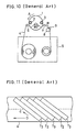
- FIG. 10 is a plan view of an example of a conventional magnetic tape transporting mechanism.
- a rotary cylinder 1 rotates in the direction of arrow A.
- the magnetic tape 4 which is drawn from a cassette 5 is wound around the peripheral region of about 90° of central angle of the rotary cylinder 1 by mean of two guide pins 6 and 7, and is transported in the direction of arrow B by a driving capstan 9 and a pinch roller 8.
- Two magnetic heads 2 and 3 mounted on a rotary head holder are arranged at the periphery of the rotary cylinder 1 so that each head tip slightly protrudes from the peripheral surface of the cylinder 1.
- FIG. 11 is a plan view of the magnetic tape 4 showing recorded tracks.
- the tracks are inclined, as shown by an arrow C, relative to the transporting direction D of the magnetic tape 4.
- tracks T2 are formed by the magnetic head 2 and tracks T3 are formed by the magnetic head 3.
- tracking servo means is provided in the transporting device of the magnetic tape 4.
- An automatic track finding method (abbreviated in general as ATF) is employed for the tracking servo means.
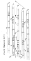
- a predetermined ATF signal is recorded on a start region and an end region of each track. Allocation of the ATF signal in the normal track mode is illustrated by FIG. 12.
- the ATF signal composed of a pilot signal P and a synchronizing signal S which are lower than the digitalized signal of data in frequency.
- the allocation pattern of the ATF signal is standardized and is repeated every four tracks on the magnetic tape 4.
- the magnetic head 2 traces the track T2 in the direction of arrow E and detects early pilot signals P A , P B and P C and the synchronizing signal 5.
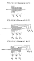
- a signal as shown by FIG.13(a), FIG.13(b) or FIG.13(c) is obtained by amplifying the detected signal of the pilot signal P A , P B or P C with an amplifier and then passing it through a low-pass filter.
- FIG.13(a) When the magnetic head 2 accurately traces the track T2, a signal shown by FIG.13(a) is output.
- the wave form P a shows the detected signal of the pilot signal P A
- the waveforms P b and P c show the crosstalks of the pilot signals P B and P C , respectively. Since the center C H of the magnetic head 2 is on the center line C L of the track T2, the output level P1 of the wave form P b equal to that of the wave form P c .
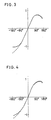
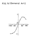
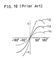
- FIG. 14 represents a level of a tracking error signal versus the deflected value represented by angle.
- a deflected angle of the abscissa is zero degree.
- the deflected angle is +180° or -180°. Then, the ordinate designates the level of the tracking error signal corresponding to the difference between the levels P1 and P2.
- the levels P1 or P2 of the pilot signals P B and P C are detected in synchronism with synchronizing signals SP1 and SP2, respectively.
- the synchronizing signals SP1 and SP2 are created on the basis of the synchronizing signal S of the ATF signal.
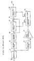
- FIG. 15 is a block diagram of a tracking control circuit for creating the tracking error signal in the prior art.
- the detected signal of the magnetic head 2 or 3 is amplified by an amplifier 11 and is applied to a low-pass filter 15.
- the higher frequency component including digitalized signal of data and the synchronizing signal S is eliminated by the low-pass filter 15.
- the output signal of the low-pass filter 15 is applied to an envelope detecting circuit 16, and envelopes of the pilot signals P A , P B and P C are detected.
- the amplified synchronizing signal S is separated from other signals by a band-pass filter 12, and then the zero level of the synchronizing signal S is detected by a zero-cross comparator 13.
- a synchronizing signal generator 14 generates the synchronizing signals SP1 and SP2 on the basis of the output of the zero cross comparator 13.
- the synchronizing signal SP1 applied to a sample-hold circuit 17 and the level P1 of the pilot signal P B is detected.
- the value of the level P2 subtracted from the value of the level P1 at an adder 18, and a resultant value is held by a sample-hold circuit 19 in synchronism with the synchronizing signal SP2.
- the resultant value is the value of the tracking error signal.
- the tracking error signal is applied to a tracking servo means which is generally understood to one with ordinary skill in the art and therefore is omitted in the description.
- a characteristic of the level of the tracking error signal seriously deviates from a normal characteristic shown by a solid line L2 in FIG. 16 due to unbalance between sensitivities of the respective magnetic heads 2 and 3 or variation of characteristic of a magnetic tape.
- Various deviated characteristics of the level of the tracking error signal are represented by a dashed line L1 or an alternate long and short dash line L3. Consequently, a tracking servo loop gain must be varied to meet the deviation, and hence stable servo operation can not be maintained.
- an automatic gain control circuit 21 (hereinafter abbreviated as AGC circuit) is provided between the amplifier 11 and the low pass filter 15. Moreover, an adder 22 for calculating a sum of the levels P1, P2 and P3 in synchronism with the synchronizing signals SP1, SP2 and SP3 is provided, and the output signal of the adder 22 is applied to the AGC circuit 21.
- the synchronizing signal SP3 is created on the basis of the reproduced signal of a synchronizing signal S of a neighboring tack.
- the gain of the AGC circuit 21 is controlled by the output signal of the adder 22, and fluctuation of the output of the magnetic heads 2 and 3 is compensated the characteristic of the level of the tracking error signal shown by the solid line L2 of FIG. 16 can be maintained.
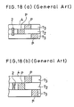
- the normal track mode as shown in FIG. 18(a) and, the wide track mode as shown in FIG. 18(b) are standardized.
- the normal track mode is applicable to recording and reproducing by a consumer.
- the wide track mode is applied to make prerecorded tapes which are recorded in factory.
- the output levels of the magnetic heads 2 and 3 reproducing the pilot signals P A , P B and P C are constant within a range of deflected angle (from +120° to -120°, for example).
- a magnetic tape reproducing apparatus having a characteristic of the level of the tracking error signal which is preferable to the normal track mode as shown by a dotted line L5 of FIG. 19 which is slightly different from an ideal characteristic represented by a solid ling L4, the characteristic of the level of the tracking error signal seriously changes as shown by a dotted line L7 of FIG. 20 which is different from the ideal characteristics of the level of the tracking error signal L6.
- An object of the present invention is to provide a tracking control circuit in which stable tracking servo operation is maintained.
- the tracking control circuit of the herical scanning magnetic tape apparatus in accordance with the present invention comprises: at least one magnetic head for reproducing recorded signals of a magnetic tape including pilot signals and a synchronizing signal, first filter means for passing the reproduced signal of the pilot signals, envelope detecting means for detecting envelope of the reproduced signal of the pilot signal, second filter means for passing the reproduced signal of the synchronizing signal, a synchronizing signal generator for creating timing signals on the basis of the reproduced signal of the synchronizing signal, calculating means for calculating a level of difference between the respective levels of the reproduced signals by affection of crosstalk of respective pilot signals recorded on both neighboring tracks of a track, a sample hold circuit for holding the level of difference between the respective levels of the two reproduced signals of the pilot signals in synchronism with the timing signal, a delay circuit for delaying the reproduced signal of the pilot signal of the track, an automatic gain control circuit for controlling the level of difference on the basis of the delayed reproduced signal of the pilot signal of the previous track.
- respective pilot signals of both neighboring tracks of the present reproducing track of a magnetic head are detected by affection of crosstalk, and a tracking error signal is created on the basis of a difference between the level of the detected respective pilot signals. Then the level of the tracking error signal is controlled by a signal including a pilot signal which is detected in reproducing step of other track.
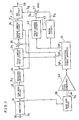
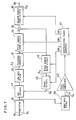
- FIG.1 is a circuit block diagram of a first embodiment of a tracking control circuit in accordance with the present invention.
- Two magnetic heads 2 and 3 in a magnetic tape transporting mechanism shown in FIG. 10 scan a magnetic tape 4.
- the magnetic head 2 or 3 moves in the direction of arrow E on the magnetic tape 4 which is transported in the direction of arrow D as shown in FIG.12.
- a reproduced signal S1 of the magnetic heads 2 and 3 are inputted into an amplifier 31 through an input terminal 30.
- the reproduced signal S1 composed of both the output signals of the magnetic heads 2 and 3 which are connected into one signal in a time sequence.
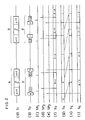
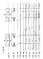
- FIG. 2(a) shows the reproduced signal S1.
- a signal A is reproduced by the magnetic head 2 and a signal B is reproduced by the magnetic head 3.
- the output of the amplifier 31 is applied to a low-pass filter 32 and a band-pass filter 39.
- the low-pass filter 32 allows to pass only early pilot signals P A , P B and P C and later pilot signals P D , P E and P F of the ATF signal as shown in FIG. 12, and digitalized signals of data and a synchronizing signal S of the ATF signal are eliminated.
- a reproduced pilot signal S2 in FIG.1 is composed of the reproduced signals of the pilot signals P A , P B and P C , and the waveform thereof is shown in FIG.13(a), 13(b) or 13(c).
- the reproduced pilot signal S2 applied to an envelope detector 33, and an envelope of the reproduced pilot signal S2 detected.
- FIG. 2(b) shows the reproduced pilot signal S2.
- letters a, f, i and j designate reproduced pilot signals of own track of each magnetic head 2 or 3.
- letters b, c, d, e, g, h, k and l designate pilot signals reproduced from the pilot signals of neighboring tracks which are detected by crosstalk.
- the reproduced pilot signals a, b, c, g, h and i are reproduced by the early pilot signals of tracks, and the reproduced pilot signals d, e, f, j, k and l are reproduced by the later pilot signals of the tracks.
- the output of the envelope detector 33 is applied to a first sample hold circuit 34, a third sample hold circuit 42 and an adder 35.
- the band-pass filter 39 allows to pass only the reproduced synchronizing signal S S of the synchronizing signal S.
- the synchronizing signal S S is applied to a zero-cross comparator 40, and a zero-cross time is detected.
- the output of the zero-cross comparator 40 is applied to a synchronizing signal generator 41, and synchronizing signals SP1, SP2 and SP3 which serve as timing signals are generated on the basis of the zero-cross time of the synchronizing signal S S .
- the synchronizing signal SP1 is generated during the period of reproduction of the pilot signal P B due to crosstalk as shown in FIG.2(c) and FIG.13(a), and is applied to the first sample-hold circuit 34.
- a level P1 of the reproduced signal of the pilot signal P B is held in the first sample-hold circuit 34.
- the output of the first sample-hold circuit 34 is applied to a positive input of an adder 35.
- the output of the envelope detector 33 is applied to a negative input of the adder 35.
- the adder 35 a difference between the value of the level P1 and the output value of the envelope detector 33 is detected and is held in synchronism with the synchronizing signal SP2 which is supplied from the synchronizing signal generator 41 with a second sample hold circuit 36.
- the synchronizing signal SP2 is generated during the period of reproduction of the pilot signal P C as shown in FIG. 2(d) and FIG.13(a). Consequently, the difference between the value of the level P1 and the value of the level P2 of the reproduced signal of the pilot signal P C is held in the second sample-hold circuit 36 of FIG. 1.
- the difference (P1-P2) is designated by “signal S3”, and is applied to an automatic gain control circuit 37 (hereinafter abbreviated as AGC circuit).
- AGC circuit automatic gain control circuit 37
- the level of the signal S3 is controlled at the AGC circuit 37 on the basis of a signal S6 which is elucidated hereinafter.
- FIG.2(f) is a time chart of the signal S3.
- a representation "b-c” represents the difference (P1-P2) between reproduced signals of the pilot signals P B and P C
- a representation "d-e” represents the difference (P1-P2) between reproduced signals of the pilot signals P D and P E , for example.
- the output of the envelope detector 33 is also applied to the third sample hold circuit 42 which is controlled by the synchronizing signal SP3.
- the synchronizing signal SP3 is generated during the period reproducing the pilot signal P A of own track of the magnetic head 2 as shown in FIG.2(e) and FIG.13(a). Consequently, the level of the output signal S4 of the third sample hold circuit 42 is equal to the level P3 of the reproduced signal of the pilot signal P A . Then the signal S4 is applied to a negative input of an adder 44.
- the time chart of the signal S4 is shown in FIG.2(g).
- the signal S4 is also applied to a delay circuit 43 which is controlled by the synchronizing signal SP3.
- the delay circuit 43 causes the signal 4 to delay by a time period between consecutive two reproduced pilot signals.
- a delayed signal S5, as shown in FIG.2(h) is output from the delay circuit 43.
- the delay time is equal to a time period between the pilot signals P A and P F .
- the delay time is equal to a time period between the pilot signals P F and P B .
- the signal S5 is applied to a positive input of the adder 44.
- the signal representing the difference between the two values is designated as "S6" in FIG.2(i).
- the signal S6 applied to the AGC circuit 37, and the level of the signal S3 is controlled by the signal S6 and is output from an output terminal 38.
- the output of the AGC circuit 37 is a tracking error signal which is applicable to the servo control system in a manner that will be familiar to one skilled in the art.
- the representation "f-i” represents a difference between a reproduced signal level of the signal "f” of own track of the magnetic head 2 and a reproduced signal level of the signal "i” of own track of the magnetic head 3 as shown in FIGs. 2(b) and 2(i).
- the reproduced signal levels of the signals g, h and f are lower than the reproduced signal levels of the signals d, e and i, respectively, and thus the difference "f-i" becomes a negative value.
- the AGC circuit 37 is made to increase its gain by applying a negative control signal.
- the gain of the AGC circuit 37 is increased by applying the negative signal of the difference "f-i"
- the output level of the AGC circuit 37 which is represented by the difference "g-h" (tracking error signal) increases.
- the improved characteristic of level of the tracking error signal in dotted line meets an ideal characteristic in solid line in the range of deflected angle from +120° to -120°
- stable servo control is realized without requiring any change of the gain of the tracking servo system.
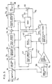
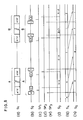
- FIG.5 is a circuit block diagram of a second embodiment of the present invention.
- the output of the envelope detector 33 is inputted into the adder 45 which is controlled by the synchronizing signals SP1 and SP2.
- the output of the adder 45 is applied to the positive input of the adder 46, and the output of the delay circuit 43 is applied to the other positive input thereof.
- the output of the adder 46 is applied to the AGC circuit 37.
- the adder 45 holds the output of the envelope detector 33 in synchronism with the synchronizing signals SP1 and SP2, and calculates a sum of levels P1 and P2. Then a signal S7 having the level of the sum is created as shown in FIG.6(g). The signal S7 is added to the signal S5 of the output of the delay circuit 43 with the adder 46, and a resultant signal S8 is created as shown in FIG.6(j). The signal S8 is applied to the AGC circuit 37 to be controlled the gain.
- the tracking error signal S3 is controlled by a sum of the level of the reproduced signal of the later pilot signal of a track detected during previous reproducing period, and the levels of the signals of the early pilot signals of both neighboring tracks of the next successive track which is presently in reproduction.
- the tracking error signal S3 represented by the difference "g-h” is controlled on the basis of the signal S8 represented by the sum "f + g + h".
- the AGC circuit 37 in this embodiment is made to vary its gain in inverse proportion to a level of a control signal applied thereto. Therefore the level of the tracking error signal S3 is inversely proportional to the level of the sum "f + g + h". For example, when the recorded level of the signal A is lower than that of the signal B, the level of the sum "f + g + h" is lowered. Consequently, the gain of the AGC circuit 37 increases, and the level of the tracking error signal S3 increases.
- FIG.7 is a circuit block diagram of a third embodiment of the present invention.
- an AGC circuit 47 is placed between the amplifier 31 and the low pass filter 32, and the output of the second sample hold circuit 36 is the tracking error signal.
- the output of the delay circuit 43 is applied to the AGC circuit 47, and remaining circuit is identical with that of the first embodiment.
- the signal S4 based on a later pilot signal is delayed by the delay circuit 43, and a control signal S5 is created.
- the control signal S5 is applied to the AGC circuit 47 during reproduction of the subsequent track. According to the third embodiment, therefore, the signal S5 controls the AGC circuit 47 in a direction to lessen a difference between the respective reproduced levels of neighboring two tracks.
- FIG.9 is a circuit block diagram of a fourth embodiment of the present invention.
- the AGC circuit 37 receives the output of the second sample-hold circuit 36, and is controlled by the output of the delay circuit 43.
- Difference of the fourth embodiment with respect to he first embodiment shown by FIG.1 is that the control signal S5 is directly inputted to the AGC circuit 37 from the delay circuit 43. Further technically, since a reproduced signal due to crosstalk of pilot signals of neighboring tracks is not included in the control signal S5 which is applied to the AGC circuit, even if the level of the tracking error signal S3 varies due to unstable contact between the head chip and the tape surface, serious variation of the level of the tracking error signal can be prevented.
- the third and fourth embodiment in a similar manner of the third embodiment, since the tracking error signal created depending on crosstalk of pilot signals of the neighboring tracks is controlled by a reproduced signal of the own track of the head, a serious variation of the tracking error signal is prevented. Moreover, the third and fourth embodiment is simplified in configuration in comparison with the first or second embodiment.
Landscapes
- Adjustment Of The Magnetic Head Position Track Following On Tapes (AREA)
Applications Claiming Priority (2)
| Application Number | Priority Date | Filing Date | Title |
|---|---|---|---|
| JP221911/88 | 1988-09-05 | ||
| JP63221911A JPH0740340B2 (ja) | 1988-09-05 | 1988-09-05 | ヘリカルスキャン方式テープ再生装置のトラッキング制御回路 |
Publications (3)
| Publication Number | Publication Date |
|---|---|
| EP0359019A2 true EP0359019A2 (de) | 1990-03-21 |
| EP0359019A3 EP0359019A3 (de) | 1991-09-04 |
| EP0359019B1 EP0359019B1 (de) | 1995-04-05 |
Family
ID=16774090
Family Applications (1)
| Application Number | Title | Priority Date | Filing Date |
|---|---|---|---|
| EP89115859A Expired - Lifetime EP0359019B1 (de) | 1988-09-05 | 1989-08-28 | Spurregelkreis für ein magnetisches Bandgerät mit Schraubenlinienabtastung |
Country Status (5)
| Country | Link |
|---|---|
| US (1) | US5003413A (de) |
| EP (1) | EP0359019B1 (de) |
| JP (1) | JPH0740340B2 (de) |
| KR (1) | KR920006621B1 (de) |
| DE (1) | DE68922051T2 (de) |
Cited By (3)
| Publication number | Priority date | Publication date | Assignee | Title |
|---|---|---|---|---|
| EP0630010A3 (de) * | 1993-05-28 | 1995-01-25 | Canon Kk | |
| WO1996034385A1 (de) * | 1995-04-28 | 1996-10-31 | Deutsche Thomson-Brandt Gmbh | Schrägspuraufnahme- und wiedergabegerät für daten |
| US5617268A (en) * | 1993-09-17 | 1997-04-01 | Matsushita Electric Industrial Co. Ltd. | Tracking control apparatus that switches polarity of tracking error signal according to detected kind of pilot signal |
Families Citing this family (9)
| Publication number | Priority date | Publication date | Assignee | Title |
|---|---|---|---|---|
| DE3840291A1 (de) * | 1988-11-30 | 1990-05-31 | Broadcast Television Syst | Verfahren und schaltungsanordnung zur wiedergabe von datensignalen |
| JPH02195560A (ja) * | 1989-01-24 | 1990-08-02 | Sony Corp | 再生方法 |
| US5251079A (en) * | 1989-12-30 | 1993-10-05 | Sony Corporation | Tracking control circuit including gain correction control |
| US5359475A (en) * | 1992-03-23 | 1994-10-25 | Minnesota Mining And Manufacturing Company | Air filter system for helical scanner drum with vented drum cover |
| JP3271210B2 (ja) * | 1993-05-11 | 2002-04-02 | ソニー株式会社 | 回転ヘッド型磁気記録再生装置 |
| US6005741A (en) * | 1993-05-28 | 1999-12-21 | Canon Kabushiki Kaisha | Reproducing apparatus using pilot signal crosstalk for tracking control and using pilot signals to eliminate a back lock condition |
| JPH06338106A (ja) * | 1993-05-28 | 1994-12-06 | Canon Inc | トラッキング制御装置 |
| JPH06349159A (ja) * | 1993-06-01 | 1994-12-22 | Canon Inc | トラッキング制御装置 |
| US5828514A (en) * | 1996-02-16 | 1998-10-27 | International Business Machines Corporation | Servo error detection in a noisy environment |
Family Cites Families (7)
| Publication number | Priority date | Publication date | Assignee | Title |
|---|---|---|---|---|
| CA1210147A (en) * | 1982-03-18 | 1986-08-19 | Hiroshi Yoshioka | Tracking controlling apparatus |
| JPS59161555U (ja) * | 1983-04-14 | 1984-10-29 | 日本ビクター株式会社 | トラツキングサ−ボ回路 |
| JPS60138753A (ja) * | 1983-12-26 | 1985-07-23 | Sony Corp | デイジタル信号の記録再生方法 |
| JPS60209952A (ja) * | 1984-03-31 | 1985-10-22 | Toshiba Corp | トラツキング装置 |
| JPS6166250A (ja) * | 1984-09-07 | 1986-04-05 | Sony Corp | トラツキング制御回路 |
| JPS62214543A (ja) * | 1986-03-14 | 1987-09-21 | Toshiba Corp | ヘリカルスキヤン方式テ−プ再生装置のトラツキング制御回路 |
| JPS6318565A (ja) * | 1986-07-11 | 1988-01-26 | Pioneer Electronic Corp | デジタル信号記録再生装置 |
-
1988
- 1988-09-05 JP JP63221911A patent/JPH0740340B2/ja not_active Expired - Lifetime
-
1989
- 1989-08-19 KR KR1019890011831A patent/KR920006621B1/ko not_active Expired
- 1989-08-28 DE DE68922051T patent/DE68922051T2/de not_active Expired - Fee Related
- 1989-08-28 EP EP89115859A patent/EP0359019B1/de not_active Expired - Lifetime
- 1989-08-31 US US07/401,229 patent/US5003413A/en not_active Expired - Fee Related
Cited By (6)
| Publication number | Priority date | Publication date | Assignee | Title |
|---|---|---|---|---|
| EP0630010A3 (de) * | 1993-05-28 | 1995-01-25 | Canon Kk | |
| US5875065A (en) * | 1993-05-28 | 1999-02-23 | Canon Kabushiki Kaisha | Information recording reproducing apparatus using pilot signals to correct tracking error |
| US5617268A (en) * | 1993-09-17 | 1997-04-01 | Matsushita Electric Industrial Co. Ltd. | Tracking control apparatus that switches polarity of tracking error signal according to detected kind of pilot signal |
| EP0644531A3 (de) * | 1993-09-17 | 1997-09-24 | Matsushita Electric Industrial Co Ltd | Informationswiedergabevorrichtung. |
| WO1996034385A1 (de) * | 1995-04-28 | 1996-10-31 | Deutsche Thomson-Brandt Gmbh | Schrägspuraufnahme- und wiedergabegerät für daten |
| US6094319A (en) * | 1995-04-28 | 2000-07-25 | Deutsche Thomson-Brandt Gmbh | Method and apparatus for tracking a helical track recording |
Also Published As
| Publication number | Publication date |
|---|---|
| EP0359019A3 (de) | 1991-09-04 |
| KR900005385A (ko) | 1990-04-14 |
| DE68922051T2 (de) | 1995-12-21 |
| KR920006621B1 (ko) | 1992-08-10 |
| JPH0740340B2 (ja) | 1995-05-01 |
| JPH0271419A (ja) | 1990-03-12 |
| DE68922051D1 (de) | 1995-05-11 |
| EP0359019B1 (de) | 1995-04-05 |
| US5003413A (en) | 1991-03-26 |
Similar Documents
| Publication | Publication Date | Title |
|---|---|---|
| US4714971A (en) | Method and apparatus for reproducing signals having improved rotary head tracking control | |
| EP0359019B1 (de) | Spurregelkreis für ein magnetisches Bandgerät mit Schraubenlinienabtastung | |
| CA1160741A (en) | Head tracking control system for a helical scan vtr | |
| US5182681A (en) | Rotating head magnetic recording and reproducing device having automatic tracking control function | |
| US4920435A (en) | Magnetic recording and reproducing device with improved track servo | |
| EP0227468B1 (de) | Aufnahme- und/oder Wiedergabegerät | |
| EP0436114B1 (de) | Spurregelkreis | |
| CA1118886A (en) | Automatic tracking for a videotape recorder | |
| US5055952A (en) | Automatic track finding (ATF) controller for digital audio tape recorder | |
| US5490017A (en) | Signal reproducing apparatus | |
| US5026509A (en) | Tracking control system for information reproducing apparatus | |
| US4860130A (en) | Rotary head type digital audio signal reproducing apparatus | |
| US5089918A (en) | Magnetic recording and/or reproducing apparatus having single head with two gaps and providing different lead angles in different operating states | |
| EP0316954B1 (de) | Wiedergabeverfahren für Bandrekorder mit Drehkopf | |
| US4965874A (en) | Magnetic recording and reproduction device with fast feed/rewind head to tape speed control | |
| US4743921A (en) | Information signal reproducing apparatus having a tracking control system | |
| JPS6249776B2 (de) | ||
| KR960012999B1 (ko) | 브이씨알의 헬리컬 헤드 트래킹 장치 | |
| US6195500B1 (en) | Phase control apparatus for video cassette recorder | |
| KR0170258B1 (ko) | 비데오 테이프 레코더의 캡스턴 모터 제어방법 | |
| KR910001211B1 (ko) | Dat의 제어신호기록방법 및 그 장치 | |
| KR0181071B1 (ko) | 비디오 카세트 레코더의 트랙킹 방법 | |
| JPS6040522A (ja) | オ−トトラツキング方式 | |
| JP3225629B2 (ja) | 再生装置 | |
| JPH0676254A (ja) | Dtヘッドのトラックずれ量検出装置 |
Legal Events
| Date | Code | Title | Description |
|---|---|---|---|
| PUAI | Public reference made under article 153(3) epc to a published international application that has entered the european phase |
Free format text: ORIGINAL CODE: 0009012 |
|
| 17P | Request for examination filed |
Effective date: 19890828 |
|
| AK | Designated contracting states |
Kind code of ref document: A2 Designated state(s): DE NL SE |
|
| PUAL | Search report despatched |
Free format text: ORIGINAL CODE: 0009013 |
|
| AK | Designated contracting states |
Kind code of ref document: A3 Designated state(s): DE NL SE |
|
| 17Q | First examination report despatched |
Effective date: 19930105 |
|
| GRAA | (expected) grant |
Free format text: ORIGINAL CODE: 0009210 |
|
| AK | Designated contracting states |
Kind code of ref document: B1 Designated state(s): DE NL SE |
|
| REF | Corresponds to: |
Ref document number: 68922051 Country of ref document: DE Date of ref document: 19950511 |
|
| PLBE | No opposition filed within time limit |
Free format text: ORIGINAL CODE: 0009261 |
|
| STAA | Information on the status of an ep patent application or granted ep patent |
Free format text: STATUS: NO OPPOSITION FILED WITHIN TIME LIMIT |
|
| 26N | No opposition filed | ||
| PGFP | Annual fee paid to national office [announced via postgrant information from national office to epo] |
Ref country code: SE Payment date: 19980806 Year of fee payment: 10 |
|
| PGFP | Annual fee paid to national office [announced via postgrant information from national office to epo] |
Ref country code: NL Payment date: 19980827 Year of fee payment: 10 |
|
| PGFP | Annual fee paid to national office [announced via postgrant information from national office to epo] |
Ref country code: DE Payment date: 19980907 Year of fee payment: 10 |
|
| PG25 | Lapsed in a contracting state [announced via postgrant information from national office to epo] |
Ref country code: SE Free format text: THE PATENT HAS BEEN ANNULLED BY A DECISION OF A NATIONAL AUTHORITY Effective date: 19990830 |
|
| PG25 | Lapsed in a contracting state [announced via postgrant information from national office to epo] |
Ref country code: NL Free format text: LAPSE BECAUSE OF NON-PAYMENT OF DUE FEES Effective date: 20000301 |
|
| EUG | Se: european patent has lapsed |
Ref document number: 89115859.4 |
|
| NLV4 | Nl: lapsed or anulled due to non-payment of the annual fee |
Effective date: 20000301 |
|
| PG25 | Lapsed in a contracting state [announced via postgrant information from national office to epo] |
Ref country code: DE Free format text: LAPSE BECAUSE OF NON-PAYMENT OF DUE FEES Effective date: 20000601 |