EP0358547A1 - Device for gripping and holding at least two flexible parts in order to assemble them by sewing or the like - Google Patents
Device for gripping and holding at least two flexible parts in order to assemble them by sewing or the like Download PDFInfo
- Publication number
- EP0358547A1 EP0358547A1 EP89402342A EP89402342A EP0358547A1 EP 0358547 A1 EP0358547 A1 EP 0358547A1 EP 89402342 A EP89402342 A EP 89402342A EP 89402342 A EP89402342 A EP 89402342A EP 0358547 A1 EP0358547 A1 EP 0358547A1
- Authority
- EP
- European Patent Office
- Prior art keywords
- support
- mold
- seat
- forming
- aforementioned
- Prior art date
- Legal status (The legal status is an assumption and is not a legal conclusion. Google has not performed a legal analysis and makes no representation as to the accuracy of the status listed.)
- Granted
Links
Images

Classifications
-
- D—TEXTILES; PAPER
- D05—SEWING; EMBROIDERING; TUFTING
- D05B—SEWING
- D05B11/00—Machines for sewing quilts or mattresses
- D05B11/005—Machines for sewing quilts or mattresses for sewing the edges of mattresses
-
- B—PERFORMING OPERATIONS; TRANSPORTING
- B68—SADDLERY; UPHOLSTERY
- B68G—METHODS, EQUIPMENT, OR MACHINES FOR USE IN UPHOLSTERING; UPHOLSTERY NOT OTHERWISE PROVIDED FOR
- B68G15/00—Auxiliary devices and tools specially for upholstery
- B68G15/005—Worktables or workframes
Definitions
- the present invention relates generally to a device for gripping and holding at least two pieces or sheets of flexible material with a view to their assembly by sewing, welding, or any suitable method.
- It relates more particularly to a device for gripping and holding two pieces of fabric or canvas intended to be assembled by sewing, one of these pieces having to constitute the covering surface of the upper part of a seat of an automobile seat and the another piece of fabric constituting a band surrounding this seat.
- the present invention aims to fill this gap by providing a gripping and holding device achieving the above objective, and this in a reliable and inexpensive manner.
- the invention relates to a device for gripping and holding at least two flexible parts in fabric for example, intended to be assembled by sewing or the like, and one of which forms a covering surface of the upper part of a seat cushion, for example, while the other forms a strip surrounding this seat, characterized in that that it comprises a support forming a mold capable of receiving said surface and said strip and comprising means allowing the peripheral clamping of these two elements by pressing a plate or the like on said support forming mold.
- the periphery of the mold-forming support is provided with a groove or the like capable of receiving the band surrounding the seat and defining, on the interior side of the support, a sole in the shape of the covering surface. from the upper part of the seat, and from the side outside the support, a flange constituting with the periphery of the plate, the aforementioned pinching means.
- the wall of the groove situated on the outside of the support and comprising the abovementioned flange is provided with orifices connected to a source of vacuum allowing the strip surrounding the seat to be pressed against said wall.
- the aforementioned plate can be actuated by a jack mounted articulated on a frame of which the support forming the mold is integral.
- This frame is fixed on a sleeve rotatably mounted on a part with end piece integral with the support forming the mold and capable of being grasped by the pliers of a robot.
- the plate applicable on the sole it is fixed to the frame by means of a bearing.
- connection of the plate to the frame by a bearing, and the connection of the support forming the mold to the frame by means of a sleeve integral with this frame will allow the plate and the support to rotate simultaneously relative to the frame so to automatically assemble the two pieces of fabric by sewing, as will be explained in detail below.
- the device according to this invention comprises indexing means for identifying the relative positions of the support forming the mold and the plate.
- This invention is further characterized by a cable associated with a return means and fixed to the frame to allow in particular the retention of the frame during the simultaneous rotation of the support forming the mold and the plate, this in order to allow assembly by sewing.
- the frame has substantially the shape of a U between the branches of which the mold-forming support and the plate are simultaneously rotatably mounted, the latter being secured, by means of the aforementioned bearing, to one branches of the U articulated on the remaining part of this U.
- the aforementioned sole receiving the piece of fabric intended to cover the upper part of the seat cushion is provided with means, such as for example asperities, preventing any sliding of this piece of fabric.
- a gripping and holding device in accordance with this invention essentially comprises a support forming a mold 1 which comprises on the one hand a sole 2 whose external face 2a can receive a piece of fabric, of canvas or the like 3 corresponding to the shape of the upper part of a seat of a vehicle seat for example, and on the other hand of the means 4 allowing the peripheral pinching of the part 3 and of another piece of fabric, canvas or the like 5 to be assembled to the part 3 and constituting a band to surround the seat of the seat (not shown).
- the support forming the mold 1 is provided with a groove or the like 6 capable of receive, in a substantially vertical orientation, the piece of fabric 5 and defining, on the interior side of the support 1, the sole 2 previously mentioned and which is, by its external face 2a, in the shape of the upper surface of the seat of the seat, and on the outside of the support 1, a flange 7 which can cooperate with the periphery 8 of a presser plate 9 so as to pinch the periphery of the pieces of fabric 3 and 5.
- this pinching is carried out a short distance from the peripheral edges of the pieces of fabric 3 and 5 so that these two edges are juxtaposed to form an edge or a fringe 10 which is free and external to the support forming the mold 1, which edge 10 can be sewn by the sewing head shown schematically at 11 in Figure 2 and this in the manner which will be explained later.
- the groove 6 which has substantially a cross section in the shape of a U or a V, comprises, on the inside of the support 1, a wall 6a which in a way constitutes the edge of the sole 2.
- the plate 9, like the mold forming the support 1, are integral with a frame generally identified at 15 and having the general shape of a U, as can be seen in FIGS. 1 and 2.
- One 16 of the branches of the U is articulated at 17 on the remaining part 18 of the U which is itself integral with a sleeve 19 mounted idly on a part 20 fixed on the support forming the mold 1 and carrying at its end an end piece removable 21 allowing the gripping of the entire device by the clamps 22 of a robot 23 visible in FIG. 2.
- the presser plate 9 On the end of the branch 16 of the frame 15 is fixed the presser plate 9 by means of a ball bearing 24, so that said plate can rotate relative to said branch or arm 16.
- a jack 25 is mounted in an articulated manner between the arm 16 and the remaining part 18 of the frame 15, so that, as will be described later in connection with operation, the pressure plate 9 can be moved away from or applied to the sole 2 of the mold support 1.
- Indexing means constituted, according to the example shown, by thrust bearings 27, 28 respectively allow the location of the relative positions of the pressure plate 9 and the support forming the mold 1.
- the outer face 2a of the sole 2 is provided with asperities preventing any sliding of the piece of fabric 3 relative to said sole.
- asperities one could perfectly, without departing from the scope of the invention, use other equivalent means.
- the plate 9-support 1 assembly can rotate simultaneously between the branches of the U constituting the frame 15, and this thanks to the ball bearing 24 and the sleeve bearing 19, it being understood that between this sleeve and the part 20 are provided with seals 31 ensuring airtightness in all the angular positions that the device takes during the operation which will now be described.
- the actuator 25 is actuated which lifts the arm 16 and consequently moves the pressure plate 9 away from the sole 2, so that access inside the mold support 1 is possible
- the operator firstly places the piece of fabric 5 constituting the surrounding of the seat base in the groove 6, taking care to place the outside or appearance of the fabric or the canvas on the side of the wall 6a of said groove, that is to say on the side of the sole 2. Then the operator creates a vacuum in the cavity or chamber 13 which, by means of the orifices 12, causes the part 5 to be held against the wall 6b.
- the piece of fabric 3 is deposited on the sole 2, so that the outer face or aspect of this piece is on the side of the face 2a of the sole 2. It will be specified here that any sliding of the piece of fabric 3 on the sole 2 is avoided by the roughness or other equivalent means, on the face 2a.
- the operator then controls the jack 25 to press the plate 9 on the sole 2 so that the pieces of fabric 3 and 5 are sandwiched by their peripheral edges, and this thanks to the cooperation of the edge 8 of the plate 9 and the rim 7, so as to leave a free edge 10 constituted by two superimposed fringes of part 3 and part 5.
- the robot 23 then grasps the device on the carousel by the end piece 21 and changes the device in front of the sewing head 11, as can be understood by referring to FIG. 2.
- the assembly 9-support plate 1 rotates relative to the frame 15 as the seam is made on the edge 10 formed by the two fringes of the pieces of fabric 3 and 5.
- the cable 29 performs an elastic traction on the frame 15 so as not to interfere with the automatic sewing operation.
- This finished part is then turned over, so as to reveal the outside or appearance of the fabric and to hide the seam, as can be seen in FIG. 4 where the seam is shown diagrammatically at 32.
- the assembly now holding the pieces of fabric to be joined can be fixed, while the sewing head is movable.
- the assembly for gripping and holding the pieces of fabric 3 and 5 can be considered as a fixed station template around which the sewing head moves, which can be animated by a robot.
- the maintenance of the piece of fabric 1 in position can be ensured in various ways, that is to say by using for example the electrostatic properties of this piece of fabric , or by still using a claw mechanism which would be movable inside the sole 2.
Landscapes
- Engineering & Computer Science (AREA)
- Mechanical Engineering (AREA)
- Textile Engineering (AREA)
- Sewing Machines And Sewing (AREA)
Abstract
Description
La présente invention se rapporte d'une manière générale à un dispositif de préhension et maintien d'au moins deux pièces ou feuilles de matériau souple en vue de leur assemblage par couture, soudage, ou tout procédé approprié.The present invention relates generally to a device for gripping and holding at least two pieces or sheets of flexible material with a view to their assembly by sewing, welding, or any suitable method.
Elle concerne plus particulièrement un dispositif de préhension et maintien de deux pièces de tissu ou de toile destinées à être assemblées par couture, l'une de ces pièces devant constituer la surface de recouvrement de la partie supérieure d'une assise de siège automobile et l'autre pièce de tissu constituant une bande entourant cette assise.It relates more particularly to a device for gripping and holding two pieces of fabric or canvas intended to be assembled by sewing, one of these pieces having to constitute the covering surface of the upper part of a seat of an automobile seat and the another piece of fabric constituting a band surrounding this seat.
On a déjà proposé divers systèmes pour réaliser d'une façon automatique ou semi-automatique la couture d'un certain nombre de pièces de tissu devant constituer un article.Various systems have already been proposed for automatically or semi-automatically sewing a certain number of pieces of fabric which must constitute an article.
Toutefois, il n'a pas encore été proposé un dispositif de préhension et maintien de deux pièces de tissu en vue de leur assemblage automatique par couture pour réaliser spécifiquement un revêtement d'assise de siège qui, comme on le sait constitue un élément présentant une forme relativement compliquée.However, a device has not yet been proposed for gripping and holding two pieces of fabric with a view to their automatic assembly by sewing in order to specifically produce a seat cushion covering which, as is known, constitutes an element having a relatively complicated shape.
Aussi, la présente invention a pour but de combler cette lacune en proposant un dispositif de préhension et de maintien réalisant l'objectif ci-dessus, et ce de manière fiable et peu coûteuse.Also, the present invention aims to fill this gap by providing a gripping and holding device achieving the above objective, and this in a reliable and inexpensive manner.
A cet effet, l'invention a pour objet un dispositif de préhension et maintien d'au moins deux pièces souples en tissu par exemple, destinées à être assemblées par couture ou analogue, et dont l'une forme surface de recouvrement de la partie supérieure d'une assise de siège par exemple, tandis que l'autre forme une bande entourant cette assise, caractérisé en ce qu'il comprend un support formant moule apte à recevoir ladite surface et ladite bande et comportant des moyens permettant le pinçage périphérique de ces deux éléments par appui d'un plateau ou analogue sur ledit support formant moule.To this end, the invention relates to a device for gripping and holding at least two flexible parts in fabric for example, intended to be assembled by sewing or the like, and one of which forms a covering surface of the upper part of a seat cushion, for example, while the other forms a strip surrounding this seat, characterized in that that it comprises a support forming a mold capable of receiving said surface and said strip and comprising means allowing the peripheral clamping of these two elements by pressing a plate or the like on said support forming mold.
Selon une autre caractéristique de cette invention, le pourtour du support formant moule est muni d'une rainure ou analogue apte à recevoir la bande entourant l'assise et définissant, du côté intérieur au support, une semelle à la forme de la surface de recouvrement de la partie supérieure de l'assise, et du côté extérieur au support, un rebord constituant avec la périphérie du plateau, les moyens de pinçage précités.According to another characteristic of this invention, the periphery of the mold-forming support is provided with a groove or the like capable of receiving the band surrounding the seat and defining, on the interior side of the support, a sole in the shape of the covering surface. from the upper part of the seat, and from the side outside the support, a flange constituting with the periphery of the plate, the aforementioned pinching means.
On précisera encore ici que la paroi de la rainure située du côté extérieur au support et comportant le rebord précité est munie d'orifices reliés à une source de vide permettant à la bande entourant l'assise de se plaquer contre ladite paroi.It will also be specified here that the wall of the groove situated on the outside of the support and comprising the abovementioned flange is provided with orifices connected to a source of vacuum allowing the strip surrounding the seat to be pressed against said wall.
Suivant une autre caractéristique de l'invention, le plateau précité est actionnable par un vérin monté articulé sur un bâti dont est solidaire le support formant moule.According to another characteristic of the invention, the aforementioned plate can be actuated by a jack mounted articulated on a frame of which the support forming the mold is integral.
Ce bâti est fixé sur un manchon monté rotatif sur une pièce avec embout solidaire du support formant moule et susceptible d'être saisi par les pinces d'un robot.This frame is fixed on a sleeve rotatably mounted on a part with end piece integral with the support forming the mold and capable of being grasped by the pliers of a robot.
Quant au plateau applicable sur la semelle, il est fixé au bâti par l'intermédiaire d'un roulement.As for the plate applicable on the sole, it is fixed to the frame by means of a bearing.
On comprend donc que la liaison du plateau au bâti par un roulement, et la liaison du support formant moule au bâti par l'intermédiaire d'un manchon solidaire de ce bâti permettront au plateau et au support de tourner simultanément par rapport au bâti de façon à réaliser automatiquement l'assemblage par couture des deux pièces de tissu, comme il sera expliqué en détail plus loin.It is therefore understood that the connection of the plate to the frame by a bearing, and the connection of the support forming the mold to the frame by means of a sleeve integral with this frame will allow the plate and the support to rotate simultaneously relative to the frame so to automatically assemble the two pieces of fabric by sewing, as will be explained in detail below.
Suivant encore une autre caractéristique, le dispositif selon cette invention comporte des moyens d'indexage pour repérer les positions relatives du support formant moule et du plateau.According to yet another characteristic, the device according to this invention comprises indexing means for identifying the relative positions of the support forming the mold and the plate.
Cette invention est encore caractérisée par un câble associé à un moyen de rappel et fixé au bâti pour permettre notamment la retenue du bâti lors de la rotation simultanée du support formant moule et du plateau, cela afin de permettre l'assemblage par couture.This invention is further characterized by a cable associated with a return means and fixed to the frame to allow in particular the retention of the frame during the simultaneous rotation of the support forming the mold and the plate, this in order to allow assembly by sewing.
Suivant un mode de réalisation préféré, le bâti présente sensiblement la forme d'un U entre les branches duquel est monté simultanément rotatif le support formant moule et le plateau, ce dernier étant solidaire, par l'intermédiaire du roulement précité, de l'une des branches du U articulée sur la partie restante de ce U.According to a preferred embodiment, the frame has substantially the shape of a U between the branches of which the mold-forming support and the plate are simultaneously rotatably mounted, the latter being secured, by means of the aforementioned bearing, to one branches of the U articulated on the remaining part of this U.
On précisera encore ici que la semelle précitée recevant la pièce de tissu destinée à recouvrir la partie supérieure de l'assise de siège, est munie de moyens, tels que par exemple des aspérités, empêchant tout glissement de cette pièce de tissu.It will also be specified here that the aforementioned sole receiving the piece of fabric intended to cover the upper part of the seat cushion, is provided with means, such as for example asperities, preventing any sliding of this piece of fabric.
Mais d'autres avantages et caractéristiques de l'invention apparaîtront mieux dans la description détaillée qui suit et se réfère aux dessins annexés, donnés uniquement à titre d'exemple, et dans lesquels :
- La figure 1 est une vue en élévation et coupe verticale d'un dispositif conforme aux principes de l'invention ;
- La figure 2 est une vue très schématique et en perspective de ce dispositif en position saisie par les pinces d'un robot pouvant manoeuvrer automatiquement le dispositif au voisinage d'une tête de couture ;
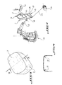
- La figure 3 est une vue schématique et en perspective de deux pièces de tissu assemblées et formant revêtement pour une assise de siège de véhicule ; et
- La figure 4 est une vue en coupe suivant la ligne IV-IV de la figure 3.
- Figure 1 is an elevational view in vertical section of a device according to the principles of the invention;
- Figure 2 is a very schematic perspective view of this device in the position gripped by the pliers of a robot that can automatically operate the device in the vicinity of a sewing head;
- Figure 3 is a schematic perspective view of two pieces of fabric assembled and forming a covering for a seat of a vehicle seat; and
- FIG. 4 is a sectional view along line IV-IV of FIG. 3.
Suivant l'exemple de réalisation représenté sur la figure 1, un dispositif de préhension et maintien conforme à cette invention comprend essentiellement un support formant moule 1 qui comporte d'une part une semelle 2 dont la face externe 2a peut recevoir une pièce de tissu, de toile ou analogue 3 correspondant à la forme de la partie supérieure d'une assise de siège de véhicule par exemple, et d'autre part des moyens 4 permettant le pinçage périphérique de la pièce 3 et d'une autre pièce de tissu, de toile ou analogue 5 devant être assemblée à la pièce 3 et constituant une bande devant entourer l'assise du siège (non représentée).According to the embodiment shown in FIG. 1, a gripping and holding device in accordance with this invention essentially comprises a support forming a mold 1 which comprises on the one hand a sole 2 whose external face 2a can receive a piece of fabric, of canvas or the like 3 corresponding to the shape of the upper part of a seat of a vehicle seat for example, and on the other hand of the means 4 allowing the peripheral pinching of the
En se reportant à la figure 3, on voit clairement les pièces de tissu 3 et 5 lorsqu'elles ont été assemblées par couture, comme on le décrira plus loin, et qui forment en quelque sorte une housse recouvrant l'assise du siège.Referring to Figure 3, we clearly see the pieces of
Revenant à la figure 1, on voit que le support formant moule 1 est muni d'une rainure ou analogue 6 apte à recevoir, suivant une orientation sensiblement verticale, la pièce de tissu 5 et définissant, du côté intérieur au support 1, la semelle 2 précédemment citée et qui est, par sa face externe 2a, à la forme de la surface supérieure de l'assise du siège, et du côté extérieur au support 1, un rebord 7 qui peut coopérer avec la périphérie 8 d'un plateau-presseur 9 de façon à réaliser le pinçage de la périphérie des pièces de tissu 3 et 5. Plus précisément, comme on le voit bien sur la figure 1, ce pinçage est réalisé à une courte distance des bords périphériques des pièces de tissu 3 et 5 de façon que ces deux bords soient juxtaposés pour former un bord ou une frange 10 qui est libre et extérieure au support formant moule 1, lequel bord 10 pourra être cousu par la tête de couture représentée schématiquement en 11 sur la figure 2 et cela de la manière qui sera expliqué ultérieurement.Returning to FIG. 1, it can be seen that the support forming the mold 1 is provided with a groove or the like 6 capable of receive, in a substantially vertical orientation, the piece of fabric 5 and defining, on the interior side of the support 1, the sole 2 previously mentioned and which is, by its external face 2a, in the shape of the upper surface of the seat of the seat, and on the outside of the support 1, a flange 7 which can cooperate with the periphery 8 of a
La rainure 6 qui présente sensiblement en section transversale la forme d'un U ou d'un V, comporte, du côté intérieur au support 1 une paroi 6a qui constitue en quelque sorte le bord de la semelle 2. L'autre paroi 6b de la rainure 6, située du côté extérieur au support 1, et formant, à son extrémité supérieure, le rebord 7, est munie d'un grand nombre de petits orifices 12 reliés à une source de vide (non représentée) et permettant à la pièce ou bande de tissu 5 d'être plaquée par le vide contre la paroi 6b de la rainure 6. Plus précisément, les orifices 12 communiquent avec une chambre 13 reliée à la source de vide par une canalisation montrée schématiquement en 14.The
Le plateau 9, de même que le moule formant support 1, sont solidaires d'un bâti repéré d'une manière générale en 15 et présentant la forme générale d'un U, comme on le voit bien sur les figures 1 et 2.The
L'une 16 des branches du U est articulée en 17 sur la partie restante 18 du U qui est elle-même solidaire d'un manchon 19 monté fou sur une pièce 20 fixée sur le support formant moule 1 et portant à son extrémité un embout démontable 21 permettant la préhension de l'ensemble du dispositif par les pinces 22 d'un robot 23 visible sur la figure 2.One 16 of the branches of the U is articulated at 17 on the
Sur l'extrémité de la branche 16 du bâti 15 est fixé le plateau-presseur 9 par l'intermédiaire d'un roulement à billes 24, de sorte que ledit plateau peut tourner par rapport à ladite branche ou bras 16.On the end of the
Un vérin 25 est monté de manière articulée entre le bras 16 et la partie restante 18 du bâti 15, de sorte que, comme on le décrira plus loin à propos du fonctionnement, le plateau-presseur 9 peut être éloigné de ou appliqué sur la semelle 2 du support formant moule 1.A
On a montré schématiquement en 26 les conduits d'amenée et de retour de fluide hydraulique au vérin 25 qui est un vérin à double effet.There is shown schematically at 26 the hydraulic fluid supply and return conduits to the
Des moyens d'indexage constitués, suivant l'exemple représenté, par des butées à billes 27, 28 permettent respectivement le repérage des positions relatives du plateau-presseur 9 et du support formant moule 1.Indexing means constituted, according to the example shown, by
Au bâti 15, et plus précisément à la partie 18 de ce bâti, est fixée, comme on le voit bien sur les figures 1 et 2, l'extrémité d'un câble 29 associé à un moyen de rappel (non représenté) et enroulé sur un système d'enroulement montré schématiquement en 30 sur la figure 2. Ce câble permet notamment la retenue du bâti 15 lors de la rotation de l'ensemble plateau 9-support 1 provoquée par le robot 23, et cela de façon à réaliser la couture par la tête de couture 11, comme on l'expliquera plus loin à propos du fonctionnement.To the
La face extérieure 2a de la semelle 2 est munie d'aspérités évitant tout glissement de la pièce de tissu 3 par rapport à ladite semelle. Au lieu d'aspérités, on pourrait parfaitement, sans sortir du cadre de l'invention, utiliser d'autres moyens équivalents.The outer face 2a of the sole 2 is provided with asperities preventing any sliding of the piece of
On comprend donc de tout ce qui précède que l'ensemble plateau 9-support 1 peut tourner simultanément entre les branches du U constituant le bâti 15, et cela grace au roulement à billes 24 et au palier à manchon 19, étant entendu qu'entre ce manchon et la pièce 20 sont prévus des joints 31 assurant l'étanchéité à l'air dans toutes les positions angulaires que prend le dispositif pendant le fonctionnement qui sera décrit maintenant.It is therefore understood from all of the above that the plate 9-support 1 assembly can rotate simultaneously between the branches of the U constituting the
Tout d'abord, le chargement est effectué de la façon suivante.First of all, the loading is carried out as follows.
Le plateau 9 et le support 1 étant relativement positionnés grâce aux butées à billes 27 et 28 respectivement, on actionne le vérin 25 qui soulève le bras 16 et éloigne par conséquent le plateau-presseur 9 de la semelle 2, de sorte que l'accès à l'intérieur du support formant moule 1 est possibleThe
L'opérateur place tout d'abord la pièce de tissu 5 constituant l'entourage de l'assise du siège dans la rainure 6 en ayant soin de placer la face extérieure ou d'aspect du tissu ou de la toile du côté de la paroi 6a de ladite rainure, c'est-à-dire du côté de la semelle 2. Ensuite l'opérateur créé un vide dans la cavité ou chambre 13 qui, par l'intermédiaire des orifices 12, provoque le maintien de la pièce 5 contre la paroi 6b.The operator firstly places the piece of fabric 5 constituting the surrounding of the seat base in the
Puis, la pièce de tissu 3 est déposée sur la semelle 2, de manière que la face extérieure ou d'aspect de cette pièce soit du côté de la face 2a de la semelle 2. On précisera ici que tout glissement de la pièce de tissu 3 sur la semelle 2 est évité grâce aux aspérités ou autres moyens équivalents, sur la face 2a.Then, the piece of
L'opérateur commande ensuite le vérin 25 pour presser le plateau 9 sur la semelle 2 de sorte que les pièces de tissu 3 et 5 sont prises en sandwich par leurs bords périphériques, et cela grâce à la coopération du bord 8 du plateau 9 et du rebord 7, de façon à laisser un bord libre 10 constitué par deux franges superposées de la pièce 3 et de la pièce 5.The operator then controls the
Toutes les opérations ci-dessus sont effectuées, alors que le dispositif représenté sur la figure 1 est situé sur un carrousel (non représenté) qui peut acheminer successivement plusieurs tels dispositifs au voisinage du poste constitué par le robot 23. On observera ici que l'embout 21 est avantageusement utilisé pour maintenir le dispositif sur le carrousel.All the above operations are carried out, while the device shown in FIG. 1 is located on a carousel (not shown) which can successively route several such devices in the vicinity of the station constituted by the
Le robot 23 vient alors saisir le dispositif sur le carrousel par l'embout 21 et fait évoluer le dispositif devant la tête de couture 11, comme on peut le comprendre en se reportant à la figure 2. En d'autres termes, l'ensemble plateau 9-support 1 tourne par rapport au bâti 15 au fur et à mesure que la couture est effectuée sur le bord 10 constitué par les deux franges des pièces de tissu 3 et 5. Lors de cette opération, le câble 29 effectue une traction élastique sur le bâti 15 de façon à ne pas gêner l'opération automatique de couture.The
La couture étant terminée, l'opérateur relâche l'action du vérin 25, de sorte que le plateau 9 est soulevé, comme montré en traits fantômes sur la figure 1. La pression atmosphérique est rétablie dans la chambre ou cavité 13, ce qui provoque le relâchement de la pièce de tissu 5 destinée à former l'entourage de l'assise.The sewing being finished, the operator releases the action of the
L'accès au dispositif montré sur la figure 1 est alors possible et la pièce cousue est retirée.Access to the device shown in Figure 1 is then possible and the sewn part is removed.
Cette pièce finie est alors retournée, de manière à faire apparaître la face extérieure ou d'aspect du tissu et à cacher la couture, comme on le voit bien sur la figure 4 où la couture est montrée schématiquement en 32.This finished part is then turned over, so as to reveal the outside or appearance of the fabric and to hide the seam, as can be seen in FIG. 4 where the seam is shown diagrammatically at 32.
Bien entendu, l'invention n'est nullement limitée au mode de réalisation décrit et illustré qui n'a été donné qu'à titre d'exemple.Of course, the invention is in no way limited to the embodiment described and illustrated, which has been given only by way of example.
C'est ainsi que l'ensemble maintenant les pièces de tissu à réunir peut être fixe, alors que la tête de couture est mobile. Autrement dit, l'ensemble de préhension et maintien des pièces de tissu 3 et 5 peut être considéré comme un gabarit à poste fixe autour duquel évolue la tête de couture qui peut être animée par un robot. Egalement pour éviter l'encombrement du bras 5 et du plateau 9, le maintien de la pièce de tissu 1 en position peut être assuré de diverses manières, c'est-à-dire en utilisant par exemple les propriétés électrostatiques de cette pièce de tissu, ou en utilisant encore un mécanisme à griffes qui serait mobile à l'intérieur de la semelle 2.This is how the assembly now holding the pieces of fabric to be joined can be fixed, while the sewing head is movable. In other words, the assembly for gripping and holding the pieces of
C'est dire que l'invention comprend tous les équivalents techniques des moyens décrits ainsi que leurs combinaisons si celles-ci sont effectuées suivant son esprit.This means that the invention includes all the technical equivalents of the means described, as well as their combinations if these are carried out according to the spirit.
Claims (10)
Applications Claiming Priority (2)
| Application Number | Priority Date | Filing Date | Title |
|---|---|---|---|
| FR8811755 | 1988-09-08 | ||
| FR8811755A FR2636058B1 (en) | 1988-09-08 | 1988-09-08 | DEVICE FOR GRIPPING AND HOLDING AT LEAST TWO FLEXIBLE PIECES FOR THEIR SEWING OR THE LIKE |
Publications (2)
| Publication Number | Publication Date |
|---|---|
| EP0358547A1 true EP0358547A1 (en) | 1990-03-14 |
| EP0358547B1 EP0358547B1 (en) | 1993-07-28 |
Family
ID=9369831
Family Applications (1)
| Application Number | Title | Priority Date | Filing Date |
|---|---|---|---|
| EP19890402342 Expired - Lifetime EP0358547B1 (en) | 1988-09-08 | 1989-08-24 | Device for gripping and holding at least two flexible parts in order to assemble them by sewing or the like |
Country Status (3)
| Country | Link |
|---|---|
| EP (1) | EP0358547B1 (en) |
| DE (1) | DE68907826T2 (en) |
| FR (1) | FR2636058B1 (en) |
Cited By (2)
| Publication number | Priority date | Publication date | Assignee | Title |
|---|---|---|---|---|
| WO1997006300A1 (en) * | 1995-08-08 | 1997-02-20 | Moll Automatische Nähsysteme Gmbh | Method and device for forming a three-dimensional jacket |
| CN105129482A (en) * | 2015-07-16 | 2015-12-09 | 合肥奥瑞数控科技有限公司 | Fixing devices for control type cloth pressing device |
Families Citing this family (3)
| Publication number | Priority date | Publication date | Assignee | Title |
|---|---|---|---|---|
| DE102015200720B4 (en) | 2014-07-02 | 2021-05-20 | Adient Luxembourg Holding S.À R.L. | Feeding device and manufacturing device for sewing blanks of the same contour |
| CN104724659A (en) * | 2015-03-20 | 2015-06-24 | 苏州琼派瑞特电子科技有限公司 | Machine for loading pillow inner |
| DE102015109103B3 (en) * | 2015-06-09 | 2016-09-29 | Benteler Automobiltechnik Gmbh | Arrangement and method for sewing a fiber material blank |
Citations (2)
| Publication number | Priority date | Publication date | Assignee | Title |
|---|---|---|---|---|
| US1460399A (en) * | 1922-05-04 | 1923-07-03 | Derby & Co Inc P | Art of upholstery |
| FR994020A (en) * | 1944-12-06 | 1951-11-09 | Assembly device for sewing pieces of leather goods assembled at an angle |
-
1988
- 1988-09-08 FR FR8811755A patent/FR2636058B1/en not_active Expired - Fee Related
-
1989
- 1989-08-24 EP EP19890402342 patent/EP0358547B1/en not_active Expired - Lifetime
- 1989-08-24 DE DE1989607826 patent/DE68907826T2/en not_active Expired - Lifetime
Patent Citations (2)
| Publication number | Priority date | Publication date | Assignee | Title |
|---|---|---|---|---|
| US1460399A (en) * | 1922-05-04 | 1923-07-03 | Derby & Co Inc P | Art of upholstery |
| FR994020A (en) * | 1944-12-06 | 1951-11-09 | Assembly device for sewing pieces of leather goods assembled at an angle |
Cited By (2)
| Publication number | Priority date | Publication date | Assignee | Title |
|---|---|---|---|---|
| WO1997006300A1 (en) * | 1995-08-08 | 1997-02-20 | Moll Automatische Nähsysteme Gmbh | Method and device for forming a three-dimensional jacket |
| CN105129482A (en) * | 2015-07-16 | 2015-12-09 | 合肥奥瑞数控科技有限公司 | Fixing devices for control type cloth pressing device |
Also Published As
| Publication number | Publication date |
|---|---|
| DE68907826D1 (en) | 1993-09-02 |
| FR2636058A1 (en) | 1990-03-09 |
| EP0358547B1 (en) | 1993-07-28 |
| DE68907826T2 (en) | 1994-02-10 |
| FR2636058B1 (en) | 1990-11-30 |
Similar Documents
| Publication | Publication Date | Title |
|---|---|---|
| FR2475105A1 (en) | MECHANISM FORMING HINGE FOR AUTOMOTIVE VEHICLE TRUNK COVER | |
| FR2729885A1 (en) | Cutting device for layers of material, with groove to mark required cutting line | |
| EP0358547B1 (en) | Device for gripping and holding at least two flexible parts in order to assemble them by sewing or the like | |
| FR2607093A1 (en) | Vehicle capable of moving over a surface of any orientation | |
| FR2657553A1 (en) | METHOD AND APPARATUS FOR AUTOMATIC MOUNTING AND TIGHTENING OF COLLARS. | |
| EP0463952A1 (en) | Method for sharpening the blades of a rotary drum and adjusting the fixed counter-cutter cooperating with them, and device for carrying out this method | |
| FR2764254A1 (en) | MOBILE STEP DEVICE FOR A MOTOR VEHICLE | |
| EP0141745A1 (en) | Automatic machine for bending thin and rectilinear elements, especially metal wire, into a spatial configuration | |
| FR2590955A1 (en) | APPARATUS FOR ATTACHING JUNCTION CLIPS TO A CARRIER OR SIMILAR CARPET | |
| EP0267109A1 (en) | Automatic welding robot electrode replacing device | |
| EP0296442B1 (en) | Valve for vacuum container | |
| EP1617740B1 (en) | Multi-part last for manufacturing shoes | |
| FR2952023A1 (en) | DEVICE FOR ASSISTING THE INSTALLATION OF A WINDSCREEN OR THE LIKE | |
| EP0726123B1 (en) | Robot-held tool for automatically fitting sealing strips | |
| EP0734338A1 (en) | Mounting of one wheel of a motorcycle on a stand and test stand therefor provided with roller | |
| EP1319479B1 (en) | Device for transferring industrial objects between two positions | |
| FR2660219A1 (en) | Rivet-snapping machine | |
| LU86110A1 (en) | ACTUATOR FOR THE MOVEMENT OF A TOOL AND CARCASS TRANSFER DEVICE FOR PNEUMATIC TIRES USING THE SAME | |
| FR2764253A1 (en) | MOBILE STEP DEVICE FOR A MOTOR VEHICLE | |
| FR2483269A1 (en) | Reel unwinding starter and guide - has starting head passing under reel end actuated by hydraulic jack mounted on frame | |
| FR2606965A1 (en) | Film retention device for an unrolling and seeding machine | |
| FR3103127A1 (en) | Grip assistance system | |
| FR2646370A1 (en) | Installation for laying down a seal into the groove of an opening such as a vehicle door | |
| FR2705605A1 (en) | Device for removing a motor vehicle door by lifting it up axially using a robot | |
| FR2490128A1 (en) | Resistance spot welding gun - has gun arm holder movable along cam groove to cooperate with stationary arm |
Legal Events
| Date | Code | Title | Description |
|---|---|---|---|
| PUAI | Public reference made under article 153(3) epc to a published international application that has entered the european phase |
Free format text: ORIGINAL CODE: 0009012 |
|
| AK | Designated contracting states |
Kind code of ref document: A1 Designated state(s): DE GB IT |
|
| 17P | Request for examination filed |
Effective date: 19900421 |
|
| 17Q | First examination report despatched |
Effective date: 19921229 |
|
| GRAA | (expected) grant |
Free format text: ORIGINAL CODE: 0009210 |
|
| AK | Designated contracting states |
Kind code of ref document: B1 Designated state(s): DE GB IT |
|
| PGFP | Annual fee paid to national office [announced via postgrant information from national office to epo] |
Ref country code: GB Payment date: 19930816 Year of fee payment: 5 |
|
| PGFP | Annual fee paid to national office [announced via postgrant information from national office to epo] |
Ref country code: DE Payment date: 19930823 Year of fee payment: 5 |
|
| REF | Corresponds to: |
Ref document number: 68907826 Country of ref document: DE Date of ref document: 19930902 |
|
| ITF | It: translation for a ep patent filed |
Owner name: DE DOMINICIS & MAYER S. |
|
| GBT | Gb: translation of ep patent filed (gb section 77(6)(a)/1977) |
Effective date: 19931013 |
|
| PLBE | No opposition filed within time limit |
Free format text: ORIGINAL CODE: 0009261 |
|
| STAA | Information on the status of an ep patent application or granted ep patent |
Free format text: STATUS: NO OPPOSITION FILED WITHIN TIME LIMIT |
|
| 26N | No opposition filed | ||
| PG25 | Lapsed in a contracting state [announced via postgrant information from national office to epo] |
Ref country code: GB Effective date: 19940824 |
|
| GBPC | Gb: european patent ceased through non-payment of renewal fee |
Effective date: 19940824 |
|
| PG25 | Lapsed in a contracting state [announced via postgrant information from national office to epo] |
Ref country code: DE Effective date: 19950503 |
|
| PG25 | Lapsed in a contracting state [announced via postgrant information from national office to epo] |
Ref country code: IT Free format text: LAPSE BECAUSE OF NON-PAYMENT OF DUE FEES;WARNING: LAPSES OF ITALIAN PATENTS WITH EFFECTIVE DATE BEFORE 2007 MAY HAVE OCCURRED AT ANY TIME BEFORE 2007. THE CORRECT EFFECTIVE DATE MAY BE DIFFERENT FROM THE ONE RECORDED. Effective date: 20050824 |