EP0356157A2 - Connecteur électrique ayant un loquet antisurcharge - Google Patents
Connecteur électrique ayant un loquet antisurcharge Download PDFInfo
- Publication number
- EP0356157A2 EP0356157A2 EP89308379A EP89308379A EP0356157A2 EP 0356157 A2 EP0356157 A2 EP 0356157A2 EP 89308379 A EP89308379 A EP 89308379A EP 89308379 A EP89308379 A EP 89308379A EP 0356157 A2 EP0356157 A2 EP 0356157A2
- Authority
- EP
- European Patent Office
- Prior art keywords
- latch
- housing
- electrical connector
- latch structure
- connector housing
- Prior art date
- Legal status (The legal status is an assumption and is not a legal conclusion. Google has not performed a legal analysis and makes no representation as to the accuracy of the status listed.)
- Granted
Links
Images


Classifications
-
- H—ELECTRICITY
- H01—ELECTRIC ELEMENTS
- H01R—ELECTRICALLY-CONDUCTIVE CONNECTIONS; STRUCTURAL ASSOCIATIONS OF A PLURALITY OF MUTUALLY-INSULATED ELECTRICAL CONNECTING ELEMENTS; COUPLING DEVICES; CURRENT COLLECTORS
- H01R13/00—Details of coupling devices of the kinds covered by groups H01R12/70 or H01R24/00 - H01R33/00
- H01R13/62—Means for facilitating engagement or disengagement of coupling parts or for holding them in engagement
- H01R13/627—Snap or like fastening
- H01R13/6271—Latching means integral with the housing
- H01R13/6272—Latching means integral with the housing comprising a single latching arm
Definitions
- latch means for securely but releasably retaining a pair of electrical connector housings in a mated condition. More particularly, these prior art connectors include mateable pairs of molded plastics housings, each of which is constructed to receive a plurality of terminals therein. The terminals of one housing electrically contact the terminals of the other housing when the housings are in their mated condition.
- Unitarily molded electrical connector housings are generally considered desirable in that they yield certain manufacturing efficiencies, simplify the installation and use of the connector and minimize inventory management problems. Thus, it is often desirable to unitarily mold an entire electrical connector housing, including the latch means thereof.
- electrical connectors are used in environments where they will be repeatedly connected and disconnected by personnel having relatively little familiarity with the mechanics and intended use of the connector.
- electrical connectors often are employed in photostatic copiers and other office equipment that may periodically be serviced by field technicians or by the office staff that uses the copier or other such business machine.
- Field technicians often are not adequately trained on the proper usage of every electrical connector they are likely to encounter.
- Office personnel using various business machines typically have even less training and familiarity with the electrical connectors they may periodically be required to connect and/or disconnect.
- U.S. Patent No. 4,462,654 which issued to Aiello on July 31, 1984 shows a latch integrally and pivotally connected to a housing.
- the forward end of the latch extends from the pivoted connection to define a latch portion which is engageable with corresponding structure on a mateable housing.
- the rearward end of the latch member extends in the opposite direction from the pivot and includes an overstress stop which is pivotable into a lug or wall on the electrical connector housing.
- Contact between the overstress stop and the lug or wall of the electrical connector housing is intended to limit the amount of rotation around the pivot point during the normal engagement of the electrical connector housings.
- latch members on many elec trical connectors are cantilevered structures that effectively function as fishhooks which may catch insulated leads as the electrical connector is being inserted into or removed from an electrical apparatus.
- Fishhooking can damage an adjacent circuit that is unintentionally caught by the latch structure of the electrical connector housing.
- an attempt to operate the latch structure while a wire or other lead is in its fishhooked engagement can permanently damage the latch.
- U.S. Patent No. 4,272,145 which issued to LaDuke on June 9, 1981 includes a guard plate disposed in proximity to a lever arm to prevent unintentional fishhooking of wires that may be disposed in proximity to the electrical connector housing.
- the electrical connector housing shown in U.S. Patent No. 4,272,145 provides no anti-overstress protection, and the anti-overstress protection shown in the above-described U.S. Patent No. 4,462,654 could not readily be incorporated into the design of U.S. Patent No. 4,272,145.
- an object of the subject invention to provide an electrical connector housing constructed to positively prevent overstress of a latch structure thereof.
- the subject invention is directed to an electrical connector having a nonconductive housing.
- the housing may be unitarily molded from a plastic material and comprises a plurality of recesses or cavities for receiving electrical terminals therein.
- the nonconductive housing of the electrical connector comprises a latch structure deflectably extending therefrom.
- the latch structure may comprise a ramped locking means disposed to engage corresponding structure on a mateable electrical connector housing.
- sliding contact between the ramped locking means and the opposed mateable electrical connector housing will cause the latch structure to deflect.
- the deflectable latch structure will resiliently return to its initial undeflected condition, such that the locking means thereof may engage corresponding structure on the opposed mateable electrical connector housing.
- the latch structure may comprise release actuator means for manually and/or mechanically deflecting the latch structure to facilitate release of the locking means from the opposed mateable electrical connector housing, and thereby enabling disconnection of the two electrical connectors.
- the electrical connector housing of the subject invention comprises at least one rib disposed in proximity to the deflectable latch structure. More particularly, the anti-fishhook rib extends from the electrical connector housing at a location thereon generally adjacent an end of the latch structure which could otherwise fishhook an adjacent lead.
- the rib for preventing the latch structure from fishhooking adjacent insulated conductive leads may be unitarily molded with the electrical conductor housing.
- the housing may comprise a pair of ribs disposed on opposite sides of the latch structure for positively preventing fishhooking of insulated conductive leads by the latch structure.
- the electrical connector housing of the subject invention further comprises means for preventing overstressing of the latch structure.
- the anti-overstressing means preferably is disposed at the end of the latch structure which would undergo the greatest deflection during the mating and unmating of the electrical connector.
- the anti-overstress means may be disposed in spaced relationship to a surface of the electrical connector housing toward which the latch structure is deflectable for positively limiting the amount of deflection of the latch structure away from adjacent surfaces of the electrical connector housing.
- the anti-overstress means may be unitarily molded with the electrical connector housing. Additionally, the anti-overstress means may extend unitarily from the rib for preventing fishhooking.
- the anti-overstress means may extend unitarily from an anti-fishhook rib in generally spaced relationship to a cantilevered latch structure, such that the free end of the cantilevered latch structure is disposed intermediate the anti-overstress means and the adjacent surface of the electrical connector housing.
- the latch structure is deflectable between adjacent parts of the electrical connector housing and the anti-overstress means. The anti-overstress means, therefore, positively prevents over-deflection of the latch structure away from the electrical connector housing.
- a pair of anti-fishhooking ribs are provided, with each anti-fishhooking rib comprising an anti-overstress arm extending unitarily therefrom for limiting the amount of deflection of the latch structure relative to other portions of the electrical connector.
- the anti-overstress means may extend unitarily between a pair of spaced apart anti-fishhooking ribs to effectively define a bridge which limits the deflection of the latch structure.
- the anti-overstress means will be disposed generally at a location of maximum deflection of the cantilevered latch structure.
- the anti-overstress means may be integral with the latch structure.
- the latch structure is not cantilevered, but rather is supported at opposed ends, and is resiliently deflectable intermediate the opposed ends.
- the locking protrusion or other such releaseable locking means may be disposed at a location along the latch structure intermediate the opposed supports thereof.
- the supports of the latch structure at one or both ends simultaneously perform both an anti-overstress function and an anti-fishhooking function.
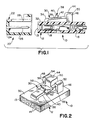
- the electrical connector 10 (see Fig. 1) comprises a unitarily molded plastics housing 12 having a forward mating end 13 and a plurality of cavities 14 with conductive terminals 16 securely mounted therein.
- the terminals 16 each comprise a conductor engaging end (not shown) for making electrical contact with a conductive lead, such as an individually insulated wire, a ribbon cable or the like.
- the conductor engaging end of the terminal 16 may comprise insulation displacement means or crimp means for engaging the conductive lead.
- the terminal 14 further comprises a mating end 18, which, as depicted in FIG. 1, defines a female pin receiving contact structure.
- the terminal 16 typically will be part of a DC signal line, with the connector 10 being used, for example, in a photostatic copier or other such business machine.
- the electrical connector 10 defines a male connector which is mateable with a female connector indicated generally by the numeral 20 in FIG. 1.
- the female connector 20 comprises a nonconductive housing 22 and a plurality of pin terminals 24 securely mounted therein.
- Each pin terminal 24 comprises a conductor engaging end (not shown) and an opposed mating end 26.
- the mating end 26 of the pin terminals 24 are engageable in the pin receiving contact structure at the mating end 18 of terminals 16 in the electrical connector 10.
- the nonconductive housing 22 of the female electrical connector 20 is formed with a locking aperture 28 extending entirely therethrough.
- the locking aperture 28 of the electrical connector 20 is engageable with a deflectable latch structure 30 on the electrical connector 10 as shown in both FIGS. 1 and 2.
- the latch structure 30 is molded unitarily with the nonconductive housing 12 and extends unitarily from the generally planar surface 32 of the nonconductive housing 12.
- the latch structure 30 comprises a base 34 which extends unitarily from the surface 32 of the nonconductive housing 12.
- a deflectable arm 36 extends from the base 34 in spaced relationship to the surface 32 of the nonconductive housing 12 and generally away from the mating end 13 of the housing 12.
- a locking protrusion 38 extends from the deflectable arm portion 36 of the latch structure 30 from the side thereof opposite surface 32 of the housing 12.
- the locking protrusion 38 comprises a ramped forward surface 40 and a rearward locking surface 42 which is aligned generally orthogonal to the surface 32 of the housing 12.
- the rearward locking surface 42 is disposed along the connector 10 at a location to engage the locking aperture 28 in the housing 22 of electrical connector 20 show in FIG. 1. More particularly, the mateable housings 12 and 22 are dimensioned such that the ramped forward surface 40 of the locking protrusion 38 on the housing 12 will cammingly engage the housing 22 during the forwardly directed mateable insertion of the housing 12 into the housing 22.
- the latch structure 30 further comprises a depressible actuator 44 on generally the same side of the latch structure 30 as the locking protrusion 38 and at a location along the latch structure 30 remote from the base 34.
- the locking protrusion 38 is disposed intermediate the base 34 of latch structure 30 and the depressible release actuator 44 thereof.
- the depressible release actuator 44 substantially corresponds to a location of maximum deflectability along the latch structure 30 in the embodiment of the housing 12 depicted in FIGS. 1 and 2.
- the housing 12 depicted in FIGS. 1 and 2 further comprises a pair of anti-fishhook ribs 46 and 48 which are disposed respectively on opposite sides of the latch structure 30 and slightly spaced therefrom. More particularly, the ribs 46 and 48 are disposed to be generally in line with the end 50 of the latch structure 30 remote from the base 34 thereof. As a result of this construction, the ribs 46 and 48 positively prevent the latch structure 30 from fishhooking or otherwise unintentionally engaging wire leads or such that may be employed in proximity to the electrical connector 10.
- the ribs 46 and 48 prevent a wire lead or the like from being unintentionally engaged intermediate the latch structure 30 and the surface 32 of housing 12, thereby ensuring that deflectability of the latch structure 30 toward the surface 32 to lockingly engage the connector 10 within the connector 20.
- the anti-fishhooking ribs 46 and 48 are provided with anti-overstress arms 52 and 54 which extend from the respective ends of the ribs 46 and 48 remote from the surface 32.
- the arms 52 and 54 extend toward one another a sufficient distance to align with portions of the latch structure 30.
- the latch structure 30 is provided with ledges 56 and 58 disposed on the longitudinal sides thereof generally adjacent the anti-overstress arms 52 and 54 respectively.
- the ledges 56 and 58 are disposed in generally adjacent or slightly spaced relationship to the anti-overstress arms 52 and 54 in the undeflected condition of the latch structure 30.
- the anti-overstress arms 52 and 54 will not interact with the latch structure 30 during the normal engagement and disengagement of the housing 12 with the female housing 22.
- the anti-overstress arms 52 and 54 extending unitarily from the anti-fishhooking ribs 46 and 48 will positively prevent overstressing the latch structure 30.
- any attempt by a technician to urge the latch structure 30 away from the surface 32 will be positively limited by engagement of the anti-overstress arms 52 and 54 with the ledges 56 and 58 of the latch structure 30.
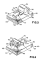
- a second embodiment of the electrical connector housing of the subject invention is identified generally by the numeral 60 in FIGS. 3 and 4.
- the housing 60 comprises a surface 62 extending generally orthogonal to the mating end 63 thereof.
- a plurality of terminal receiving cavities 64 extend from the mating end of the housing 60 to the conductor receiving end 65 thereof.
- a latch structure 70 is deflectably cantilevered from the surface 62 of housing 60 and is unitary therewith.
- the latch structure 70 comprises a base 74 generally adjacent the mating end 63 of the housing 60.
- a deflectable arm 76 extends from the base 74 and includes a locking protrusion 78 on the side thereof generally opposite the surface 62.
- the locking protrusion 78 includes a ramped forward surface 80 and a locking rear surface 82 which is aligned generally orthogonal to the surface 62 of housing 60.
- a depressible release actuator 84 is disposed at a location along the latch structure 70 remote from the base 74 thereof, such that the locking protrusion 78 is intermediate the base 74 and the depressible release actuator 84. Thus, a force exerted on the depressible release actuator 84 will deflect the latch structure 70 toward the surface 62 of housing 60.
- the housing 60 further comprises a pair of anti-fishhook arms 86 and 88 which are molded unitarily with the housing 60 to extend generally orthogonal to the surface 62 at a location generally in line with the rear end 90 of the latch structure 70. As described with the previous embodiment, the anti-fishhook arms 86 and 88 positively prevent a conductive lead from being engaged or fishhooked by the latch structure 70.
- the housing 60 further comprises an anti-overstress bar 92 extending unitarily between the anti-fishhook ribs 86 and 88. The anti-overstress bar 92 is disposed at a location to engage the latch structure 70 for preventing excessive deflection or overstress of the latch structure 70 away from the surface 62 of the housing 60.
- the latch structure 70 is provided with a ledge 94 at the end 90 thereof.
- the ledge 94 is disposed to engage the anti-overstress bar 92 to thereby prevent any excessive deflection of the latch structure 70 away from the surface 62.
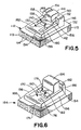
- FIG. 5 A third embodiment of the electrical connector housing of the subject invention is illustrated in FIG. 5 and is identified generally by the numeral 112.
- the housing 112 depicted in FIG. 5 is structurally and func tionally similar to the nonconductive housing 12 depicted in FIGS. 1 and 2. More particularly, the housing 112 comprises a mating end 113 with a plurality of cavities 114 extending therein. The cavities 114 extend from the mating end 113 to the opposed connector engaging end 115 and are provided with electrical terminals (not shown) securely mounted therein.
- the latch structure shown in FIG. 5 has been identified generally by the numeral 130.
- the latch structure 130 is deflectably cantilevered from the surface 132 at base 134.
- the latch structure 130 further comprises a deflectable arm portion 136 with a locking protrusion 138 having a ramped forward surface 140 and a locking rearward surface 142.
- a depressible release actuator 144 is disposed on the latch structure 130 at a location remote from the base 134 from which the latch structure 130 is cantilevered. Thus, a downward force on the depressible release actuator 144 will cause the latch 130 to deflect toward the surface 132 to facilitate the disengagement of the housing 112 from a mateable female housing as explained above.
- the housing 112 further comprises anti-fishhook ribs 146 and 148 disposed in spaced relationship to the cantilevered deflectable latch structure 130 and on opposite sides thereof.
- the anti-fishhook ribs 146 and 148 are disposed generally in line with the end 150 of the latch structure 130 to prevent the latch structure 130 from snagging or fishhooking conductive leads used in proximity to the housing 112.
- Anti-overstress arms 152 and 154 extend toward one another from the ends of the anti-fishhook ribs 146 and 148 respectively.
- the anti-overstress arms 152 and 154 are disposed to engage ledges 156 and 158 of the latch structure 130 to prevent overdeflection of the latch structure 130 away from the surface 132 of housing 112.
- the housing 112 differs from the housing 12 described above in that it is provided with side walls 160 and 162 which extend generally parallel to the latch structure 130 and in spaced relationship thereto. More particularly, the side walls 160 and 162 extend unitarily between the base 134 of the cantilevered latch structure 130 and the anti-fishhook ribs 146 and 148. The side walls 160 and 162 define a height measured from the surface 132 which substantially corresponds to the undeflected height of the cantilevered latch structure 130. Thus, the side walls 160 and 162 provide additional protection to the latch structure 130 and 132 from contact on the respective sides of the latch structure 130. As a result, the housing 112 depicted in FIG.
- the side walls 160 and 162 provide further assurance that adjacent conductive leads or the like will not inadvertently become engaged intermediate the cantilevered latch structure 130 and the surface 132. Thus the side walls 160 and 162 prevent overstress in the latch structure 130 and simultaneously prevent certain types of fishhooking beneath the latch structure 130.
- FIGS. 6 and 7 A fourth embodiment of the electrical connector housing of the subject invention is illustrated in FIGS. 6 and 7 and is identified generally by the numeral 164.
- the housing 164 depicted in FIGS. 6 and 7 is similar to the housing 60 depicted in FIGS. 3 and 4.
- the housing 164 is provided with a latch structure 170 cantilevered from surface 166 at base 174.
- the latch structure 170 comprises a deflectable arm portion 176 having a locking protrusion 178 extending from the side thereof opposite the surface 166.
- the locking protrusion comprises a ramped forward surface 180 and a rearward locking surface 182.
- a depressible release actuator 184 is disposed at a location along the latch structure 170 remote from the base 174 thereof.
- Anti-fishhook ribs 186 and 188 extend unitarily from the surface 166 at locations generally in line with the end 190 of the latch structure 170.
- An anti-overstress bar 192 extends unitarily between the anti-fishhook ribs 186 and 188 and is engageable with a ledge 194 disposed generally adjacent the end 190 of the latch structure 170. In particular, the anti-overstress bar 192 will engage the ledge 194 of the locking structure 170 to prevent overstress of the latch structure 170.
- the electrical connector housing 164 depicted in FIGS. 6 and 7 differs from the housing 160 of FIGS. 3 and 4 in that side walls 196 and 198 are provided on the housing 164 in a manner similar to the side walls 160 and 162 shown on the housing 112 of FIG. 5.
- the side walls 196 and 198 extend from the respective anti-fishhook ribs 186 and 188 to the base 174 of the latch structure 170.
- the side walls 196 and 198 extend from the surface 166 of the housing 164 a distance substantially corresponding to the height of the latch structure 170 from surface 166.
- the side walls 196 and 198 substantially minimize the possibility of a damaging contact with a side of the latch structure 170.
- any such contact that may occur, for example, on the depressible actuator 184 will cause only a minimal transverse deflection of the latch structure 170.
- the side walls substantially prevent leads from being extended into the area between the latch structure 170 and the top surface 166, thereby providing additional anti-fishhook protection to the housing 164, and ensuring that the latch structure 170 will operate under virtually all conditions.
- FIGS. 8-10 A fifth embodiment of the electrical connector housing of the subject invention is illustrated in FIGS. 8-10 and is identified generally by the numeral 200.
- the electrical connector housing 200 comprises a mating end 202 and an opposed conductor receiving end 204 with a plurality of terminal receiving cavities 206 extending therebetween.
- the housing 202 further comprises a unitarily molded latch structure 210 which extends from a planar top surface 212. More particularly, the latch structure 210 comprises a base 214 which extends unitarily from the top surface 212. A deflectable arm portion 216 extends from the base 214 generally toward the rear conductor receiving end 204 of the housing 200.
- the deflectable arm portion 216 of the latch structure 210 is provided with a locking protrusion 218 having a ramped forward surface 220 and a locking rearward surface 222 which is aligned approximately orthogonal to the top surface 212 of the electrical connector housing 200 in the undeflected condition of the latch structure 210.
- the latch structure 210 further comprises a depressible release actuator 224 disposed generally at the end of the latch structure 210 remote from the base 214. As shown in FIGS. 8-10 the locking protrusion 218 of the latch structure 210 is disposed intermediate the base 214 thereof and the release actuator 224. By virtue of this construction, a downward pressure on the release actuator 224 toward the surface 212 will deflect the latch structure 210 and enable disengagement of the locking protrusion 218 from a corresponding locking structure on a mateable female connector housing (not shown).
- the deflectable latch structure 210 is not of cantilevered construction. Rather, the electrical connector housing 200 is provided with anti-fishhook ribs 226 and 228 which extend unitarily from the surface 212, and which are unitarily connected to the end of the latch structure 210 remote from the base 214. As a result of this construction, the ribs 226 and 228 simultaneously perform an anti-fishhooking function and an anti-overstressing function. In particular, the ribs 226 and 228 positively prevent any conductive leads or the like from being fishhooked by the latch structure 210 and trapped between the latch structure 210 and the surface 212 of the housing 200. Furthermore, the ribs 226 and 228 prevent overstress rotation of the latch structure 210 away from the surface 212 of the housing 200. In this manner, overstress damage to the latch structure 210 is prevented.
- FIGS. 11 and 12 A variation of the electrical connector housing 200 depicted in FIGS. 8-10 is shown in FIGS. 11 and 12 and is identified generally by the numeral 230.
- the electrical connector housing 230 comprises a mating end 232 and an opposed conductor receiving end 234.
- a plurality of terminal receiving recesses 236 extend between the opposed ends 232 and 234 and are provided with electrically conductive terminals securely mounted therein and engageable with a mateable female electrical connector (not shown).
- a latch structure 240 extends unitarily from the top surface 242 of the housing 230. More particularly, the latch structure 240 comprises a base 244 which extends unitarily from the top surface 242 of the housing 230. The latch structure 240 further comprises a deflectable arm portion 246 having a locking protrusion 248 extending therefrom. As with the previously described embodiments, the locking protrusion 248 includes a forwardly facing ramp surface 250 and a rearwardly facing locking surface 252. A depressible release actuator 254 is disposed generally at the end of the deflectable latch structure 240 remote from the base 244 thereof.
- the electrical connector housing 230 further comprises a pair of ribs 256 and 258 which extend unitarily between the top surface 242 of the electrical connector housing 230 and the end of the latch structure 240 remote from the base 244 thereof.
- the latch structure 240 is not truly cantilevered, but rather is deflectable between the supports at opposed ends thereof.
- the ribs 256 and 258 simultaneously prevent fishhooking of conductive leads or the like by the latch structure 240, and also prevent overstress of the latch structure 240 relative to its initial undeflected position as shown in FIGS. 11 and 12.
- the electrical connector housing 230 depicted in FIGS. 11 and 12 generally follows the construction of embodiments depicted in FIGS. 5-7. More particularly, the electrical connector housing 230 comprises side walls 266 and 268 which are disposed in spaced generally parallel relationship to the latch structure 240 and on opposite sides thereof. In particular, the side walls 266 and 268 extend unitarily between the respective ribs 256 and 258 and the base 244 of the latch structure 240. The side walls 266 and 268 extend to a height substantially corresponding to the undeflected height of the latch structure 240 from the top surface 242 of the electrical connector housing 230. Thus, as with the embodiments depicted in FIGS.
- the side walls 266 and 268 substantially eliminate the possibility of transverse contact with a side of the latch structure 240 and further minimize the magnitude of any transverse deflection of the latch structure 240. Additionally, the presence of the side walls 266 and 268 adjacent the latch structure 240 substantially prevents any electrical conductor or other circuit component from being engaged intermediate the latch structure 240 and the surface 242 of the electrical connector housing 230.
- an electrical connector housing is provided with a latch structure that positively prevents overstressing and fishhooking.
- the electrical connector housing comprises a deflectable latch structure extending from one surface thereof.
- At least one anti-fishhook rib extends from the electrical connector housing in proximity to the deflectable end of the latch structure.
- the anti-fishhook rib prevents conductive leads or the like from being engaged intermediate the deflectable latch structure and the opposed facing surface of the electrical connector housing.
- the anti-fishhook rib is constructed to engage the latch structure and prevent overstress or overdeflection of the latch structure.
- a pair of such anti-fishhooking ribs and corresponding anti-overstress arms may be provided on opposed respective sides of the latch structure.
- the electrical connector housing may further comprise side walls disposed in spaced generally parallel relationship to the deflectable latch structure for further preventing overstress and for further preventing the fishhooking of conductive leads or the like into the space between the deflectable latch structure and the opposed facing wall of the electrical connector housing.
- the connector housings that positively prevent latch structures of the housings from being entangled with insulated conductive leads employed in the vicinity of the connectors.
- the connector housings are of simple integrally molded construction which prevents overstress of the latch structures thereof and which prevents fishhooking of insulated conductive leads.
- the housings furthermore, cannot easily be damaged accidentally during initial harness work, handling or subsequent use.
Landscapes
- Details Of Connecting Devices For Male And Female Coupling (AREA)
Applications Claiming Priority (2)
| Application Number | Priority Date | Filing Date | Title |
|---|---|---|---|
| US23298588A | 1988-08-17 | 1988-08-17 | |
| US232985 | 1988-08-17 |
Publications (3)
| Publication Number | Publication Date |
|---|---|
| EP0356157A2 true EP0356157A2 (fr) | 1990-02-28 |
| EP0356157A3 EP0356157A3 (en) | 1990-11-22 |
| EP0356157B1 EP0356157B1 (fr) | 1995-01-25 |
Family
ID=22875396
Family Applications (1)
| Application Number | Title | Priority Date | Filing Date |
|---|---|---|---|
| EP19890308379 Expired - Lifetime EP0356157B1 (fr) | 1988-08-17 | 1989-08-17 | Connecteur électrique ayant un loquet antisurcharge |
Country Status (3)
| Country | Link |
|---|---|
| EP (1) | EP0356157B1 (fr) |
| JP (1) | JPH02112180A (fr) |
| DE (1) | DE68920799T2 (fr) |
Cited By (10)
| Publication number | Priority date | Publication date | Assignee | Title |
|---|---|---|---|---|
| EP0503661A2 (fr) * | 1991-03-13 | 1992-09-16 | Yazaki Corporation | Connecteur |
| EP0643446A1 (fr) * | 1993-09-10 | 1995-03-15 | CONNECTEURS CINCH, Société Anonyme dite : | Perfectionnements aux boîtiers de connecteurs électriques |
| EP0729202A2 (fr) * | 1995-02-24 | 1996-08-28 | Sumitomo Wiring Systems, Ltd. | Mécanisme de verrouillage pour boîtier de connecteur |
| WO1998024151A1 (fr) * | 1996-11-29 | 1998-06-04 | The Whitaker Corporation | Element de verrouillage elastique pour connecteur electrique |
| EP0926773A1 (fr) * | 1997-12-25 | 1999-06-30 | Sumitomo Wiring Systems, Ltd. | Connecteur ayant un couvercle |
| GB2338124A (en) * | 1998-04-29 | 1999-12-08 | Static Systems Group Plc | A plug and socket |
| WO2000036709A2 (fr) * | 1998-12-17 | 2000-06-22 | Richard Drewnicki | Connecteurs electriques |
| EP1601063A1 (fr) * | 2004-05-19 | 2005-11-30 | Sumitomo Wiring Systems, Ltd. | Dispositif de raccordement |
| WO2010136832A3 (fr) * | 2006-07-19 | 2011-01-20 | Molex Incorporated | Connecteur à levier |
| CN107425377A (zh) * | 2016-05-12 | 2017-12-01 | 莫列斯有限公司 | 连接器 |
Families Citing this family (9)
| Publication number | Priority date | Publication date | Assignee | Title |
|---|---|---|---|---|
| JPH03112887U (fr) * | 1990-03-01 | 1991-11-19 | ||
| JPH11185874A (ja) * | 1997-12-19 | 1999-07-09 | Yazaki Corp | コネクタのロックアーム保護構造 |
| JP3561143B2 (ja) | 1998-04-02 | 2004-09-02 | 矢崎総業株式会社 | ロック構造 |
| JP3826799B2 (ja) * | 2001-03-02 | 2006-09-27 | 住友電装株式会社 | コネクタ |
| JP6410166B2 (ja) * | 2014-04-18 | 2018-10-24 | パナソニックIpマネジメント株式会社 | コネクタおよびコネクタ装置 |
| JP2016110851A (ja) * | 2014-12-08 | 2016-06-20 | 矢崎総業株式会社 | コネクタ |
| JP6401676B2 (ja) | 2015-08-06 | 2018-10-10 | モレックス エルエルシー | コネクタ及びコネクタ組立体 |
| JP6953191B2 (ja) * | 2017-06-06 | 2021-10-27 | 矢崎総業株式会社 | コネクタ、及び、ワイヤハーネス |
| JP7425973B2 (ja) * | 2020-12-09 | 2024-02-01 | 住友電装株式会社 | コネクタ |
Citations (8)
| Publication number | Priority date | Publication date | Assignee | Title |
|---|---|---|---|---|
| US3179738A (en) * | 1962-11-07 | 1965-04-20 | Amp Inc | Electrical connector housing having panel mounting and latching means |
| US4105275A (en) * | 1977-08-18 | 1978-08-08 | E. I. Du Pont De Nemours And Company | Header with integral latch members |
| EP0006183A1 (fr) * | 1978-06-12 | 1980-01-09 | Magnetic Controls Company | Dispositif de verrouillage |
| EP0028120A1 (fr) * | 1979-10-22 | 1981-05-06 | Ford Motor Company Limited | Dispositif de déverrouillage pour connecteur |
| US4462654A (en) * | 1983-02-07 | 1984-07-31 | Amp Incorporated | Electrical connector housing with integral latch |
| EP0116426A1 (fr) * | 1983-02-09 | 1984-08-22 | AMP INCORPORATED (a New Jersey corporation) | Ensemble de connecteur électrique comprenant une barre d'éjection |
| WO1985005501A1 (fr) * | 1984-05-17 | 1985-12-05 | Amp Incorporated | Boitier de connecteur electrique |
| GB2177266A (en) * | 1985-06-27 | 1987-01-14 | Amp Inc | Electrical connector having integral latch means |
Family Cites Families (4)
| Publication number | Priority date | Publication date | Assignee | Title |
|---|---|---|---|---|
| JPS5465923A (en) * | 1977-11-07 | 1979-05-28 | Nissan Motor Co Ltd | Hydropneumatic suspension apparatus |
| JPS563900U (fr) * | 1979-06-19 | 1981-01-14 | ||
| JPS5650692U (fr) * | 1979-09-25 | 1981-05-06 | ||
| JPS5812158A (ja) * | 1981-07-15 | 1983-01-24 | Matsushita Electric Ind Co Ltd | 磁気テ−プ駆動装置 |
-
1989
- 1989-08-11 JP JP20952389A patent/JPH02112180A/ja active Pending
- 1989-08-17 DE DE1989620799 patent/DE68920799T2/de not_active Expired - Lifetime
- 1989-08-17 EP EP19890308379 patent/EP0356157B1/fr not_active Expired - Lifetime
Patent Citations (8)
| Publication number | Priority date | Publication date | Assignee | Title |
|---|---|---|---|---|
| US3179738A (en) * | 1962-11-07 | 1965-04-20 | Amp Inc | Electrical connector housing having panel mounting and latching means |
| US4105275A (en) * | 1977-08-18 | 1978-08-08 | E. I. Du Pont De Nemours And Company | Header with integral latch members |
| EP0006183A1 (fr) * | 1978-06-12 | 1980-01-09 | Magnetic Controls Company | Dispositif de verrouillage |
| EP0028120A1 (fr) * | 1979-10-22 | 1981-05-06 | Ford Motor Company Limited | Dispositif de déverrouillage pour connecteur |
| US4462654A (en) * | 1983-02-07 | 1984-07-31 | Amp Incorporated | Electrical connector housing with integral latch |
| EP0116426A1 (fr) * | 1983-02-09 | 1984-08-22 | AMP INCORPORATED (a New Jersey corporation) | Ensemble de connecteur électrique comprenant une barre d'éjection |
| WO1985005501A1 (fr) * | 1984-05-17 | 1985-12-05 | Amp Incorporated | Boitier de connecteur electrique |
| GB2177266A (en) * | 1985-06-27 | 1987-01-14 | Amp Inc | Electrical connector having integral latch means |
Cited By (22)
| Publication number | Priority date | Publication date | Assignee | Title |
|---|---|---|---|---|
| EP0503661A3 (en) * | 1991-03-13 | 1992-11-25 | Yazaki Corporation | Connector |
| US5203715A (en) * | 1991-03-13 | 1993-04-20 | Yazaki Corporation | Connector |
| EP0503661A2 (fr) * | 1991-03-13 | 1992-09-16 | Yazaki Corporation | Connecteur |
| EP0643446A1 (fr) * | 1993-09-10 | 1995-03-15 | CONNECTEURS CINCH, Société Anonyme dite : | Perfectionnements aux boîtiers de connecteurs électriques |
| FR2709884A1 (fr) * | 1993-09-10 | 1995-03-17 | Cinch Connecteurs Sa | Perfectionnements aux boîtiers de connecteurs électriques. |
| US5496190A (en) * | 1993-09-10 | 1996-03-05 | Connecteurs Cinch | Electrical connector casings |
| EP0729202A2 (fr) * | 1995-02-24 | 1996-08-28 | Sumitomo Wiring Systems, Ltd. | Mécanisme de verrouillage pour boîtier de connecteur |
| EP0729202A3 (fr) * | 1995-02-24 | 1997-09-10 | Sumitomo Wiring Systems | Mécanisme de verrouillage pour boîtier de connecteur |
| WO1998024151A1 (fr) * | 1996-11-29 | 1998-06-04 | The Whitaker Corporation | Element de verrouillage elastique pour connecteur electrique |
| US6135802A (en) * | 1997-12-25 | 2000-10-24 | Sumitomo Wiring Systems, Ltd. | Cover-equipped connector |
| EP0926773A1 (fr) * | 1997-12-25 | 1999-06-30 | Sumitomo Wiring Systems, Ltd. | Connecteur ayant un couvercle |
| GB2338124A (en) * | 1998-04-29 | 1999-12-08 | Static Systems Group Plc | A plug and socket |
| GB2338124B (en) * | 1998-04-29 | 2002-08-21 | Static Systems Group Plc | A releasable plug |
| WO2000036709A3 (fr) * | 1998-12-17 | 2000-09-14 | Richard Drewnicki | Connecteurs electriques |
| WO2000036709A2 (fr) * | 1998-12-17 | 2000-06-22 | Richard Drewnicki | Connecteurs electriques |
| GB2361366A (en) * | 1998-12-17 | 2001-10-17 | Richard Drewnicki | Electrical connectors |
| EP1601063A1 (fr) * | 2004-05-19 | 2005-11-30 | Sumitomo Wiring Systems, Ltd. | Dispositif de raccordement |
| WO2010136832A3 (fr) * | 2006-07-19 | 2011-01-20 | Molex Incorporated | Connecteur à levier |
| CN102160244A (zh) * | 2006-07-19 | 2011-08-17 | 莫列斯公司 | 具有杠杆的连接器 |
| CN102160244B (zh) * | 2006-07-19 | 2013-10-23 | 莫列斯公司 | 具有杠杆的连接器 |
| CN107425377A (zh) * | 2016-05-12 | 2017-12-01 | 莫列斯有限公司 | 连接器 |
| CN107425377B (zh) * | 2016-05-12 | 2020-09-25 | 莫列斯有限公司 | 连接器 |
Also Published As
| Publication number | Publication date |
|---|---|
| EP0356157B1 (fr) | 1995-01-25 |
| DE68920799T2 (de) | 1995-09-07 |
| EP0356157A3 (en) | 1990-11-22 |
| DE68920799D1 (de) | 1995-03-09 |
| JPH02112180A (ja) | 1990-04-24 |
Similar Documents
| Publication | Publication Date | Title |
|---|---|---|
| US4986766A (en) | Electrical connector having anti-overstress latch | |
| EP0356157A2 (fr) | Connecteur électrique ayant un loquet antisurcharge | |
| US5713752A (en) | Latchable electrical connector | |
| EP1932219B1 (fr) | Fiche modulaire dotee d un element de verrouillage coulissant | |
| EP0966067B1 (fr) | Connecteur à levier de verrouillage | |
| US6217364B1 (en) | Electrical connector assembly with guide pin latching system | |
| US4335931A (en) | Power cable connector with retention spring | |
| EP1978606B1 (fr) | Connecteur pour montage sur panneau à verrou coulissant | |
| EP0805523A2 (fr) | Système de verrouillage pour connecteurs électriques | |
| EP0288249A1 (fr) | Levier à ressort pour verrouiller ensemble des connecteurs électriques | |
| JPH0628191B2 (ja) | 電気コネクタ−組立体 | |
| EP0382344B1 (fr) | Verrouillage renforcé de connecteur | |
| US5928027A (en) | Electrical connector system for a flat flexible circuit | |
| JP2018120686A (ja) | コネクタ | |
| WO2005048413A1 (fr) | Verrou pour connecteur electrique | |
| EP0929125B1 (fr) | Verrouillage de connecteur avec charnière de forme tubulaire | |
| US4406511A (en) | Flat cable connector strain relief | |
| CA2646151C (fr) | Ensemble d'embase | |
| KR100198409B1 (ko) | 자체 로킹 결합 단자 구조 | |
| US5154630A (en) | Plug connector assembly | |
| EP0115425A2 (fr) | Assemblage connecteur à système de verrouillage interne | |
| EP0452059A1 (fr) | Connecteur électrique à verrouillage | |
| US5427549A (en) | Electrical cable assembly with improved latch | |
| US6638096B1 (en) | Electrical connector having improved latching mechanism | |
| US20060110969A1 (en) | Cable assembly having improved latch |
Legal Events
| Date | Code | Title | Description |
|---|---|---|---|
| PUAI | Public reference made under article 153(3) epc to a published international application that has entered the european phase |
Free format text: ORIGINAL CODE: 0009012 |
|
| AK | Designated contracting states |
Kind code of ref document: A2 Designated state(s): DE FR GB IT NL SE |
|
| PUAL | Search report despatched |
Free format text: ORIGINAL CODE: 0009013 |
|
| AK | Designated contracting states |
Kind code of ref document: A3 Designated state(s): DE FR GB IT NL SE |
|
| 17P | Request for examination filed |
Effective date: 19910507 |
|
| 17Q | First examination report despatched |
Effective date: 19930816 |
|
| GRAA | (expected) grant |
Free format text: ORIGINAL CODE: 0009210 |
|
| ITF | It: translation for a ep patent filed |
Owner name: BARZANO' E ZANARDO MILANO S.P.A. |
|
| AK | Designated contracting states |
Kind code of ref document: B1 Designated state(s): DE FR GB IT NL SE |
|
| REF | Corresponds to: |
Ref document number: 68920799 Country of ref document: DE Date of ref document: 19950309 |
|
| ET | Fr: translation filed | ||
| PLBE | No opposition filed within time limit |
Free format text: ORIGINAL CODE: 0009261 |
|
| STAA | Information on the status of an ep patent application or granted ep patent |
Free format text: STATUS: NO OPPOSITION FILED WITHIN TIME LIMIT |
|
| 26N | No opposition filed | ||
| REG | Reference to a national code |
Ref country code: GB Ref legal event code: IF02 |
|
| PGFP | Annual fee paid to national office [announced via postgrant information from national office to epo] |
Ref country code: SE Payment date: 20030805 Year of fee payment: 15 |
|
| PG25 | Lapsed in a contracting state [announced via postgrant information from national office to epo] |
Ref country code: SE Free format text: LAPSE BECAUSE OF NON-PAYMENT OF DUE FEES Effective date: 20040818 |
|
| EUG | Se: european patent has lapsed | ||
| PGFP | Annual fee paid to national office [announced via postgrant information from national office to epo] |
Ref country code: NL Payment date: 20080824 Year of fee payment: 20 |
|
| PGFP | Annual fee paid to national office [announced via postgrant information from national office to epo] |
Ref country code: FR Payment date: 20080818 Year of fee payment: 20 Ref country code: IT Payment date: 20080827 Year of fee payment: 20 |
|
| PGFP | Annual fee paid to national office [announced via postgrant information from national office to epo] |
Ref country code: GB Payment date: 20080827 Year of fee payment: 20 |
|
| PGFP | Annual fee paid to national office [announced via postgrant information from national office to epo] |
Ref country code: DE Payment date: 20080930 Year of fee payment: 20 |
|
| REG | Reference to a national code |
Ref country code: GB Ref legal event code: PE20 Expiry date: 20090816 |
|
| NLV7 | Nl: ceased due to reaching the maximum lifetime of a patent |
Effective date: 20090817 |
|
| PG25 | Lapsed in a contracting state [announced via postgrant information from national office to epo] |
Ref country code: NL Free format text: LAPSE BECAUSE OF EXPIRATION OF PROTECTION Effective date: 20090817 Ref country code: GB Free format text: LAPSE BECAUSE OF EXPIRATION OF PROTECTION Effective date: 20090816 |