EP0354204A2 - Optischer Sensor und Verfahren zu dessen Herstellung - Google Patents
Optischer Sensor und Verfahren zu dessen Herstellung Download PDFInfo
- Publication number
- EP0354204A2 EP0354204A2 EP89890202A EP89890202A EP0354204A2 EP 0354204 A2 EP0354204 A2 EP 0354204A2 EP 89890202 A EP89890202 A EP 89890202A EP 89890202 A EP89890202 A EP 89890202A EP 0354204 A2 EP0354204 A2 EP 0354204A2
- Authority
- EP
- European Patent Office
- Prior art keywords
- layer
- carrier particles
- optical sensor
- polymer film
- sensor according
- Prior art date
- Legal status (The legal status is an assumption and is not a legal conclusion. Google has not performed a legal analysis and makes no representation as to the accuracy of the status listed.)
- Granted
Links
Images
Classifications
-
- G—PHYSICS
- G01—MEASURING; TESTING
- G01N—INVESTIGATING OR ANALYSING MATERIALS BY DETERMINING THEIR CHEMICAL OR PHYSICAL PROPERTIES
- G01N21/00—Investigating or analysing materials by the use of optical means, i.e. using sub-millimetre waves, infrared, visible or ultraviolet light
- G01N21/62—Systems in which the material investigated is excited whereby it emits light or causes a change in wavelength of the incident light
- G01N21/63—Systems in which the material investigated is excited whereby it emits light or causes a change in wavelength of the incident light optically excited
- G01N21/64—Fluorescence; Phosphorescence
- G01N21/6428—Measuring fluorescence of fluorescent products of reactions or of fluorochrome labelled reactive substances, e.g. measuring quenching effects, using measuring "optrodes"
- G01N21/643—Measuring fluorescence of fluorescent products of reactions or of fluorochrome labelled reactive substances, e.g. measuring quenching effects, using measuring "optrodes" non-biological material
-
- C—CHEMISTRY; METALLURGY
- C12—BIOCHEMISTRY; BEER; SPIRITS; WINE; VINEGAR; MICROBIOLOGY; ENZYMOLOGY; MUTATION OR GENETIC ENGINEERING
- C12Q—MEASURING OR TESTING PROCESSES INVOLVING ENZYMES, NUCLEIC ACIDS OR MICROORGANISMS; COMPOSITIONS OR TEST PAPERS THEREFOR; PROCESSES OF PREPARING SUCH COMPOSITIONS; CONDITION-RESPONSIVE CONTROL IN MICROBIOLOGICAL OR ENZYMOLOGICAL PROCESSES
- C12Q1/00—Measuring or testing processes involving enzymes, nucleic acids or microorganisms; Compositions therefor; Processes of preparing such compositions
- C12Q1/001—Enzyme electrodes
-
- G—PHYSICS
- G01—MEASURING; TESTING
- G01N—INVESTIGATING OR ANALYSING MATERIALS BY DETERMINING THEIR CHEMICAL OR PHYSICAL PROPERTIES
- G01N31/00—Investigating or analysing non-biological materials by the use of the chemical methods specified in the subgroup; Apparatus specially adapted for such methods
- G01N31/22—Investigating or analysing non-biological materials by the use of the chemical methods specified in the subgroup; Apparatus specially adapted for such methods using chemical indicators
- G01N31/223—Investigating or analysing non-biological materials by the use of the chemical methods specified in the subgroup; Apparatus specially adapted for such methods using chemical indicators for investigating presence of specific gases or aerosols
-
- G—PHYSICS
- G01—MEASURING; TESTING
- G01N—INVESTIGATING OR ANALYSING MATERIALS BY DETERMINING THEIR CHEMICAL OR PHYSICAL PROPERTIES
- G01N21/00—Investigating or analysing materials by the use of optical means, i.e. using sub-millimetre waves, infrared, visible or ultraviolet light
- G01N21/62—Systems in which the material investigated is excited whereby it emits light or causes a change in wavelength of the incident light
- G01N21/63—Systems in which the material investigated is excited whereby it emits light or causes a change in wavelength of the incident light optically excited
- G01N21/64—Fluorescence; Phosphorescence
- G01N21/6428—Measuring fluorescence of fluorescent products of reactions or of fluorochrome labelled reactive substances, e.g. measuring quenching effects, using measuring "optrodes"
- G01N2021/6434—Optrodes
-
- G—PHYSICS
- G01—MEASURING; TESTING
- G01N—INVESTIGATING OR ANALYSING MATERIALS BY DETERMINING THEIR CHEMICAL OR PHYSICAL PROPERTIES
- G01N21/00—Investigating or analysing materials by the use of optical means, i.e. using sub-millimetre waves, infrared, visible or ultraviolet light
- G01N21/75—Systems in which material is subjected to a chemical reaction, the progress or the result of the reaction being investigated
- G01N21/77—Systems in which material is subjected to a chemical reaction, the progress or the result of the reaction being investigated by observing the effect on a chemical indicator
- G01N21/78—Systems in which material is subjected to a chemical reaction, the progress or the result of the reaction being investigated by observing the effect on a chemical indicator producing a change of colour
- G01N21/80—Indicating pH value
-
- Y—GENERAL TAGGING OF NEW TECHNOLOGICAL DEVELOPMENTS; GENERAL TAGGING OF CROSS-SECTIONAL TECHNOLOGIES SPANNING OVER SEVERAL SECTIONS OF THE IPC; TECHNICAL SUBJECTS COVERED BY FORMER USPC CROSS-REFERENCE ART COLLECTIONS [XRACs] AND DIGESTS
- Y10—TECHNICAL SUBJECTS COVERED BY FORMER USPC
- Y10S—TECHNICAL SUBJECTS COVERED BY FORMER USPC CROSS-REFERENCE ART COLLECTIONS [XRACs] AND DIGESTS
- Y10S435/00—Chemistry: molecular biology and microbiology
- Y10S435/817—Enzyme or microbe electrode
Definitions
- the invention relates to an optical sensor for determining at least one parameter in a liquid or gaseous sample, with a carrier layer which has carrier particles with a fluorescence indicator immobilized thereon, and a method for its production.
- Optical measurement e.g. of the pH of liquid samples
- electrochemical methods e.g. with the help of the glass electrode
- optical pH sensors do not require a reference cell and, in combination with thin, fiber-optic light guides, can also be used for invasive measurements in the body.
- optical pH sensors are known from the literature. A distinction is made in principle between two types of sensors, namely those that are first manufactured and then attached to the end of an optical fiber, so-called planar sensors, or fiber sensors of the first type, and those that are manufactured directly by modifying the optical fiber, so-called fiber sensors of the second type.
- a typical sensor of the first type is described, for example, in Anal. Chem. 52, 864 (1980), where a pH-sensitive Ma material, which is arranged at the end of a light guide, is used for inversive measurement of blood pH values.
- the sensitive material is obtained by soaking polystyrene beads with an indicator solution.
- the attachment at the end of the light guide is done by filling a thin cellophane tube, which is pulled over the light guide, with the polystyrene beads.
- a pH sensor is known from US Pat. No. 3,904,373, which contains dye indicators based on light absorption covalently bound to carrier materials.
- the fluorescent indicators are bound to the carrier materials with functional triethoxysilanes.
- Sintered glass particles, etched glass and CPG powder (controlled porous glass) act as carrier materials.
- CPG is also only suitable to a limited extent, since when CPG powder is sintered together, its microporous structure is lost.
- the object of the invention is to propose an optical sensor and a method for its production, which can also be produced in large numbers in a simple manner, reacts to the changing parameters of the sample with a short response time and has a large effective surface area points, and that the fluorescence indicator is present in quasi-aqueous solution instead of bound to hydrophobic materials.
- the carrier layer consists of a polymer film that is permeable to the excitation and emission radiation, that the individual carrier particles with the fluorescence indicator immobilized thereon are fixed only with a part of their surface in a layer of a thermoplastic material that adheres to the polymer film , which assumes thermosetting properties after the carrier particles have been pressed in, and with the other part of its surface immerse in an optically permeable hydrogel layer covering the adhesive layer, which adheres to the carrier particles by clawing.
- thermoplastic material is applied as a thin adhesive layer to an optically permeable polymer film, that carrier particles with a fluorescent indicator immobilized thereon are applied in a uniform distribution and partially pressed into the adhesive layer by thermal compression molding and mechanically fixed by the latter, and that a hydrogel layer covering the adhesive layer and receiving the free parts of the individual carrier particles is applied.
- the individual carrier particles are therefore not penetrated by an adhesive, but are pressed into an adhesive layer by applying pressure and are only mechanically fixed there.
- the fluorescence indicator immobilized on the carrier particle is freely accessible via the hydrogel layer in practically all areas for the substances to be measured from the sample.
- a particularly advantageous embodiment of the invention provides that the carrier particles consist of individual fibers which are fixed with a small part of their surface in the layer adhering to the polymer film and are immersed in the hydrogel layer with most of their surface.
- the carrier particles consist of individual fibers which are fixed with a small part of their surface in the layer adhering to the polymer film and are immersed in the hydrogel layer with most of their surface.
- fibrous carrier material it can be achieved that only a small part of the surface is fixed in the adhesive layer and the largest part of the fibers in the Hy layer of drug is sufficient and also binds it mechanically to the adhesive layer.
- the carrier particles consist of silica gel beads with an irreversibly bound fluorescence indicator, of microporous glass beads or of polyacrylamide. CPG beads or polyamide particles are suitable for this.
- a sensor is created in which the fiber diameter or the diameter of the individual carrier particles is greater than the thickness of the layer adhering to the polymer film.
- the hydrogel layer can be covered by a pigmented or colored hydrogel layer in a further step in order to achieve optical isolation, for example to shield ambient light, scattered light or fluorescent light from the sample.
- a pigmented or colored hydrogel layer in a further step in order to achieve optical isolation, for example to shield ambient light, scattered light or fluorescent light from the sample.
- activated carbon, iron oxide powder or titanium dioxide powder can be used.
- a pH-sensitive fluorescence indicator is immobilized on the carrier particles.
- a CO2-permeable, ion-impermeable membrane and a CO2-sensitive fluorescence indicator can be provided for measuring the CO2 partial pressure.
- the CO2 partial pressure can be measured via changes in the internal pH.
- the sensor can be covered with a silicone-polycarbonate film.
- an O2-permeable, ion-impermeable membrane and an O2-sensitive fluorescence indicator are provided for the measurement of oxygen.
- an optical enzyme sensor is also conceivable if an enzyme from the group of hydrolases, oxidases and dehydrogenases is immobilized on the carrier particles or in the hydrogel layer.
- the adhesive layer, the carrier particles together with the immobilized fluorescent indicator, the hydrogel layer and, if appropriate, the CO2- or O2-permeable, ion-impermeable membrane are applied over a large area to a polymer film and a large number of similar sensors are punched out in one operation. Since all materials used can be punched or cut, sensors of any shape and size can be easily manufactured.
- a special embodiment of the sensor according to the invention provides that the fibers consist of microcrystalline cellulose fibers with a covalently immobilized fluorescent indicator, the individual cellulose fibers according to the invention having a diameter of 5 to 10 ⁇ m, preferably approx. 8 ⁇ m and a length of 50 to 200 ⁇ m, preferably have about 80 microns.
- planar optical sensors produced in this way which can be very easily attached to the end of a light guide or light guide bundle, are distinguished in that the polymer film has a thickness of 20 to 500 ⁇ m, the layer adhering to it a thickness of 5 to 10 ⁇ m and the individual hydrogel layers have a thickness of 5 to 30 microns.
- optical isolation which is often required to suppress false light, is an integral part of the sensor layer, whereas with other types of sensor it has to be mechanically attached in a separate operation.
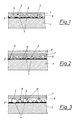
- a pH sensor which has a polymer film 1, for example a mylar film which is transparent to the excitation and emission radiation, with a thickness of 175 ⁇ m as the carrier layer.
- a layer 2 of a thermoplastically deformable material in which the individual fibers 3 with the fluorescence indicator immobilized thereon are pressed in with a part 4 of their surface and mechanically fixed.
- the major part 5 of the fibers 3 protrudes into a hydrogel layer 6 covering the adhesive layer 2, as a result of which the fluorescence indicator is present in a quasi-aqueous environment.
- the fibers 3 serve at the same time as immobilization carriers and for sufficient mechanical anchoring of the hydrogel layer 6 on the adhesive layer 2, which has a thickness which is smaller than the diameter of the individual cellulose fibers.
- a hydrogel layer 7 pigmented with activated carbon is arranged on the sample side.
- This layer is of course also suitable for all other substances which have become known in this connection.
- a CO2-permeable, ion-impermeable membrane 8 for example a silicone-polycarbonate copolymer film with a thickness of 1 mil.
- carrier particles 9 made of non-fibrous material are used.
- the carrier particles can consist, for example, of silica gel beads with a fluorescence indicator absorbed therein, of microporous glass beads (CPG) or of polyamide.
Landscapes
- Life Sciences & Earth Sciences (AREA)
- Chemical & Material Sciences (AREA)
- Health & Medical Sciences (AREA)
- Physics & Mathematics (AREA)
- Immunology (AREA)
- Biochemistry (AREA)
- Molecular Biology (AREA)
- Organic Chemistry (AREA)
- General Health & Medical Sciences (AREA)
- Analytical Chemistry (AREA)
- Wood Science & Technology (AREA)
- Engineering & Computer Science (AREA)
- General Physics & Mathematics (AREA)
- Pathology (AREA)
- Zoology (AREA)
- Biophysics (AREA)
- Proteomics, Peptides & Aminoacids (AREA)
- Optics & Photonics (AREA)
- Biotechnology (AREA)
- Microbiology (AREA)
- Dispersion Chemistry (AREA)
- Nuclear Medicine, Radiotherapy & Molecular Imaging (AREA)
- Chemical Kinetics & Catalysis (AREA)
- Bioinformatics & Cheminformatics (AREA)
- General Engineering & Computer Science (AREA)
- Genetics & Genomics (AREA)
- Investigating Or Analysing Materials By The Use Of Chemical Reactions (AREA)
- Investigating, Analyzing Materials By Fluorescence Or Luminescence (AREA)
- Investigating Or Analyzing Non-Biological Materials By The Use Of Chemical Means (AREA)
Abstract
Description
- Die Erfindung betrifft einen optischen Sensor zur Bestimmung zumindest eines Parameters in einer flüssigen oder gasförmigen Probe, mit einer Trägerschicht, welche Trägerpartikel mit einem daran immobilisierten Fluoreszenzindikator aufweist, sowie ein Verfahren zu dessen Herstellung.
- Die optische Messung, beispielsweise des pH-Wertes flüssiger Proben, hat in den letzten Jahren bedeutende Fortschritte gemacht, da sie gegenüber elektrochemischen Methoden, z.B. mit Hilfe der Glaselektrode, große Vorteile bietet. So benötigen optische pH-Sensoren keine Referenzzelle und können, in Kombination mit dünnen, faseroptischen Lichtleitern auch für invasive Messungen im Körper eingesetzt werden.
- Verschiedene optische pH-Sensoren sind aus der Literatur bekannt. Man unterscheidet prinzipiell zwischen zwei Arten von Sensoren, nämlich solchen, welche zuerst gefertigt und dann am Ende eines Lichtleiters angebracht werden, sogenannte planare Sensoren, oder Fasersensoren erster Art, und solchen, welche direkt durch Modifikation des Lichtleiters hergestellt werden, sogenannte Fasersensoren zweiter Art.
- Die Herstellung letztgenannter Sensoren, die nicht Gegenstand dieser Erfindung sind, ist zwar zum Teil eleganter, aber mit technischen Schwierigkeiten verbunden, besonders was eine reproduzierbare Herstellung betrifft. Aus diesem Grund werden für die Massenfertigung eher planare Sensoren bevorzugt.
- Ein typischer Sensor der ersten Art ist beispielsweise in Anal.Chem.52, 864 (1980) beschrieben, wo ein pH-sensitives Ma terial, welches am Ende eines Lichtleiters angeordnet ist, zur inversiven Messung von Blut- pH-Werten herangezogen wird. Das sensitive Material wird durch Tränken von Polystyrol-Kügelchen mit einer Indikatorlösung erhalten. Die Befestigung am Ende des Lichtleiters erfolgt durch Füllen eines dünnen, über den Lichtleiter gezogenen Cellophanschlauches mit den Polystyrol-Kügelchen.
- Es ist auch möglich, einen Indikator direkt auf eine Membran oder die Oberfläche eines festen Trägers, wie z.B. Glas, aufzubringen. Beispielsweise wird in Sensor and Actuators 9, 73 (1986) von H. Offenbacher et. al. eine Methode zur Immobilisierung von pH-Indikatoren auf Glas, welches am Ende eines Lichtleiters angebracht wird, vorgeschlagen.
- Des weiteren ist aus der US-PS 3 904 373 ein pH-Sensor bekannt, welcher Farbstoffindikatoren auf Lichtabsorptionsbasis kovalent an Trägermaterialien gebunden enthält. Die Bindung der Fluoreszenzindikatoren an die Trägermaterialien erfolgt mit funktionellen Triethoxysilanen. Als Trägermaterialien fungieren zusammengesinterte Glaspartikeln, geätztes Glas und CPG-Pulver (controlled porous glass). Nachteiligerweise entstehen beim Sintern von Glaspartikeln frittenartige, wenig transparente Körper mit kleiner spezifischer Oberfläche, welche zudem auf eine Änderung des zu messenden pH-Wertes mit einer zu langen Ansprechzeit reagieren. CPG eignet sich eben falls nur bedingt, da beim Zusammensintern von CPG-Pulver dessen mikroporöse Struktur verlorengeht.
- Weitere Nachteile der zur Zeit bekannten optischen Sensoren bestehen darin, daß ihre Herstellung arbeitsaufwendig und daher für Massenproduktionen nur bedingt geeignet ist. Zudem sind die Fluoreszenzindikatoren großteils in eine Umgebung eingebettet, welche vom wäßrigen Probenmaterial nur langsam penetriert wird.
- Aufgabe der Erfindung ist es, einen optischen Sensor und ein Verfahren zu dessen Herstellung vorzuschlagen, welcher auf einfache Weise auch in großen Stückzahlen herstellbar ist, auf die sich ändernden Parameter der Probe mit einer kurzen Ansprechzeit reagiert und eine große effektive Oberfläche auf weist, sowie daß der Fluoreszenzindikator in quasiwäßriger Lösung, statt an hydrophobe Materialien gebunden, vorliegt.
- Diese Aufgabe wird erfindungsgemäß dadurch gelöst, daß die Trägerschicht aus einer für die Anregungs- und Emissionsstrahlung durchlässigen Polymerfolie besteht, daß die einzelnen Trägerpartikel mit dem daran immobilisierten Fluoreszenzindikator lediglich mit einem Teil ihrer Oberfläche in einer auf der Polymerfolie haftenden Schicht eines thermoplastisch verformbaren Materials fixiert sind, welches nach dem Eindrücken der Trägerpartikel duroplastische Eigenschaften annimmt, und mit dem anderen Teil ihrer Oberfläche in eine die haftende Schicht bedeckende, optisch durchlässige Hydrogelschicht eintauchen, welche durch Verkrallung an den Trägerpartikeln haftet.
- Erfindungsgemäß ist dabei vorgesehen, daß ein thermoplastisch verformbares Material als dünne Haftschicht auf eine optisch durchlässige Polymerfolie aufgetragen wird, daß Trägerpartikel mit darauf immobilisiertem Fluoreszenzindikator in gleichmäßiger Verteilung aufgebracht und durch thermische Druckverformung zum Teil in die Haftschicht eingedrückt und von dieser mechanisch fixiert werden, sowie daß eine die Haftschicht bedeckende, die freien Teile der einzelnen Trägerpartikel aufnehmende Hydrogelschicht aufgebracht wird. Die einzelnen Trägerpartikel werden somit nicht von einem Kleber penetriert sondern durch Druckanwendung in eine Haftschicht eingedrückt und dort lediglich mechanisch fixiert. Der am Trägerpartikel immobilisierte Fluoreszenzindikator ist über die Hydrogelschicht praktisch in allen Bereichen für die zu messenden Substanzen aus der Probe frei zugänglich.
- Eine besonders vorteilhafte Ausgestaltung der Erfindung sieht vor, daß die Trägerpartikel aus einzelnen Fasern bestehen, welche mit einem geringen Teil ihrer Oberfläche in der auf der Polymerfolie haftenden Schicht fixiert sind und mit dem größten Teil ihrer Oberfläche in die Hydrogelschicht eintauchen. Gerade bei fasrigem Trägermaterial kann erreicht werden, daß nur ein geringer Teil der Oberfläche in der Haftschicht fixiert wird und der größte Teil der Fasern in die Hy drogelschicht reicht und diese auch gut mechanisch an die Haftschicht bindet.
- Es ist erfindungsgemäß auch möglich, daß die Trägerpartikel aus Silicagelkügelchen mit irreversibel gebundenem Fluoreszenzindikator, aus mikroporösen Glaskügelchen oder aus Polyacrylamid bestehen. Dazu eignen sich beispielsweise CPG-Kügelchen oder Polyamidpartikel.
- Um eine besonders dünne Haftschicht zu erreichen, ist entsprechend einer Weiterbildung der Erfindung vorgesehen, daß die Haftschicht in einem der gewünschten Schichtstärke entsprechenden Verhältnis mit einem Lösungsmittel verdünnt und unter Zugabe eines Quervernetzers auf die Polymerfolie aufgetragen und eintrocknen gelassen wird, daß die Trägerpartikel mit dem darauf immobilisierten Fluoreszenzindikator gleichmäßig aufgestreut und die Haftschicht bis zu jener Temperatur erhitzt wird, bei welcher diese unter Anwendung von leichtem Druck fließt, daß die Trägerpartikel bis zu angrenzenden Polymerfolie in die Haftschicht eingedrückt und diese abgekühlt wird, daß bei Raumtemperatur zugewartet wird, bis eine Quervernetzung der Haftschicht eintritt, sowie daß eine Hydrogelschicht aufgebracht wird. Typische Verfahrensschritte sind dabei folgende:
- 1. Aufbringen eines thermoplastisch verformbaren Materials samt Lösungsmittel und Quervernetzer auf einer festen transparenten Polymerfolie in einer definierten Schichtstärke, Lösungsmittel eintrocknen lassen;
- 2. Aufstreuen der Fasern mit dem daran immobilisierten Fluoreszenzindikator (die Fasern haften noch nicht);
- 3. Erhitzen des thermoplastisch verformbaren Materials bis zu einer Temperatur, bei der das Material unter Anwendung von leichtem Druck fließt;
- 4. leichtes Eindrücken der Fasern in das Haftmaterial;
- 5. Abkühlen (Fasern werden vom Haftmaterial mechanisch fi xiert);
- 6. Mechanisches Entfernen nichthaftender Fasern;
- 7. 48 Stunden Quervernetzen der Haftschicht bei Raumtemperatur, wobei die Haftschicht duroplastisch wird, sich in wäßrigem Medium nicht mehr auflöst und die Fasern nicht freigibt;
- 8. Aufbringen einer Hydrogelschicht, wobei die Fasern als Anker wirken.
- Erfindungsgemäß entsteht dabei ein Sensor, bei welchem der Faserdurchmesser bzw. der Durchmesser der einzelnen Trägerpartikel größer ist als die Dicke der an der Polymerfolie haftenden Schicht.
- Erfindungsgemäß kann in einem weiteren Schritt die Hydrogelschicht von einer pigmentierten oder gefärbten Hydrogelschicht abgedeckt werden, um eine optische Isolierung, beispielsweise zur Abschirmung von Umgebungslicht, Streulicht oder Fluoreszenzlicht aus der Probe zu erreichen. Dazu kann beispielsweise erfindungsgemäße Aktivkohle, Eisenoxidpulver oder Titandioxidpulver verwendet werden.
- Zur Erzielung eines pH-Sensors ist vorgesehen, daß ein pH-sensitiver Fluoreszenzindikator an den Trägerpartikeln immobilisiert ist. Andererseits kann zur Messung des CO₂-Partialdruckes eine probenseitig anbringbare CO₂-permeable, ionenimpermeable Membran und ein CO₂-sensitiver Fluoreszenzindikator vorgesehen sein. Auf diese Art kann der CO₂-Partialdruck über Änderungen des inneren pH-Wertes gemessen werden. Dabei kann der Sensor erfindungsgemäß mit einer Silicon-Polycarbonat-Folie abgedeckt sein.
- Es ist erfindungsgemäß auch möglich, daß zur Messung von Sauerstoff eine probenseitig anbringbare, O₂-permeable, ionenimpermeable Membran und ein O₂-sensitiver Fluoreszenzindikator vorgesehen wird.
- Erfindungsgemäß ist auch die Herstellung eines optischen Enzymsensors denkbar, wenn an die Trägerpartikel oder in der Hydrogelschicht ein Enzym aus der Gruppe der Hydrolasen, Oxidasen und Dehydrogenasen immobilisiert wird.
- Besondere Herstellungsvorteile ergeben sich erfindungsgemäß dann, wenn die Haftschicht, die Trägerpartikel samt immobilisiertem Fluoreszenzindikator, die Hydrogelschicht und gegebenenfalls die CO₂- oder O₂-permeable, ionenimpermeable Membran großflächig auf eine Polymerfolie aufgebracht und eine Vielzahl gleichartiger Sensoren in einem Arbeitsgang ausgestanzt werden. Da alle verwendeten Materialien gestanzt bzw. geschnitten werden können, ist die Herstellung von Sensoren beliebiger Formen und Größen auf einfache Weise möglich.
- Eines besondere Ausgestaltung des Sensors nach der Erfindung sieht vor, daß die Fasern aus mikrokristallinen Cellulosefasern mit kovalent immobilisiertem Fluoreszenzindikator bestehen, wobei erfindungsgemäß die einzelnen Cellulosefasern einen Durchmesser von 5 bis 10 µm, vorzugsweise ca. 8 µm und eine Länge von 50 bis 200 µm, vorzugsweise ca. 80 µm aufweisen.
- Die so hergestellten planaren optischen Sensoren, welche sehr einfach am Ende eines Lichtleiters oder Lichtleiterbündels angebracht werden können, sind dadurch ausgezeichnet, daß die Polymerfolie eine Dicke von 20 bis 500 µm, die darauf haftende Schicht eine Dicke von 5 bis 10 µm und die einzelnen Hydrogelschichten eine Dicke von 5 bis 30 µm aufweisen.
- Während somit das direkte Aufbringen von Fluoreszenzfarbstoffen auf Cellulose den Nachteil aufweist, daß eine langsamere Kinetik stattfindet, da sich das Proton bei der Einstellung des pH-Gleichgewichtes zwischen Probe und Sensorschicht nur langsam durch die Cellulosemembran bewegt, erzielt man bei Verwendung von Fasern, beispielsweise von Cellulosefasern, eine größere Oberfläche und eine schnellere Einstellzeit, da sich das Proton relativ rasch durch das Hydrogel bewegen kann, bevor es auf den an die Fasern gebundenen Fluoreszenzindikator trifft. Generell beobachtet man bei Fasern eine schnellere Kinetik und geringere Hystereseeffekte als bei Membranen, sowie einen guten Haftverbund durch Quervernetzung und mechanische Verkrallung der Fasern in der Hydrogelschicht, eine gute Langzeitstabilität des Klebeverbundes, und einen konstanten pKa-Wert des Fluoreszenzfarbstoffes im fertigen Sensor.
- Ein weiterer Vorteil dieses Sensortyps besteht schließlich darin, daß die optische Isolierung, welche zur Unterdrückung von Falschlicht oft erforderlich ist, ein integraler Bestandteil der Sensorschicht ist, während sie bei anderen Sensortypen in einem eigenen Arbeitsgang mechanisch befestigt werden muß.
- Im folgenden wird die Erfindung anhand von Zeichnungen näher erläutert. Es zeigen:
- Fig. 1 einen pH-Sensor nach der Erfindung,
- Fig. 2 einen erfindungsgemäßen CO₂-Sensor und
- Fig. 3 ein weiteres Ausführungsbeispiel eines planaren optischen Sensors, jeweils in schematischer Darstellung.
- Fig. 1 zeigt einen pH-Sensor, welcher als Trägerschicht eine Polymerfolie 1, beispielsweise eine für die Anregungs- und Emissionsstrahlung durchlässige Mylarfolie, mit einer Dicke von 175 µm aufweist. Darauf befindet sich eine Schicht 2 eines thermoplastisch verformbaren Materials, in welches die einzelnen Fasern 3 mit dem daran immobilisierten Fluoreszenzindikator mit einem Teil 4 ihrer Oberfläche eingedrückt und mechanisch fixiert sind. Der größte Teil 5 der Fasern 3 ragt in eine die Haftschicht 2 bedeckende Hydrogelschicht 6, wodurch der Fluoreszenzindikator in einer quasiwäßrigen Umgebung vorliegt. Als Fluoreszenzindikator kann beispielsweise 1-Hydroxypyren-3,6,8-trisulfonat, Fluorescein, oder ein in 3-Stellung substituiertes Cumarin verwendet werden. Die Fasern 3 dienen gleichzeitig als Immobilisatträger und für eine ausreichende mechanische Verankerung der Hydrogelschicht 6 auf der Haftschicht 2, welche eine Dicke aufweist, die kleiner ist als der Durchmesser der einzelnen Cellulosefasern.
- Probenseitig ist eine mit Aktivkohle pigmentierte Hydrogelschicht 7 angeordnet. Zur Anfärbung bzw. Pigmentierung dieser Schicht eignen sich natürlich auch alle anderen in diesem Zusammenhang bekanntgewordenen Substanzen.
- Der in Fig. 2 dargestellte CO₂-Sensor, bei welchem gleiche Teile mit gleichen Bezugszeichen versehen sind, unterscheidet sich vom pH-Sensor lediglich dadurch, daß dieser mit einer Phosphat- bzw. Bicarbonatpufferlösung von pH= 8 bis 11 getränkt wird und diese Schicht dann probenseitig mit einer CO₂-permeablen, ionenimpermeablen Membran 8, beispielsweise einer Silicon-Polycarbonat-Copolymerisat-Folie mit einer Dicke von 1 mil abgedeckt wird.
- Fig. 3 zeigt schließlich einen optischen Sensor, bei welchem Trägerpartikel 9 aus nichtfasrigem Material Verwendung finden. Die Trägerpartikel können beispielsweise aus Silicagel-Kügelchen mit darin absorbiertem Fluoreszenzindikator, aus mikroporösen Glaskügelchen (CPG) oder aus Polyamid bestehen.
Claims (18)
Applications Claiming Priority (2)
| Application Number | Priority Date | Filing Date | Title |
|---|---|---|---|
| AT0197488A AT390517B (de) | 1988-08-04 | 1988-08-04 | Optischer sensor und verfahren zu dessen herstellung |
| AT1974/88 | 1988-08-04 |
Publications (3)
| Publication Number | Publication Date |
|---|---|
| EP0354204A2 true EP0354204A2 (de) | 1990-02-07 |
| EP0354204A3 EP0354204A3 (de) | 1991-07-03 |
| EP0354204B1 EP0354204B1 (de) | 1995-04-05 |
Family
ID=3525082
Family Applications (1)
| Application Number | Title | Priority Date | Filing Date |
|---|---|---|---|
| EP89890202A Expired - Lifetime EP0354204B1 (de) | 1988-08-04 | 1989-07-31 | Optischer Sensor und Verfahren zu dessen Herstellung |
Country Status (6)
| Country | Link |
|---|---|
| US (1) | US5114676A (de) |
| EP (1) | EP0354204B1 (de) |
| JP (1) | JPH0682100B2 (de) |
| AT (1) | AT390517B (de) |
| DE (1) | DE58909153D1 (de) |
| DK (1) | DK376389A (de) |
Cited By (14)
| Publication number | Priority date | Publication date | Assignee | Title |
|---|---|---|---|---|
| EP0449798A3 (en) * | 1990-03-27 | 1992-04-08 | Avl Medical Instruments Ag | Method for quality control of packaged organic substances and packing material for implementing the method |
| WO1992010739A1 (de) * | 1990-12-12 | 1992-06-25 | Avl Medical Instruments Ag | Indikatorsubstanz einer fluoreszenzoptischen messanordnung zur messung des ph-wertes einer probe sowie optischer sensor mit einer derartigen indikatorsubstanz |
| EP0499017A3 (en) * | 1991-02-15 | 1993-06-09 | Avl Medical Instruments Ag | Device for measuring the concentration of a reagent |
| DE19519496A1 (de) * | 1995-05-27 | 1996-11-28 | Lau Matthias Dipl Ing | Sauerstoffsensitives Einschichtsystem und Verfahren zur Anordnung des Systems |
| EP0702228A3 (de) * | 1994-09-14 | 1997-10-22 | Avl Medical Instr Ag | Planarer Sensor zum Erfassen eines chemischen Parameters einer Probe |
| WO1999006821A1 (de) * | 1997-08-01 | 1999-02-11 | Presens Precision Sensing Gmbh | Verfahren und vorrichtung zur referenzierung von fluoreszenzintensitätssignalen |
| WO2001043628A1 (de) * | 1999-12-14 | 2001-06-21 | F. Hoffmann-La Roche Ag | Verfahren und vorrichtung zur bestimmung der örtlichen verteilung einer messgrösse |
| EP1251351A3 (de) * | 1999-10-27 | 2003-01-02 | Verification Technologies, Inc. d/b/a Veritec | Verfahren und Vorrichtung zur tragbaren Authentifizierungs von Produkten |
| DE102004033303A1 (de) * | 2004-04-16 | 2005-11-03 | Endress + Hauser Conducta Gesellschaft für Mess- und Regeltechnik mbH + Co. KG | Vorrichtung zur Bestimmung und/oder Überwachung eines in einem fluiden Prozessmedium enthaltenen Analyten |
| WO2009005884A1 (en) * | 2007-06-29 | 2009-01-08 | 3M Innovative Properties Company | Physical entrapment of a color-changing indicator to a substrate |
| DE10101576B4 (de) * | 2001-01-15 | 2016-02-18 | Presens Precision Sensing Gmbh | Optischer Sensor und Sensorfeld |
| EP3003150A1 (de) * | 2013-06-06 | 2016-04-13 | Koninklijke Philips N.V. | Verwendung eines sperrkontaktmediums für optische chemo-chemo-sensoren in transkutanen anwendungen |
| EP3003151B1 (de) * | 2013-06-06 | 2019-10-16 | Koninklijke Philips N.V. | Konditionierung von chemo-optischen sensoren zur transkutanen anwendung |
| US11454581B2 (en) * | 2019-02-07 | 2022-09-27 | Kabushiki Kaisha Toshiba | Molecule detecting apparatus |
Families Citing this family (102)
| Publication number | Priority date | Publication date | Assignee | Title |
|---|---|---|---|---|
| US5372784A (en) * | 1988-08-31 | 1994-12-13 | Baxter Diagnostics Inc. | Measurement of bacterial CO2 production in an isolated fluorophore by monitoring an absorbance regulated change of fluorescence |
| US5407829A (en) * | 1990-03-27 | 1995-04-18 | Avl Medical Instruments Ag | Method for quality control of packaged organic substances and packaging material for use with this method |
| DE4121426A1 (de) * | 1991-06-28 | 1993-01-14 | Basf Ag | Chemischer sensor |
| US5326531A (en) * | 1992-12-11 | 1994-07-05 | Puritan-Bennett Corporation | CO2 sensor using a hydrophilic polyurethane matrix and process for manufacturing |
| US5583051A (en) * | 1993-02-03 | 1996-12-10 | The United States Of America As Represented By The Department Of Energy | Use of a fiber optic probe for organic species determination |
| JP3326708B2 (ja) * | 1993-08-31 | 2002-09-24 | 日水製薬株式会社 | 光学的測定装置およびその方法 |
| WO1995009353A1 (en) * | 1993-09-29 | 1995-04-06 | Toki Sangyo Co., Ltd. | Automatic viscosity measuring apparatus with rotor automatically detachable |
| US5403746A (en) * | 1993-11-30 | 1995-04-04 | Minnesota Mining And Manufacturing Company | Sensor with improved drift stability |
| US5591400A (en) * | 1994-10-31 | 1997-01-07 | Minnesota Mining And Manufacturing Company | Method for producing an ionic sensor |
| US5577137A (en) * | 1995-02-22 | 1996-11-19 | American Research Corporation Of Virginia | Optical chemical sensor and method using same employing a multiplicity of fluorophores contained in the free volume of a polymeric optical waveguide or in pores of a ceramic waveguide |
| US6180288B1 (en) | 1997-03-21 | 2001-01-30 | Kimberly-Clark Worldwide, Inc. | Gel sensors and method of use thereof |
| CA2298459A1 (en) * | 1997-06-10 | 1999-01-14 | Howard P. Groger | Detection of chemical agent materials using a sorbent polymer and fluorescent probe |
| US6060256A (en) | 1997-12-16 | 2000-05-09 | Kimberly-Clark Worldwide, Inc. | Optical diffraction biosensor |
| US6051437A (en) * | 1998-05-04 | 2000-04-18 | American Research Corporation Of Virginia | Optical chemical sensor based on multilayer self-assembled thin film sensors for aquaculture process control |
| WO2000003226A1 (en) * | 1998-07-10 | 2000-01-20 | Chemmotif, Inc. | Dye desorption molecular indicator |
| US6812035B1 (en) | 1998-07-10 | 2004-11-02 | Chemmotif, Inc. | Dye desortion molecular indicator |
| US7640083B2 (en) * | 2002-11-22 | 2009-12-29 | Monroe David A | Record and playback system for aircraft |
| US6300638B1 (en) | 1998-11-12 | 2001-10-09 | Calspan Srl Corporation | Modular probe for total internal reflection fluorescence spectroscopy |
| US6221579B1 (en) | 1998-12-11 | 2001-04-24 | Kimberly-Clark Worldwide, Inc. | Patterned binding of functionalized microspheres for optical diffraction-based biosensors |
| US6579673B2 (en) | 1998-12-17 | 2003-06-17 | Kimberly-Clark Worldwide, Inc. | Patterned deposition of antibody binding protein for optical diffraction-based biosensors |
| US7167615B1 (en) | 1999-11-05 | 2007-01-23 | Board Of Regents, The University Of Texas System | Resonant waveguide-grating filters and sensors and methods for making and using same |
| US6399295B1 (en) | 1999-12-17 | 2002-06-04 | Kimberly-Clark Worldwide, Inc. | Use of wicking agent to eliminate wash steps for optical diffraction-based biosensors |
| US6649416B1 (en) * | 2000-02-18 | 2003-11-18 | Trustees Of Tufts College | Intelligent electro-optical sensor array and method for analyte detection |
| DE10127059B4 (de) * | 2000-06-24 | 2005-03-24 | Robert Bosch Gmbh | Optischer Sensor mit partikelhaltiger sensitiver Schicht |
| US6686431B2 (en) * | 2000-11-01 | 2004-02-03 | Avery Dennison Corporation | Optical coating having low refractive index |
| US6653141B2 (en) | 2000-12-05 | 2003-11-25 | The Regents Of The University Of California | Polyhydroxyl-substituted organic molecule sensing method and device |
| US7470420B2 (en) | 2000-12-05 | 2008-12-30 | The Regents Of The University Of California | Optical determination of glucose utilizing boronic acid adducts |
| US6627177B2 (en) | 2000-12-05 | 2003-09-30 | The Regents Of The University Of California | Polyhydroxyl-substituted organic molecule sensing optical in vivo method utilizing a boronic acid adduct and the device thereof |
| AT410601B (de) * | 2000-12-29 | 2003-06-25 | Hoffmann La Roche | Sensor zur lumineszenz-optischen bestimmung eines analyten sowie reagens, das nach dem fret-prinzip arbeitet |
| US6689438B2 (en) * | 2001-06-06 | 2004-02-10 | Cryovac, Inc. | Oxygen detection system for a solid article |
| DE10149734B4 (de) * | 2001-10-09 | 2004-09-16 | Robert Bosch Gmbh | Gassensor und Verfahren zur Herstellung seiner Polymermatrix |
| US7098041B2 (en) | 2001-12-11 | 2006-08-29 | Kimberly-Clark Worldwide, Inc. | Methods to view and analyze the results from diffraction-based diagnostics |
| US7102752B2 (en) * | 2001-12-11 | 2006-09-05 | Kimberly-Clark Worldwide, Inc. | Systems to view and analyze the results from diffraction-based diagnostics |
| US8367013B2 (en) * | 2001-12-24 | 2013-02-05 | Kimberly-Clark Worldwide, Inc. | Reading device, method, and system for conducting lateral flow assays |
| US20030119203A1 (en) * | 2001-12-24 | 2003-06-26 | Kimberly-Clark Worldwide, Inc. | Lateral flow assay devices and methods for conducting assays |
| US7118855B2 (en) * | 2002-05-03 | 2006-10-10 | Kimberly-Clark Worldwide, Inc. | Diffraction-based diagnostic devices |
| US7223368B2 (en) * | 2002-05-03 | 2007-05-29 | Kimberly-Clark Worldwide, Inc. | Diffraction-based diagnostic devices |
| US7771922B2 (en) * | 2002-05-03 | 2010-08-10 | Kimberly-Clark Worldwide, Inc. | Biomolecule diagnostic device |
| US7214530B2 (en) * | 2002-05-03 | 2007-05-08 | Kimberly-Clark Worldwide, Inc. | Biomolecule diagnostic devices and method for producing biomolecule diagnostic devices |
| US7223534B2 (en) * | 2002-05-03 | 2007-05-29 | Kimberly-Clark Worldwide, Inc. | Diffraction-based diagnostic devices |
| US7485453B2 (en) * | 2002-05-03 | 2009-02-03 | Kimberly-Clark Worldwide, Inc. | Diffraction-based diagnostic devices |
| US7091049B2 (en) * | 2002-06-26 | 2006-08-15 | Kimberly-Clark Worldwide, Inc. | Enhanced diffraction-based biosensor devices |
| US7314763B2 (en) * | 2002-08-27 | 2008-01-01 | Kimberly-Clark Worldwide, Inc. | Fluidics-based assay devices |
| US7432105B2 (en) | 2002-08-27 | 2008-10-07 | Kimberly-Clark Worldwide, Inc. | Self-calibration system for a magnetic binding assay |
| US7285424B2 (en) * | 2002-08-27 | 2007-10-23 | Kimberly-Clark Worldwide, Inc. | Membrane-based assay devices |
| US7169550B2 (en) * | 2002-09-26 | 2007-01-30 | Kimberly-Clark Worldwide, Inc. | Diffraction-based diagnostic devices |
| US20040062683A1 (en) * | 2002-09-30 | 2004-04-01 | The University Of Hong Kong | Sensitive single-layer sensing device of covalently attached luminescent indicator on glass surface for measuring the concentration of analytes |
| US20040106190A1 (en) * | 2002-12-03 | 2004-06-03 | Kimberly-Clark Worldwide, Inc. | Flow-through assay devices |
| US7368153B2 (en) * | 2002-12-06 | 2008-05-06 | Cryovac, Inc. | Oxygen detection system for a rigid container |
| US20040121334A1 (en) * | 2002-12-19 | 2004-06-24 | Kimberly-Clark Worldwide, Inc. | Self-calibrated flow-through assay devices |
| US7247500B2 (en) * | 2002-12-19 | 2007-07-24 | Kimberly-Clark Worldwide, Inc. | Reduction of the hook effect in membrane-based assay devices |
| US20040197819A1 (en) * | 2003-04-03 | 2004-10-07 | Kimberly-Clark Worldwide, Inc. | Assay devices that utilize hollow particles |
| US7851209B2 (en) * | 2003-04-03 | 2010-12-14 | Kimberly-Clark Worldwide, Inc. | Reduction of the hook effect in assay devices |
| US20040258927A1 (en) * | 2003-06-23 | 2004-12-23 | Conzone Samuel D. | Non-destructive quality control method for microarray substrate coatings via labeled doping |
| US7943395B2 (en) * | 2003-11-21 | 2011-05-17 | Kimberly-Clark Worldwide, Inc. | Extension of the dynamic detection range of assay devices |
| US20050112703A1 (en) * | 2003-11-21 | 2005-05-26 | Kimberly-Clark Worldwide, Inc. | Membrane-based lateral flow assay devices that utilize phosphorescent detection |
| US7713748B2 (en) * | 2003-11-21 | 2010-05-11 | Kimberly-Clark Worldwide, Inc. | Method of reducing the sensitivity of assay devices |
| US7943089B2 (en) * | 2003-12-19 | 2011-05-17 | Kimberly-Clark Worldwide, Inc. | Laminated assay devices |
| US20050136550A1 (en) * | 2003-12-19 | 2005-06-23 | Kimberly-Clark Worldwide, Inc. | Flow control of electrochemical-based assay devices |
| US7815854B2 (en) * | 2004-04-30 | 2010-10-19 | Kimberly-Clark Worldwide, Inc. | Electroluminescent illumination source for optical detection systems |
| US7796266B2 (en) * | 2004-04-30 | 2010-09-14 | Kimberly-Clark Worldwide, Inc. | Optical detection system using electromagnetic radiation to detect presence or quantity of analyte |
| US20060019265A1 (en) * | 2004-04-30 | 2006-01-26 | Kimberly-Clark Worldwide, Inc. | Transmission-based luminescent detection systems |
| US20050244953A1 (en) * | 2004-04-30 | 2005-11-03 | Kimberly-Clark Worldwide, Inc. | Techniques for controlling the optical properties of assay devices |
| US7521226B2 (en) * | 2004-06-30 | 2009-04-21 | Kimberly-Clark Worldwide, Inc. | One-step enzymatic and amine detection technique |
| US7029630B2 (en) | 2004-06-30 | 2006-04-18 | University Of Maryland, Baltimore County | Ion-sensitive fluorescence optical sensor |
| RU2396548C2 (ru) | 2004-07-02 | 2010-08-10 | БАЙЕР ХЕЛТКЭР ЭлЭлСи | Световодный тестовый датчик для определения исследуемого вещества в пробе флюида (варианты) и способы его изготовления (варианты) |
| US7534615B2 (en) * | 2004-12-03 | 2009-05-19 | Cryovac, Inc. | Process for detecting leaks in sealed packages |
| US20070121113A1 (en) * | 2004-12-22 | 2007-05-31 | Cohen David S | Transmission-based optical detection systems |
| JP2006308423A (ja) * | 2005-04-28 | 2006-11-09 | Chubu Kiresuto Kk | pH変色指示性繊維およびその製法、並びにそれを用いたpH検知法、pH検知システム、pH検知器 |
| US8084116B2 (en) | 2005-09-30 | 2011-12-27 | Alcatel Lucent | Surfaces physically transformable by environmental changes |
| JP4494324B2 (ja) * | 2005-10-31 | 2010-06-30 | 独立行政法人産業技術総合研究所 | 検知センサ及びその使用方法 |
| US7569395B2 (en) * | 2006-03-13 | 2009-08-04 | Cryovac, Inc. | Method and apparatus for measuring oxygen concentration |
| US7749768B2 (en) * | 2006-03-13 | 2010-07-06 | Cryovac, Inc. | Non-invasive method of determining oxygen concentration in a sealed package |
| US7998431B2 (en) * | 2006-04-10 | 2011-08-16 | Alcatel Lucent | Environmentally sensitive nanostructured surfaces |
| US7884530B2 (en) * | 2006-09-14 | 2011-02-08 | Alcatel-Lucent Usa Inc. | Reversible actuation in arrays of nanostructures |
| US7751863B2 (en) * | 2007-02-06 | 2010-07-06 | Glumetrics, Inc. | Optical determination of ph and glucose |
| EP2120680A2 (de) | 2007-02-06 | 2009-11-25 | Glumetrics, Inc. | Optische systeme und verfahren zur ratiometrischen messung der blutzuckerkonzentration |
| CA2686065A1 (en) * | 2007-05-10 | 2008-11-20 | Glumetrics, Inc. | Equilibrium non-consuming fluorescence sensor for real time intravascular glucose measurement |
| WO2008141243A2 (en) * | 2007-05-10 | 2008-11-20 | Glumetrics, Inc. | Device and methods for calibrating analyte sensors |
| US8313710B2 (en) * | 2007-05-15 | 2012-11-20 | Polestar Technologies, Inc. | Multilayered optical sensing patch and retaining plug therefor |
| WO2009067626A1 (en) | 2007-11-21 | 2009-05-28 | Glumetrics, Inc. | Use of an equilibrium intravascular sensor to achieve tight glycemic control |
| WO2009129186A2 (en) | 2008-04-17 | 2009-10-22 | Glumetrics, Inc. | Sensor for percutaneous intravascular deployment without an indwelling cannula |
| WO2010001298A1 (en) * | 2008-06-30 | 2010-01-07 | Braskem S.A. | Chemical sensors modified by the sol-gel method and its application to polymeric matrixes |
| US20100003764A1 (en) * | 2008-07-02 | 2010-01-07 | Anastasios Angelopoulos | Optical sensor |
| WO2011041546A1 (en) | 2009-09-30 | 2011-04-07 | Glumetrics, Inc. | Sensors with thromboresistant coating |
| GB0918212D0 (en) * | 2009-10-16 | 2009-12-02 | Univ Strathclyde | Intelligent pigments and plastics |
| US8467843B2 (en) | 2009-11-04 | 2013-06-18 | Glumetrics, Inc. | Optical sensor configuration for ratiometric correction of blood glucose measurement |
| EP2545373B1 (de) * | 2010-03-11 | 2022-08-24 | Medtronic Minimed, Inc. | Messung von analytkonzentrationen einschliesslich temperatur- und ph-korrektur |
| EP2786128A1 (de) * | 2011-09-06 | 2014-10-08 | Luxcel Biosciences Limited | Trockenbeschichtete photolumineszente sonde und verfahren zur herstellung und verwendung |
| EP2929323B1 (de) | 2012-12-05 | 2024-05-01 | Agilent Technologies, Inc. | Individuell und flexibel einsetzbare targetanalytempfindliche partikelsonden und verfahren zur herstellung und verwendung |
| US10890582B2 (en) | 2013-02-21 | 2021-01-12 | Massachusetts Institute Of Technology | Sensor for detecting analytes |
| GB201603131D0 (en) | 2016-02-23 | 2016-04-06 | Ngpod Global Ltd | A medical tube position confirmation device |
| CN106415246A (zh) * | 2013-09-16 | 2017-02-15 | 麻省理工学院 | 作为组织可定位的生物传感器的近红外荧光单壁碳纳米管 |
| US9594070B2 (en) * | 2013-11-05 | 2017-03-14 | Spectrum Tracer Services, Llc | Method using halogenated benzoic acid esters and aldehydes for hydraulic fracturing and for tracing petroleum production |
| JP6020513B2 (ja) | 2014-05-29 | 2016-11-02 | 横河電機株式会社 | 細胞培養バッグおよび細胞培養バッグの製造方法 |
| JP6691970B2 (ja) * | 2016-02-08 | 2020-05-13 | プレセンス プレシジョン センシング ゲーエムベーハー | 光学センサ装置 |
| US10017684B2 (en) | 2016-04-20 | 2018-07-10 | Spectrum Tracer Services, Llc | Method and compositions for hydraulic fracturing and for tracing formation water |
| EP3622299A1 (de) | 2017-05-10 | 2020-03-18 | Agilent Technologies, Inc. | Zellulare oder perizellulare mikroumweltsauerstoffkontrolle in echtzeit |
| US12059683B2 (en) | 2017-05-16 | 2024-08-13 | Agilent Technologies, Inc. | Headspace eliminating microtiter plate lid and method of optically measuring well oxygen concentration through the lid |
| EP4437340A4 (de) * | 2021-11-26 | 2025-10-01 | Ip Science Ltd | Vorrichtung und verfahren zur behandlung von sauerstoffmangelzuständen in gewebe |
| US20250321221A1 (en) | 2022-04-08 | 2025-10-16 | Agilent Technologies, Inc. | Headspace Eliminating Microtiter Plate Lid |
| EP4504408A1 (de) | 2022-04-08 | 2025-02-12 | Agilent Technologies, Inc. | Deckel für mikrotiterplatte zur entfernung des kopfraums |
Family Cites Families (12)
| Publication number | Priority date | Publication date | Assignee | Title |
|---|---|---|---|---|
| US4301115A (en) * | 1979-06-22 | 1981-11-17 | Miles Laboratories, Inc. | Test device resistant to cross contamination between reactant areas and process for making it |
| JPS568549A (en) * | 1979-07-02 | 1981-01-28 | Fuji Photo Film Co Ltd | Multilayer chemical analyzing material |
| DE3148830A1 (de) * | 1981-12-10 | 1983-06-23 | Wolfgang Prof. Dr.Dr. 6500 Mainz Barnikol | "vorrichtung zur bestimmung der sauerstoffkonzentration in gasen, fluessigkeiten und geweben" |
| AT379687B (de) * | 1982-10-06 | 1986-02-10 | List Hans | Optode zur bestimmung des co2-gehaltes einer probe |
| AT379688B (de) * | 1982-11-22 | 1986-02-10 | List Hans | Sensorelement zur bestimmung des o2-gehaltes einer probe |
| DE3343636A1 (de) * | 1982-12-07 | 1984-06-07 | AVL AG, 8201 Schaffhausen | Sensorelement fuer fluoreszenzoptische messung sowie verfahren zu seiner herstellung |
| JPS61245057A (ja) * | 1985-04-23 | 1986-10-31 | Fuji Photo Film Co Ltd | 一体型多層分析要素 |
| US4680268A (en) * | 1985-09-18 | 1987-07-14 | Children's Hospital Medical Center | Implantable gas-containing biosensor and method for measuring an analyte such as glucose |
| JPS62138758A (ja) * | 1985-12-12 | 1987-06-22 | Fuji Photo Film Co Ltd | 一体型多層分析要素 |
| US4849172A (en) * | 1986-04-18 | 1989-07-18 | Minnesota Mining And Manufacturing Company | Optical sensor |
| US4886338A (en) * | 1986-10-10 | 1989-12-12 | Minnesota Mining And Manufacturing Company | Optical fiber event sensor |
| US4954318A (en) * | 1987-08-31 | 1990-09-04 | Minnesota Mining And Manufacturing Company | Optical sensor |
-
1988
- 1988-08-04 AT AT0197488A patent/AT390517B/de not_active IP Right Cessation
-
1989
- 1989-07-28 US US07/386,151 patent/US5114676A/en not_active Expired - Lifetime
- 1989-07-31 EP EP89890202A patent/EP0354204B1/de not_active Expired - Lifetime
- 1989-07-31 DE DE58909153T patent/DE58909153D1/de not_active Expired - Fee Related
- 1989-08-01 DK DK376389A patent/DK376389A/da unknown
- 1989-08-04 JP JP1203709A patent/JPH0682100B2/ja not_active Expired - Fee Related
Cited By (17)
| Publication number | Priority date | Publication date | Assignee | Title |
|---|---|---|---|---|
| EP0449798A3 (en) * | 1990-03-27 | 1992-04-08 | Avl Medical Instruments Ag | Method for quality control of packaged organic substances and packing material for implementing the method |
| WO1992010739A1 (de) * | 1990-12-12 | 1992-06-25 | Avl Medical Instruments Ag | Indikatorsubstanz einer fluoreszenzoptischen messanordnung zur messung des ph-wertes einer probe sowie optischer sensor mit einer derartigen indikatorsubstanz |
| EP0499017A3 (en) * | 1991-02-15 | 1993-06-09 | Avl Medical Instruments Ag | Device for measuring the concentration of a reagent |
| EP0702228A3 (de) * | 1994-09-14 | 1997-10-22 | Avl Medical Instr Ag | Planarer Sensor zum Erfassen eines chemischen Parameters einer Probe |
| DE19519496A1 (de) * | 1995-05-27 | 1996-11-28 | Lau Matthias Dipl Ing | Sauerstoffsensitives Einschichtsystem und Verfahren zur Anordnung des Systems |
| US6015715A (en) * | 1995-05-27 | 2000-01-18 | Kirschner; Uwe | Method of manufacturing a sensitive single-layer system for measuring the concentration of analytes, and a system produced by this method |
| WO1999006821A1 (de) * | 1997-08-01 | 1999-02-11 | Presens Precision Sensing Gmbh | Verfahren und vorrichtung zur referenzierung von fluoreszenzintensitätssignalen |
| US6602716B1 (en) | 1997-08-01 | 2003-08-05 | Presens Precision Sensing Gmbh | Method and device for referencing fluorescence intensity signals |
| EP1251351A3 (de) * | 1999-10-27 | 2003-01-02 | Verification Technologies, Inc. d/b/a Veritec | Verfahren und Vorrichtung zur tragbaren Authentifizierungs von Produkten |
| WO2001043628A1 (de) * | 1999-12-14 | 2001-06-21 | F. Hoffmann-La Roche Ag | Verfahren und vorrichtung zur bestimmung der örtlichen verteilung einer messgrösse |
| US6970729B2 (en) | 1999-12-14 | 2005-11-29 | Perimed Ab | Method and device for determining local distribution of a measuring parameter |
| DE10101576B4 (de) * | 2001-01-15 | 2016-02-18 | Presens Precision Sensing Gmbh | Optischer Sensor und Sensorfeld |
| DE102004033303A1 (de) * | 2004-04-16 | 2005-11-03 | Endress + Hauser Conducta Gesellschaft für Mess- und Regeltechnik mbH + Co. KG | Vorrichtung zur Bestimmung und/oder Überwachung eines in einem fluiden Prozessmedium enthaltenen Analyten |
| WO2009005884A1 (en) * | 2007-06-29 | 2009-01-08 | 3M Innovative Properties Company | Physical entrapment of a color-changing indicator to a substrate |
| EP3003150A1 (de) * | 2013-06-06 | 2016-04-13 | Koninklijke Philips N.V. | Verwendung eines sperrkontaktmediums für optische chemo-chemo-sensoren in transkutanen anwendungen |
| EP3003151B1 (de) * | 2013-06-06 | 2019-10-16 | Koninklijke Philips N.V. | Konditionierung von chemo-optischen sensoren zur transkutanen anwendung |
| US11454581B2 (en) * | 2019-02-07 | 2022-09-27 | Kabushiki Kaisha Toshiba | Molecule detecting apparatus |
Also Published As
| Publication number | Publication date |
|---|---|
| AT390517B (de) | 1990-05-25 |
| US5114676A (en) | 1992-05-19 |
| ATA197488A (de) | 1989-10-15 |
| DE58909153D1 (de) | 1995-05-11 |
| DK376389A (da) | 1990-02-05 |
| EP0354204A3 (de) | 1991-07-03 |
| JPH02167448A (ja) | 1990-06-27 |
| DK376389D0 (da) | 1989-08-01 |
| JPH0682100B2 (ja) | 1994-10-19 |
| EP0354204B1 (de) | 1995-04-05 |
Similar Documents
| Publication | Publication Date | Title |
|---|---|---|
| AT390517B (de) | Optischer sensor und verfahren zu dessen herstellung | |
| DE3343636C2 (de) | ||
| DE68920176T2 (de) | Festphasenanalytische Vorrichtung und Verfahren zum Gebrauch derselben. | |
| EP0829006B1 (de) | Verfahren zur herstellung eines sensitiven einschichtsystems zur messung der konzentration von analyten und ein mit diesem verfahren hergestelltes system | |
| DE3343637A1 (de) | Sensorelement fuer fluoreszenzoptische messungen sowie verfahren zu seiner herstellung | |
| EP2872876B1 (de) | Opto-chemischer sensor und dessen verwendung | |
| EP0154839B1 (de) | Testvorrichtung und Methode zum Nachweis einer Komponente einer flüssigen Probe | |
| DE69124453T2 (de) | Integrales analytisches Vielschichtelement zur Bestimmung von Ammoniak oder ammoniakproduzierenden Substanzen | |
| DE2851138C2 (de) | ||
| DE3329728C2 (de) | ||
| DE102013108659B3 (de) | Optischer Sensor und Messanordnung zum quantitativen Nachweis eines Analyten in einer Probe | |
| DE9001870U1 (de) | Analysentestvorrichtung | |
| EP1735609A1 (de) | Lumineszenzsensor zur bestimmung und/oder überwachung eines in einem fluiden prozessmedium enthaltenen analyten | |
| EP0247993B1 (de) | Verfahren zur Herstellung von Trägermaterialien für optische Sensoren | |
| EP2823309B1 (de) | Verfahren und vorrichtung zum nachweis von analyten | |
| DE112005001900T5 (de) | Untersuchungsvorrichtung und Verfahren | |
| WO2008122267A2 (de) | Biochip für die fluoreszenzanalyse von einzelnen transportern | |
| EP0606327B1 (de) | SENSORMEMBRAN ZUR ANZEIGE DES pH-WERTES EINER PROBE, IHRE HERSTELLUNG UND VERWENDUNG | |
| DE3889647T2 (de) | Integriertes mehrschichtiges analytisches Element. | |
| EP0585744B1 (de) | Licht leitendes Analyseelement zur Bestimmung eines Analyts | |
| EP3066464A1 (de) | Testeinrichtung zum detektieren der an- oder abwesenheit eines analyten in einer flüssigen probe sowie verfahren zur herstellung | |
| DE102005030004A1 (de) | Substrat aus einem SiO2-haltigen Grundmaterial für einen Einsatz mit Sensoren | |
| DE102005013198B4 (de) | Optochemische Sensormembran und Verfahren zur Herstellung | |
| AT381592B (de) | Sensorelement fuer fluoreszenzoptische messungen | |
| EP1327886A1 (de) | Verfahren zum Nachweis von Analyten in Proben mittels Analysenelementen |
Legal Events
| Date | Code | Title | Description |
|---|---|---|---|
| PUAI | Public reference made under article 153(3) epc to a published international application that has entered the european phase |
Free format text: ORIGINAL CODE: 0009012 |
|
| AK | Designated contracting states |
Kind code of ref document: A2 Designated state(s): DE FR GB |
|
| GBC | Gb: translation of claims filed (gb section 78(7)/1977) | ||
| RAP1 | Party data changed (applicant data changed or rights of an application transferred) |
Owner name: AVL MEDICAL INSTRUMENTS AG |
|
| EL | Fr: translation of claims filed | ||
| PUAL | Search report despatched |
Free format text: ORIGINAL CODE: 0009013 |
|
| AK | Designated contracting states |
Kind code of ref document: A3 Designated state(s): DE FR GB |
|
| 17P | Request for examination filed |
Effective date: 19910529 |
|
| 17Q | First examination report despatched |
Effective date: 19930325 |
|
| GRAA | (expected) grant |
Free format text: ORIGINAL CODE: 0009210 |
|
| AK | Designated contracting states |
Kind code of ref document: B1 Designated state(s): DE FR GB |
|
| GBT | Gb: translation of ep patent filed (gb section 77(6)(a)/1977) |
Effective date: 19950410 |
|
| REF | Corresponds to: |
Ref document number: 58909153 Country of ref document: DE Date of ref document: 19950511 |
|
| ET | Fr: translation filed | ||
| PLBE | No opposition filed within time limit |
Free format text: ORIGINAL CODE: 0009261 |
|
| STAA | Information on the status of an ep patent application or granted ep patent |
Free format text: STATUS: NO OPPOSITION FILED WITHIN TIME LIMIT |
|
| 26N | No opposition filed | ||
| REG | Reference to a national code |
Ref country code: GB Ref legal event code: IF02 |
|
| PGFP | Annual fee paid to national office [announced via postgrant information from national office to epo] |
Ref country code: FR Payment date: 20030711 Year of fee payment: 15 |
|
| PGFP | Annual fee paid to national office [announced via postgrant information from national office to epo] |
Ref country code: GB Payment date: 20030730 Year of fee payment: 15 |
|
| PGFP | Annual fee paid to national office [announced via postgrant information from national office to epo] |
Ref country code: DE Payment date: 20030807 Year of fee payment: 15 |
|
| PG25 | Lapsed in a contracting state [announced via postgrant information from national office to epo] |
Ref country code: GB Free format text: LAPSE BECAUSE OF NON-PAYMENT OF DUE FEES Effective date: 20040731 |
|
| PG25 | Lapsed in a contracting state [announced via postgrant information from national office to epo] |
Ref country code: DE Free format text: LAPSE BECAUSE OF NON-PAYMENT OF DUE FEES Effective date: 20050201 |
|
| GBPC | Gb: european patent ceased through non-payment of renewal fee |
Effective date: 20040731 |
|
| PG25 | Lapsed in a contracting state [announced via postgrant information from national office to epo] |
Ref country code: FR Free format text: LAPSE BECAUSE OF NON-PAYMENT OF DUE FEES Effective date: 20050331 |
|
| REG | Reference to a national code |
Ref country code: FR Ref legal event code: ST |