EP0354084B1 - Gesimselemente aus Beton - Google Patents
Gesimselemente aus Beton Download PDFInfo
- Publication number
- EP0354084B1 EP0354084B1 EP89402031A EP89402031A EP0354084B1 EP 0354084 B1 EP0354084 B1 EP 0354084B1 EP 89402031 A EP89402031 A EP 89402031A EP 89402031 A EP89402031 A EP 89402031A EP 0354084 B1 EP0354084 B1 EP 0354084B1
- Authority
- EP
- European Patent Office
- Prior art keywords
- wall
- cornice
- sill
- piece
- upper wall
- Prior art date
- Legal status (The legal status is an assumption and is not a legal conclusion. Google has not performed a legal analysis and makes no representation as to the accuracy of the status listed.)
- Expired - Lifetime
Links
Images

Classifications
-
- E—FIXED CONSTRUCTIONS
- E04—BUILDING
- E04D—ROOF COVERINGS; SKY-LIGHTS; GUTTERS; ROOF-WORKING TOOLS
- E04D13/00—Special arrangements or devices in connection with roof coverings; Protection against birds; Roof drainage; Sky-lights
- E04D13/04—Roof drainage; Drainage fittings in flat roofs, balconies or the like
- E04D13/064—Gutters
- E04D13/0646—Gutters made of concrete or stone-like material
-
- E—FIXED CONSTRUCTIONS
- E04—BUILDING
- E04C—STRUCTURAL ELEMENTS; BUILDING MATERIALS
- E04C1/00—Building elements of block or other shape for the construction of parts of buildings
- E04C1/39—Building elements of block or other shape for the construction of parts of buildings characterised by special adaptations, e.g. serving for locating conduits, for forming soffits, cornices, or shelves, for fixing wall-plates or door-frames, for claustra
-
- E—FIXED CONSTRUCTIONS
- E04—BUILDING
- E04D—ROOF COVERINGS; SKY-LIGHTS; GUTTERS; ROOF-WORKING TOOLS
- E04D13/00—Special arrangements or devices in connection with roof coverings; Protection against birds; Roof drainage; Sky-lights
- E04D13/04—Roof drainage; Drainage fittings in flat roofs, balconies or the like
- E04D13/064—Gutters
-
- E—FIXED CONSTRUCTIONS
- E04—BUILDING
- E04D—ROOF COVERINGS; SKY-LIGHTS; GUTTERS; ROOF-WORKING TOOLS
- E04D13/00—Special arrangements or devices in connection with roof coverings; Protection against birds; Roof drainage; Sky-lights
- E04D13/15—Trimming strips; Edge strips; Fascias; Expansion joints for roofs
- E04D13/158—Trimming strips; Edge strips; Fascias; Expansion joints for roofs covering the overhang at the eave side, e.g. soffits, or the verge of saddle roofs
-
- E—FIXED CONSTRUCTIONS
- E04—BUILDING
- E04B—GENERAL BUILDING CONSTRUCTIONS; WALLS, e.g. PARTITIONS; ROOFS; FLOORS; CEILINGS; INSULATION OR OTHER PROTECTION OF BUILDINGS
- E04B2/00—Walls, e.g. partitions, for buildings; Wall construction with regard to insulation; Connections specially adapted to walls
- E04B2/02—Walls, e.g. partitions, for buildings; Wall construction with regard to insulation; Connections specially adapted to walls built-up from layers of building elements
- E04B2002/0256—Special features of building elements
- E04B2002/026—Splittable building elements
Definitions
- the present invention relates to concrete cornice elements.
- the cornice of a construction is the set of molded and overhanging elements that are placed between the top of a wall and the roof of said construction.
- the cornice generally consists of the assembly side by side, of elements the support part of each of which is extended by a part of cornice extending in overhang and delimited by an external molded surface, in particular in S.
- each cornice element is a sole forming a body with a front wall delimited by the above-mentioned molded surface and with a substantially vertical intermediate wall, these walls being connected to each other by an upper wall. substantially horizontal which defines with the marginal part of this sole between the walls, an opening to form a hollow cornice.
- the length and the thickness of the sole are determined to ensure the seat of said element so that the latter placed in equilibrium on a wall does not tend to tilt outside under the action of the weight of the aforementioned cornice part extending in overhang relative to this wall.
- the sole also forms a body with a rear vertical wall to form with the intermediate wall a formwork lost for the casting of a chaining, in reinforced concrete in particular.
- the sole also forms a body with a rear vertical wall itself forming a body with an extension of the upper wall, these walls, the intermediate wall and the sole defining a second opening making the support part hollow. cited above.
- notches can be made in the rear part of the upper wall in order to be able to break the latter after molding of this cornice element which then appears as the element of the second embodiment.
- a notch can also be provided at the base of the rear vertical wall so that it can also break so that the cornice element is presented as that of the first embodiment.
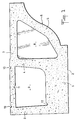
- FIG. 1 illustrates, in longitudinal section, a cornice element according to the invention.
- the cornice element according to the present invention is molded in one piece.
- the essential advantage of the cornice element according to the invention is that, having a classic appearance, it is however considerably reduced compared to the corresponding elements previously used.
- cornice element according to the invention also has the advantage, with certain possible modifications, of being able to give rise to derived cornice elements having these advantageous properties.
- notches made in the rear part of the upper wall 7. This rear part is that which forms the upper wall of the opening 9. These notches are shown at 10 and 11 in FIG. 1, they are arranged over the entire width of the element (therefore perpendicular to the section plane of said figure. 1) and are either on the upper face (notch 10) or on the lower face (notch 11) of said upper wall.
- a new cornice element is thus obtained which has been shown in longitudinal section in FIG. 2.
- This new cornice element is an integral part of the invention whatever its method of manufacture, that is to say that it is obtained from a cornice element previously described, by destruction of the rear part of the upper wall or by direct molding.
- This new cornice element has a substantial advantage in the construction field, namely that it makes it possible to use the opening 9 (which no longer has an upper wall) for making the chaining from the top of the wall on which the cornice will be willing.
- this new cornice element presents, with certain modifications, the possibility of easily making a third cornice element.
- the arrangement under consideration is a notch 12 formed in the lower part of the rear vertical wall 3. This notch 12, formed over the entire width of the element, makes it possible to destroy this wall by simple impact on the rear wall 3.
- a new cornice element is thus obtained which has been shown, in longitudinal section, in FIG. 3.
- This new cornice element is an integral part of the invention whatever its method of manufacture, that is to say that it is obtained from the new cornice element described in FIG. 1 by destruction, thanks to the notches , from the rear part of the upper wall, on the one hand, and from the rear vertical wall, on the other hand, or else by direct molding.
- the upper face of the sole 1 can be the object of various uses: for example, it can be used as a support surface to make a floor chaining or a ceiling chaining and it can serve as a receiving surface for the elements which will constitute the floor (or the ceiling).
Claims (5)
Applications Claiming Priority (2)
| Application Number | Priority Date | Filing Date | Title |
|---|---|---|---|
| FR8809886A FR2634507B1 (fr) | 1988-07-21 | 1988-07-21 | Elements de corniche en beton |
| FR8809886 | 1988-07-21 |
Publications (2)
| Publication Number | Publication Date |
|---|---|
| EP0354084A1 EP0354084A1 (de) | 1990-02-07 |
| EP0354084B1 true EP0354084B1 (de) | 1992-04-15 |
Family
ID=9368649
Family Applications (1)
| Application Number | Title | Priority Date | Filing Date |
|---|---|---|---|
| EP89402031A Expired - Lifetime EP0354084B1 (de) | 1988-07-21 | 1989-07-17 | Gesimselemente aus Beton |
Country Status (3)
| Country | Link |
|---|---|
| EP (1) | EP0354084B1 (de) |
| DE (1) | DE68901231D1 (de) |
| FR (1) | FR2634507B1 (de) |
Families Citing this family (3)
| Publication number | Priority date | Publication date | Assignee | Title |
|---|---|---|---|---|
| GB2316107B (en) * | 1995-05-11 | 1999-02-03 | Frederick Andrew Schofield | Building component |
| BR9608703A (pt) * | 1995-05-11 | 1999-12-07 | Frederick Andrew Schofield | Componente de edificação. |
| FR2772406B1 (fr) * | 1997-12-17 | 2000-02-18 | Materiaux Modernes De Construc | Bloc de chainage prefabrique avec sous-face |
Family Cites Families (3)
| Publication number | Priority date | Publication date | Assignee | Title |
|---|---|---|---|---|
| DE3042584C2 (de) * | 1980-11-12 | 1982-11-11 | Lorenz Ing.(grad.) 5168 Nideggen Cornelissen | Wandbildendes Mauerwerk im Hochbau und Kragstein hierfür |
| DE8402703U1 (de) * | 1984-01-31 | 1984-05-30 | BBZ Bauberatung-Ziegel und -Marketing GmbH, 8000 München | Hochlochziegel |
| FR2570412B1 (fr) * | 1984-09-18 | 1988-06-24 | Corneglio Georges | Element de construction, en particulier parpaing perfectionne, destine notamment a la realisation des murs de soubassement ou du chainage pour charpentes |
-
1988
- 1988-07-21 FR FR8809886A patent/FR2634507B1/fr not_active Expired - Lifetime
-
1989
- 1989-07-17 EP EP89402031A patent/EP0354084B1/de not_active Expired - Lifetime
- 1989-07-17 DE DE8989402031T patent/DE68901231D1/de not_active Expired - Fee Related
Non-Patent Citations (1)
| Title |
|---|
| M.MITTAG: "BAUKONSTRUKTIONSLEHRE" 15ème édition, 1971, pages 30,91,92,174,175, Institut für Bauplanung und Bautechnik, Detmold, D * |
Also Published As
| Publication number | Publication date |
|---|---|
| DE68901231D1 (de) | 1992-05-21 |
| FR2634507A1 (fr) | 1990-01-26 |
| FR2634507B1 (fr) | 1993-11-19 |
| EP0354084A1 (de) | 1990-02-07 |
Similar Documents
| Publication | Publication Date | Title |
|---|---|---|
| FR2486008A1 (fr) | Construction de toit de vehicule automobile | |
| EP0354084B1 (de) | Gesimselemente aus Beton | |
| EP0118411B1 (de) | Verankerungssysteme für Trennwände | |
| FR2474981A1 (fr) | Construction de pare-chocs pour un vehicule automobile | |
| FR2654764A1 (fr) | Element de corniche en pierre reconstituee notamment pour constructions. | |
| EP0438007B1 (de) | Schimmbad mit Stabilisierungsrippen | |
| EP3880540B1 (de) | Modulare a-säulenverstärkung | |
| FR2625757A1 (fr) | Element prefabrique pour la realisation de caniveaux d'ecoulement des eaux | |
| FR2996866A1 (fr) | Entrevous | |
| EP1010843B1 (de) | Stützfussvorrichtung für Stange oder Pfosten, insbesondere für Laube- oder Paneelunterstützung und Schliessverfahren dafür | |
| FR3102519A1 (fr) | Connecteur pour relier et fixer entre eux au moins deux corps | |
| BE1008863A3 (fr) | Dalle de beton et element de fermeture pour realiser la dalle. | |
| BE1010670A5 (fr) | Procede pour la fabrication d'une cave prefabriquee et la cave meme. | |
| FR2812323A1 (fr) | Piscine du type composee d'elements prefabriques en beton arme | |
| EP0926000B1 (de) | Kleintransportanhänger zum Transport von Pferden | |
| FR2474562A1 (fr) | Element de construction, pour la realisation de murets de retenue, de talus, de terrasses ou autres | |
| BE855714R (fr) | Systeme d'appui pour poutre prefabriquee en beton permettant de cacher la console du poteau | |
| FR2500865A1 (fr) | Jeu d'elements prefabriques pour la construction de murs de protection contre le bruit et pouvant etre garnis de plantes | |
| FR3104533A1 (fr) | Véhicule automobile à traction électrique avec bas de caisse renforcés | |
| FR2574103A1 (fr) | Piscine enterrable | |
| EP2071095A1 (de) | Balken, der einen Betonuntergurt umfasst und ein Fachwerk, das teilweise in diesen Betonuntergurt eingelassen ist | |
| FR2802956A1 (fr) | Element de construction, notamment element de rive pour le coffrage peripherique d'une dalle en beton | |
| FR2581102A1 (fr) | Mur prefabrique a contreforts internes | |
| BE701185A (de) | ||
| JP2003129557A (ja) | コンクリート側溝における閉蓋構造及びそれに用いるコンクリート蓋版 |
Legal Events
| Date | Code | Title | Description |
|---|---|---|---|
| PUAI | Public reference made under article 153(3) epc to a published international application that has entered the european phase |
Free format text: ORIGINAL CODE: 0009012 |
|
| AK | Designated contracting states |
Kind code of ref document: A1 Designated state(s): BE CH DE ES GB IT LI LU NL |
|
| 17P | Request for examination filed |
Effective date: 19900707 |
|
| 17Q | First examination report despatched |
Effective date: 19901123 |
|
| GRAA | (expected) grant |
Free format text: ORIGINAL CODE: 0009210 |
|
| AK | Designated contracting states |
Kind code of ref document: B1 Designated state(s): BE CH DE ES GB IT LI LU NL |
|
| PG25 | Lapsed in a contracting state [announced via postgrant information from national office to epo] |
Ref country code: IT Free format text: LAPSE BECAUSE OF FAILURE TO SUBMIT A TRANSLATION OF THE DESCRIPTION OR TO PAY THE FEE WITHIN THE PRE;WARNING: LAPSES OF ITALIAN PATENTS WITH EFFECTIVE DATE BEFORE 2007 MAY HAVE OCCURRED AT ANY TIME BEFORE 2007. THE CORRECT EFFECTIVE DATE MAY BE DIFFERENT FROM THE ONE RECORDED.SCRIBED TIME-LIMIT Effective date: 19920415 Ref country code: GB Effective date: 19920415 Ref country code: NL Effective date: 19920415 Ref country code: ES Free format text: THE PATENT HAS BEEN ANNULLED BY A DECISION OF A NATIONAL AUTHORITY Effective date: 19920415 |
|
| REF | Corresponds to: |
Ref document number: 68901231 Country of ref document: DE Date of ref document: 19920521 |
|
| NLV1 | Nl: lapsed or annulled due to failure to fulfill the requirements of art. 29p and 29m of the patents act | ||
| GBV | Gb: ep patent (uk) treated as always having been void in accordance with gb section 77(7)/1977 [no translation filed] | ||
| PLBE | No opposition filed within time limit |
Free format text: ORIGINAL CODE: 0009261 |
|
| STAA | Information on the status of an ep patent application or granted ep patent |
Free format text: STATUS: NO OPPOSITION FILED WITHIN TIME LIMIT |
|
| PG25 | Lapsed in a contracting state [announced via postgrant information from national office to epo] |
Ref country code: DE Effective date: 19930401 |
|
| 26N | No opposition filed | ||
| EPTA | Lu: last paid annual fee | ||
| PGFP | Annual fee paid to national office [announced via postgrant information from national office to epo] |
Ref country code: CH Payment date: 19950717 Year of fee payment: 7 |
|
| PGFP | Annual fee paid to national office [announced via postgrant information from national office to epo] |
Ref country code: LU Payment date: 19950801 Year of fee payment: 7 |
|
| PG25 | Lapsed in a contracting state [announced via postgrant information from national office to epo] |
Ref country code: LU Free format text: LAPSE BECAUSE OF NON-PAYMENT OF DUE FEES Effective date: 19960717 |
|
| PG25 | Lapsed in a contracting state [announced via postgrant information from national office to epo] |
Ref country code: LI Effective date: 19960731 Ref country code: CH Effective date: 19960731 |
|
| REG | Reference to a national code |
Ref country code: CH Ref legal event code: PL |
|
| PGFP | Annual fee paid to national office [announced via postgrant information from national office to epo] |
Ref country code: BE Payment date: 20080814 Year of fee payment: 20 |