EP0352623A2 - Appareil à poser des rivets aveugles - Google Patents
Appareil à poser des rivets aveugles Download PDFInfo
- Publication number
- EP0352623A2 EP0352623A2 EP89113265A EP89113265A EP0352623A2 EP 0352623 A2 EP0352623 A2 EP 0352623A2 EP 89113265 A EP89113265 A EP 89113265A EP 89113265 A EP89113265 A EP 89113265A EP 0352623 A2 EP0352623 A2 EP 0352623A2
- Authority
- EP
- European Patent Office
- Prior art keywords
- blind
- rivet
- slide
- tool according
- blind riveting
- Prior art date
- Legal status (The legal status is an assumption and is not a legal conclusion. Google has not performed a legal analysis and makes no representation as to the accuracy of the status listed.)
- Withdrawn
Links
Images

Classifications
-
- B—PERFORMING OPERATIONS; TRANSPORTING
- B21—MECHANICAL METAL-WORKING WITHOUT ESSENTIALLY REMOVING MATERIAL; PUNCHING METAL
- B21J—FORGING; HAMMERING; PRESSING METAL; RIVETING; FORGE FURNACES
- B21J15/00—Riveting
- B21J15/10—Riveting machines
- B21J15/30—Particular elements, e.g. supports; Suspension equipment specially adapted for portable riveters
- B21J15/32—Devices for inserting or holding rivets in position with or without feeding arrangements
-
- B—PERFORMING OPERATIONS; TRANSPORTING
- B21—MECHANICAL METAL-WORKING WITHOUT ESSENTIALLY REMOVING MATERIAL; PUNCHING METAL
- B21J—FORGING; HAMMERING; PRESSING METAL; RIVETING; FORGE FURNACES
- B21J15/00—Riveting
- B21J15/02—Riveting procedures
- B21J15/04—Riveting hollow rivets mechanically
- B21J15/043—Riveting hollow rivets mechanically by pulling a mandrel
-
- B—PERFORMING OPERATIONS; TRANSPORTING
- B21—MECHANICAL METAL-WORKING WITHOUT ESSENTIALLY REMOVING MATERIAL; PUNCHING METAL
- B21J—FORGING; HAMMERING; PRESSING METAL; RIVETING; FORGE FURNACES
- B21J15/00—Riveting
- B21J15/10—Riveting machines
- B21J15/105—Portable riveters
Definitions
- the invention relates to a blind riveting device according to the preamble of patent claim 1.
- blind riveting device DE-AS 24 41 707
- the blind rivets are individually shot from a delivery line opening at an acute angle into the locking tube of the device into a loading chamber between the chuck and the mouthpiece of the device and held there by a leaf spring until the rivet mandrel is removed the opening jaws of the chuck is detected. This is difficult due to the poor alignment of the blind rivet.
- the loading chamber and the stroke length of the rivet head are long.
- the object of the invention is to provide the blind riveting device of the type mentioned at the outset with a simply constructed and reliably working feed device.
- the blind rivet inserted into the transfer element is held in the transfer element in a certain position, so that the blind rivet is aligned with the chuck when the blind rivet is transported to the loading position.
- the blind rivet can then be gripped by the chuck.
- the transfer element is then removed and returns to the loading position for receiving a new blind rivet, the blind rivet emerging from the lateral outlet opening of the transfer element.
- the transfer element thus has a holding device for inserting and holding the blind rivet in a specific position and the outlet opening connected to the holding device.
- the holding device in the transfer element is a recess into which the blind rivet is shot and in which it is held by clamping or frictional force.
- Pneumatic or electromagnetic elements can also be used for the holding device.
- an alignment device is also provided in the loading position, by means of which the blind rivet is additionally aligned in the aligned position with the chuck becomes. This applies in particular to non-round rivets, for which safe insertion is also made possible.
- the transfer element is designed as a reciprocating slide which can be displaced approximately transversely and in particular obliquely at an obtuse angle to the direction of movement of the rivet head.
- the transfer element can also be designed as a revolver or swivel element, which grips the blind rivet in the manner explained above, holds it, transports it in front of the chuck into the loading position, the blind rivet being aligned with the chuck, whereupon the one gripped by the chuck Blind rivet is removable from the transition element.
- the slide By means of the slide, precise alignment of the blind rivet can be achieved according to the invention with simple means by pushing the blind rivet out of the preferably pneumatically operated delivery line into the recess of the slide.
- the slider is slotted, so the recess consists of two jaws, which expand slightly when the blind rivet enters, so that the blind rivet is held firmly in the recess and is now moved upwards in this orientation in front of the chuck.
- the drive cylinder for the rivet head is actuated and the single-jaw chuck moves over the rivet mandrel and takes over the blind rivet from the slide by pulling the slide away from this loading position and thereby the blind rivet emerging from the recess through the slot.
- the rivet head is then moved further, riveting is carried out and the mandrel is torn off.
- the slide comes into position in front of the inlet channel and takes over the next blind there rivet, which is conveyed by a blast of compressed air from a magazine with separating device.
- the drive device for the slide is particularly advantageous because the slide movement is inevitably coupled to the rivet head drive.
- swivel arms with sliding surfaces are attached to the slide.
- the drive of the rivet head and slide can also be synchronized with a pneumatic or electrical control.
- the sliding surfaces interact with parts of the chuck or the rivet head, so that when the rivet head is moved, the swivel arms are inevitably and positively pivoted and the slider is thus actuated.
- the force for the counter movement of the slide is provided by a spring, the sliding surfaces interacting with the rivet head taking over the guidance of the slide and also a stop surface ensuring that the upper end position of the slide is exactly maintained.
- the slide is held in its lower end position by a lock, which is unlocked by the rivet head on its way to the rear position and thus releases the slide for its upward stroke.
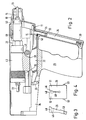
- a chuck 10 serves to receive the mandrel 11 of a blind rivet 12, the hollow rivet of which is inserted up to a flange 15 in a bore of workpieces not to be connected, a mouthpiece 16 of the housing 18 of the blind rivet device being able to be placed on the workpieces.
- the chuck 10 is part of a rivet head 20, which is provided with a pulling device 42, upon actuation of which a tensile force is exerted on the mandrel 11 held in the chuck 10, so that the hollow rivet 14 is crowned, causing riveting, whereupon the mandrel when the pulling device is actuated further, it is torn off and vacuumed through a central channel and exits at 22.
- a drive cylinder not shown, for displacing the rivet head from the loading position shown in FIG. 1, into the working or riveting position, which is almost reached in FIG. 2, in which the hollow rivet part 14 is just through an opening 23 in the mouthpiece 16 passes through.
- the feed device for the blind rivets consists of a slide 25, on which an extension 26 is provided, which is guided in a channel 27.
- the slider 25 is guided at an obtuse angle to the axis of the rivet head 20 in one direction of movement.
- the channel 27 is formed in a housing 28 which forms part of the handle 29 of the blind riveting device.
- the slider 25 is pressed upwards by a spring 30 into the position shown in FIG. 1, which is fixed by a stop 31.
- a compressed air drive is also possible instead of the spring.
- the swivel arm 32 is articulated by means of a rotatable tab 35 on the housing 36 of the blind riveting device.
- the swivel arm 32 has a first sliding surface 38 and a second sliding surface 39, both of which face the rivet head 20.
- the first sliding surface 38 cooperates with a shoulder 43 provided on the rivet head 20, during further return both sliding surfaces 38 and 39 interact with a roller 41 which is mounted on the cylinder 42 of the pulling device.
- the slide 25 has a recess 46 in the form of a bore which serves to receive the blind rivet 12. Above the bore 46, the slide 25 is provided with a slot 48, the width of which is selected so that the blind rivet can emerge from the bore 46 when the slide is actuated. In order to facilitate or enable this emergence, a further longer slot 49 is provided below the bore 46, which divides the slide into two tongues 50 and 51, which are pressed apart due to the slot 49 and the elastic or resilient properties of their material, when the hollow rivet part 14 passes from the recess 46 into the slot 48 and is thus removed from the slide. The blind rivet is thus enclosed and held by the two tongues 50 and 51 or the sections of the recess 46 lying on both sides of the slot 48 or 49.
- the bearing points for the two swivel arms 32 are designated 53 in FIG. 4.
- a bore is also provided in the housing parallel to the axis of the rivet head 20 as a feed line 55 for the blind rivet.
- the blind rivets are contained in a magazine (not shown), get from the magazine into a vibrating pot of known design, in which they are separated, whereupon they are brought into the channel 55 by a compressed air pulse via a line (not shown) and thereby at an opening pawl 58 are inserted into the recess 46 of the slide 25, which is brought into the position shown in FIG. 2.
- the pawl 58 bears against the flange 15 of the blind rivet so that it does not fall out.
- the rivet head After completion of the riveting process, the rivet head returns from the working position to the loading position shown in FIG. 1. Shortly before reaching the loading position, the slide 25 is unlocked by a retracting rod and pushed up under the force of the spring 30 until the rivet head 20 has been pushed back so far that the roller 41 is released and the stop 31 is reached. 1 and the slide 25 is axially aligned with the chuck 10 in its upper end position. An additional security against tilting of the mandrel 11 when it is received in the chuck is provided by a fork 60, in the slot 61 of which the Pull mandrel 11 occurs.
- the rivet head 20 is now moved forward from the loading position shown in FIG. 1 by actuating the drive cylinder, so that the mandrel 11 enters the clamping device 10.
- the roller 41 moves further forward and then reaches the sliding surfaces 39 and 38.
- the pulling mandrel 11 has already been taken over by the chuck 10.
- the further movement of the rivet head 20 to the front can now pivot the swivel arm 32 in a clockwise direction, so that the slider 25 is pushed down and the hollow rivet 14 is pushed out of the slot 48 via the spreading slot Recess 46 emerges.
- the fork 60 is pivotally mounted and is pivoted away from the chuck 10 upwards.
- the slide 25 has now been pushed so far down from the sliding surface 38 that the path for the rivet head 20 is free.
- the roller 41 slides on the sliding surface 39 and when the rivet head 20 is advanced further, the slide 25 is thus brought into the lower end position shown in FIG. 2, in which the recess 46 is arranged in front of the inlet channel 45.
- This end position is defined by the stop surface 38 on the cylinder housing 42, as shown in FIG. 2.
- the rivet head 20 continues to advance until the blind rivet emerges from the opening 23 of the mouthpiece 16.
- the slide 25 is locked in its lower end position by a lock.
- the next blind rivet is now inserted into the slide 25 by a blast of compressed air.
- the setting and riveting process can take place at the same time.
Landscapes
- Engineering & Computer Science (AREA)
- Mechanical Engineering (AREA)
- Insertion Pins And Rivets (AREA)
- Automatic Assembly (AREA)
Applications Claiming Priority (2)
| Application Number | Priority Date | Filing Date | Title |
|---|---|---|---|
| DE3825675 | 1988-07-28 | ||
| DE3825675A DE3825675A1 (de) | 1988-07-28 | 1988-07-28 | Blindnietgeraet |
Publications (2)
| Publication Number | Publication Date |
|---|---|
| EP0352623A2 true EP0352623A2 (fr) | 1990-01-31 |
| EP0352623A3 EP0352623A3 (fr) | 1990-12-05 |
Family
ID=6359771
Family Applications (1)
| Application Number | Title | Priority Date | Filing Date |
|---|---|---|---|
| EP19890113265 Withdrawn EP0352623A3 (fr) | 1988-07-28 | 1989-07-19 | Appareil à poser des rivets aveugles |
Country Status (2)
| Country | Link |
|---|---|
| EP (1) | EP0352623A3 (fr) |
| DE (1) | DE3825675A1 (fr) |
Cited By (2)
| Publication number | Priority date | Publication date | Assignee | Title |
|---|---|---|---|---|
| EP0456852A1 (fr) * | 1990-05-15 | 1991-11-21 | VVG Befestigungstechnik Beteiligungs-GmbH | Outil de rivetage avec alimentation de rivets automatique |
| EP0737528A1 (fr) * | 1995-04-12 | 1996-10-16 | Emhart Inc. | Outil d'alimentation d'éléments de fixation |
Families Citing this family (2)
| Publication number | Priority date | Publication date | Assignee | Title |
|---|---|---|---|---|
| DE20013365U1 (de) | 2000-08-03 | 2000-11-30 | Avdel Verbindungselemente | Vorrichtung zum Laden eines Nietmoduls mit Dornbruchblindnieten |
| DE20013585U1 (de) | 2000-08-04 | 2000-12-07 | Avdel Verbindungselemente | Vorrichtung zum Laden eines Nietmoduls mit Blindnietmuttern |
Citations (3)
| Publication number | Priority date | Publication date | Assignee | Title |
|---|---|---|---|---|
| GB524687A (en) * | 1939-02-06 | 1940-08-13 | Aherne Heron John | Improvements relating to riveting guns and like apparatus |
| US4604889A (en) * | 1984-12-27 | 1986-08-12 | Huck Manufacturing Company | Automated installation tool for blind fasteners |
| EP0285739A1 (fr) * | 1987-04-10 | 1988-10-12 | Roald Di Von Maerzthal Roald | Appareil d'alimentation, de renversement et de chargement frontal automatique de rivets, muni d'un pistolet de rivetage |
Family Cites Families (3)
| Publication number | Priority date | Publication date | Assignee | Title |
|---|---|---|---|---|
| AR230737A1 (es) * | 1981-06-29 | 1984-06-29 | Gen Electro Mech Corp | Dispositivo para alinear remaches o elementos similares |
| GB2159751B (en) * | 1984-06-05 | 1987-12-31 | Tucker Fasteners Ltd | A blind-riveting machine |
| GB2180482B (en) * | 1985-09-19 | 1989-01-25 | Avdel Ltd | Apparatus for installing fasteners |
-
1988
- 1988-07-28 DE DE3825675A patent/DE3825675A1/de not_active Withdrawn
-
1989
- 1989-07-19 EP EP19890113265 patent/EP0352623A3/fr not_active Withdrawn
Patent Citations (3)
| Publication number | Priority date | Publication date | Assignee | Title |
|---|---|---|---|---|
| GB524687A (en) * | 1939-02-06 | 1940-08-13 | Aherne Heron John | Improvements relating to riveting guns and like apparatus |
| US4604889A (en) * | 1984-12-27 | 1986-08-12 | Huck Manufacturing Company | Automated installation tool for blind fasteners |
| EP0285739A1 (fr) * | 1987-04-10 | 1988-10-12 | Roald Di Von Maerzthal Roald | Appareil d'alimentation, de renversement et de chargement frontal automatique de rivets, muni d'un pistolet de rivetage |
Cited By (3)
| Publication number | Priority date | Publication date | Assignee | Title |
|---|---|---|---|---|
| EP0456852A1 (fr) * | 1990-05-15 | 1991-11-21 | VVG Befestigungstechnik Beteiligungs-GmbH | Outil de rivetage avec alimentation de rivets automatique |
| EP0737528A1 (fr) * | 1995-04-12 | 1996-10-16 | Emhart Inc. | Outil d'alimentation d'éléments de fixation |
| US5640758A (en) * | 1995-04-12 | 1997-06-24 | Emhart Inc. | Component feeder with reciprocal and rotatable magazine |
Also Published As
| Publication number | Publication date |
|---|---|
| EP0352623A3 (fr) | 1990-12-05 |
| DE3825675A1 (de) | 1990-02-01 |
Similar Documents
| Publication | Publication Date | Title |
|---|---|---|
| DE3631657C2 (de) | Vorrichtung zum Setzen von Befestigungselementen mit einer Beschickungseinrichtung | |
| DE2516733C2 (de) | Nietvorrichtung zum Setzen von Blindnieten mit rohrförmiger Muffe | |
| DE2903351C2 (fr) | ||
| EP1841559A1 (fr) | Changeur de capsules de soudage par point | |
| DE3641727C2 (de) | Vakuumvorrichtung, insbesondere für die Handhabung von Siliziumplättchen | |
| DE1943190C3 (de) | Blindnietvorrichtung zum Setzen von Hohlnieten | |
| DE1627730A1 (de) | Vorrichtung fuer den Zusammenbau von Muttern und Unterlegscheiben od.dgl. mit Schraubenbolzen od.dgl. | |
| EP2476518B1 (fr) | Unité d'insertion d'un élément de fixation | |
| DE2754176A1 (de) | Vorrichtung zum beladen von werkzeugmaschinen, insbesondere drehmaschinen | |
| EP0456852B1 (fr) | Outil de rivetage avec alimentation de rivets automatique | |
| EP0352623A2 (fr) | Appareil à poser des rivets aveugles | |
| DE2441707C3 (de) | Automatische Nietanlage | |
| DE1935451C2 (de) | Vorrichtung zum Vereinzeln und Einführen von bolzenförmigen Rohlingen an einer Bearbeitungsmaschine | |
| DE3508397A1 (de) | Maschine zum aufquetschbestuecken von kabeladerenden mit aderendhuelsen o.dgl. anschlusselementen | |
| WO1985004290A1 (fr) | Machine pour munir par sertissage les extremites des conducteurs d'un cable, de douilles d'expremite ou d'autres elements de connexion | |
| DE2931639A1 (de) | Vorrichtung zum anbringen eines begrenzungsteils an einem reissverschlussband | |
| DE3508354A1 (de) | Maschine zum aufquetschbestuecken von kabeladerenden mit aderendhuelsen od.dgl. anschlusselementen | |
| CH644504A5 (de) | Vorrichtung zur anbringung von schiebern an reissverschlussstreifen. | |
| DE2154894C3 (de) | Verschließvorrichtung fur Beutel | |
| DE1924237C3 (de) | Vorrichtung zum Ausscheiden von Kapselteilen | |
| DD160759A5 (de) | Verschliesseinrichtung | |
| EP0308822B1 (fr) | Machine-outil | |
| DE2225439A1 (de) | Bhndnietvorrichtung zum Setzen von rohrförmigen Blmdnieten | |
| WO1985004288A1 (fr) | Machine pour equiper par serrage des extremites de conducteur de cable de manchons terminaux de conducteurs ou d'autres elements de raccord | |
| DE2453525C2 (de) | Einrichtung zur Bildung von Fadenklammerrohlingen und zu deren lagegerechter Zusammenführung mit kontinuierlich geförderten Falzbogen |
Legal Events
| Date | Code | Title | Description |
|---|---|---|---|
| PUAI | Public reference made under article 153(3) epc to a published international application that has entered the european phase |
Free format text: ORIGINAL CODE: 0009012 |
|
| AK | Designated contracting states |
Kind code of ref document: A2 Designated state(s): AT BE CH DE ES FR GB IT LI NL |
|
| PUAL | Search report despatched |
Free format text: ORIGINAL CODE: 0009013 |
|
| AK | Designated contracting states |
Kind code of ref document: A3 Designated state(s): AT BE CH DE ES FR GB IT LI NL |
|
| 17P | Request for examination filed |
Effective date: 19910102 |
|
| 17Q | First examination report despatched |
Effective date: 19920430 |
|
| STAA | Information on the status of an ep patent application or granted ep patent |
Free format text: STATUS: THE APPLICATION IS DEEMED TO BE WITHDRAWN |
|
| 18D | Application deemed to be withdrawn |
Effective date: 19921111 |