EP0737528A1 - Outil d'alimentation d'éléments de fixation - Google Patents
Outil d'alimentation d'éléments de fixation Download PDFInfo
- Publication number
- EP0737528A1 EP0737528A1 EP96302297A EP96302297A EP0737528A1 EP 0737528 A1 EP0737528 A1 EP 0737528A1 EP 96302297 A EP96302297 A EP 96302297A EP 96302297 A EP96302297 A EP 96302297A EP 0737528 A1 EP0737528 A1 EP 0737528A1
- Authority
- EP
- European Patent Office
- Prior art keywords
- tool
- magazine
- fastener
- feeder
- component
- Prior art date
- Legal status (The legal status is an assumption and is not a legal conclusion. Google has not performed a legal analysis and makes no representation as to the accuracy of the status listed.)
- Granted
Links
Images


Classifications
-
- B—PERFORMING OPERATIONS; TRANSPORTING
- B21—MECHANICAL METAL-WORKING WITHOUT ESSENTIALLY REMOVING MATERIAL; PUNCHING METAL
- B21J—FORGING; HAMMERING; PRESSING METAL; RIVETING; FORGE FURNACES
- B21J15/00—Riveting
- B21J15/10—Riveting machines
- B21J15/30—Particular elements, e.g. supports; Suspension equipment specially adapted for portable riveters
- B21J15/32—Devices for inserting or holding rivets in position with or without feeding arrangements
-
- Y—GENERAL TAGGING OF NEW TECHNOLOGICAL DEVELOPMENTS; GENERAL TAGGING OF CROSS-SECTIONAL TECHNOLOGIES SPANNING OVER SEVERAL SECTIONS OF THE IPC; TECHNICAL SUBJECTS COVERED BY FORMER USPC CROSS-REFERENCE ART COLLECTIONS [XRACs] AND DIGESTS
- Y10—TECHNICAL SUBJECTS COVERED BY FORMER USPC
- Y10T—TECHNICAL SUBJECTS COVERED BY FORMER US CLASSIFICATION
- Y10T29/00—Metal working
- Y10T29/53—Means to assemble or disassemble
- Y10T29/53478—Means to assemble or disassemble with magazine supply
- Y10T29/53487—Assembling means comprising hand-manipulatable implement
- Y10T29/53496—Assembling means comprising hand-manipulatable implement comprising driver for snap-off-mandrel fastener; e.g., Pop [TM] riveter
-
- Y—GENERAL TAGGING OF NEW TECHNOLOGICAL DEVELOPMENTS; GENERAL TAGGING OF CROSS-SECTIONAL TECHNOLOGIES SPANNING OVER SEVERAL SECTIONS OF THE IPC; TECHNICAL SUBJECTS COVERED BY FORMER USPC CROSS-REFERENCE ART COLLECTIONS [XRACs] AND DIGESTS
- Y10—TECHNICAL SUBJECTS COVERED BY FORMER USPC
- Y10T—TECHNICAL SUBJECTS COVERED BY FORMER US CLASSIFICATION
- Y10T29/00—Metal working
- Y10T29/53—Means to assemble or disassemble
- Y10T29/53709—Overedge assembling means
- Y10T29/53717—Annular work
- Y10T29/53726—Annular work with second workpiece inside annular work one workpiece moved to shape the other
- Y10T29/5373—Annular work with second workpiece inside annular work one workpiece moved to shape the other comprising driver for snap-off-mandrel fastener; e.g., Pop [TM] riveter
Definitions
- This invention relates to a component installation tool of the type having a rearward stroke to accommodate delivery of a component to the front of the tool and a forward stroke to engage, deliver and install the component at a workpiece, which tool comprises a housing, a reciprocating mechanism contained therein, and a feeder support mounted on the housing,
- fasteners such as blind-riveting assemblies and weld studs, or other fasteners which have cylindrical shanks with radially projecting flanges
- means e.g. of a nosepiece, which closely embraces the shank. It is often also desirable that such means surrounds the shank completely, or as completely as possible, especially if the means, as is the case with a nosepiece in blind riveting, is going to apply pressure to the flange of the fastener.
- the present invention provides a component installation tool of the type having a rearward stroke to accommodate delivery of a component to the front of the tool and a forward stroke to engage, deliver and install the component at a workpiece, which tool comprises a housing, a reciprocating mechanism contained therein, and a feeder support mounted on the housing, characterised in that the tool comprises
- the present invention further provides a feeder for providing a supply of fasteners to a reciprocating fastener installation tool which engages a fastener, delivers the fastener to a workpiece and installs the fastener thereon, characterised in that the feeder comprises;
- the chambers are disposed around the magazine at an angular separation corresponding to the angular rotation of the magazine produced by the tool movement.
- the reciprocating means preferably comprises a pivot arm rotatably mounted on the feeder support and supporting the axis of the magazine.
- the chamber is preferably shaped to receive the fastener from the tube in the orientation required for the fastener to be engaged by the installation tool.
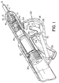
- Figure 1 illustrates a rivet presentation and setting apparatus of a type particularly designed for setting a double headed rivet which includes a rivet body 2, a head or flange 4 and a mandrel 6.
- the mandrel includes a first, setting head at the opposite end of the rivet body from the flange 4 for expanding the rivet body when the mandrel is pulled and a pulling head 10.
- the presentation and setting apparatus is described in particular detail in co-pending application Serial No. S4830.
- This apparatus includes a housing 12 which is connected to a tool body, not shown, which includes a suitable reciprocating hydraulic piston and appropriate controls therefor.
- a plurality of supporting segments 14 are provided for restraining the rivet flange 4 when the mandrel head 10 is pulled by pulling segments 16 which engage the reverse surface of the mandrel head 10 at the front end of a collet assembly 18.
- the collet assembly is suitably coupled at its rear end to the hydraulic piston, for example by threads 20.
- Means are also provided in the tool for removing the broken off mandrel through a hollow tube which runs through the centre of the collet assembly as is well known in this art.
- the presentation and setting apparatus is in its forward-most position with a rivet gripped in the pulling jaws and ready to be presented to and set in a workpiece, also not shown.
- FIG. 1 also illustrates a feeder 22 in particular accord with the present invention.
- the feeder is positioned within an extension 24 of housing 12 which also contains the delivery end 26 of a supply tube through which rivets are delivered from a remote source.
- the feeder 22 comprises a rotary magazine 28 which is mounted for rotation on an axis 30 at the end of a pivot arm 32 which is mounted at a rearward location in the housing extension 24.
- the magazine 28 comprises a plurality of chambers 34, three being illustrated in the preferred embodiment although two or more may be used if desired.
- Each chamber comprises an open-topped socket 36 for receiving the rivet body 2 and mandrel head 8 and a semicircular seat 38 for receiving flange 4.
- a significant increase in the efficiency and speed of operation of the tool is achieved by virtue of the fact that the chamber 34 is positioned in alignment with the end of the delivery tube 26 during the time that the presentation and setting apparatus presents and sets the rivet 2 in a workpiece.
- the chamber 34 is positioned in alignment with the end of the delivery tube 26 during the time that the presentation and setting apparatus presents and sets the rivet 2 in a workpiece.
- Figure 2 shows the mechanism of Figure 1 except that the collet assembly and support segments have been retracted fully into the tool, clearing the interior of the housing 12.
- the pivot arm 32 has been operated to move the magazine 28 through a slot 40 in the side of housing 12 which carries a new rivet 2' into a loading position immediately in front of the support segments 14.
- the collet assembly and support segments are now driven forward and the support segments pass over the mandrel head 10' until they engage the rivet flange 4'.
- the collet assembly 18 moves forward relative to the support segments until the pulling segments 16 open, receive and engage the head 10'.
- the coupling member 20 engages the rear end of the support segments 14 which in turn apply pressure through the rivet flange 4' on the seat 38 of chamber 34.
- the magazine now begins to rotate on its axis and pivot arm 32 begins to pivot, lowering the magazine out of the path of the support jaws. Since the rivet is held by its head 10' and mandrel 6', the rivet will remain aligned with the support segments and pulling segments as the magazine 28 pivots and rotates out from under it.
- Figure 3 shows a further stage of this operation.
- the magazine has been pivoted nearly out of the housing 12 and the rivet is being carried forward through the housing 12 by the support and pulling segments.
- Continued motion returns the apparatus to the position illustrated in Figure 1 where the rivet is ready for presentation and setting in a workpiece.
- the magazine has been rotated to present another chamber 34 for receipt of the next rivet from the supply tube.
- control of the pivot arm 32 may be exerted automatically by means of a spring so that it moves into the housing 12 as soon as the support segments 14 move out of the way or a positive hydraulic control may be incorporated into the tool operating mechanism.
- the rotary magazine may have its axis mounted in a slot oriented perpendicularly to the axis of movement of the collet assembly so that, as the magazine rotates in delivering a rivet, the axial moves vertically down the slot, carrying the magazine out of the housing.
- a spring or control device returns the magazine into the housing carrying the next rivet in the next chamber.
Landscapes
- Engineering & Computer Science (AREA)
- Mechanical Engineering (AREA)
- Portable Nailing Machines And Staplers (AREA)
- Automatic Assembly (AREA)
Applications Claiming Priority (2)
| Application Number | Priority Date | Filing Date | Title |
|---|---|---|---|
| US421589 | 1989-10-16 | ||
| US08/421,589 US5640758A (en) | 1995-04-12 | 1995-04-12 | Component feeder with reciprocal and rotatable magazine |
Publications (2)
| Publication Number | Publication Date |
|---|---|
| EP0737528A1 true EP0737528A1 (fr) | 1996-10-16 |
| EP0737528B1 EP0737528B1 (fr) | 2001-05-23 |
Family
ID=23671195
Family Applications (1)
| Application Number | Title | Priority Date | Filing Date |
|---|---|---|---|
| EP96302297A Expired - Lifetime EP0737528B1 (fr) | 1995-04-12 | 1996-04-01 | Outil d'alimentation d'éléments de fixation |
Country Status (4)
| Country | Link |
|---|---|
| US (1) | US5640758A (fr) |
| EP (1) | EP0737528B1 (fr) |
| JP (1) | JPH08309675A (fr) |
| DE (1) | DE69612904T2 (fr) |
Cited By (1)
| Publication number | Priority date | Publication date | Assignee | Title |
|---|---|---|---|---|
| EP1077096A2 (fr) * | 1999-08-18 | 2001-02-21 | Emhart Inc. | Dispositif de pose des éléments de fixation à deux pièces |
Families Citing this family (6)
| Publication number | Priority date | Publication date | Assignee | Title |
|---|---|---|---|---|
| DE19812085A1 (de) * | 1998-03-19 | 1999-09-23 | Ejot Verbindungstech Gmbh & Co | Montiervorrichtung für Bauteile |
| DE20013585U1 (de) * | 2000-08-04 | 2000-12-07 | Avdel Verbindungselemente GmbH, 30851 Langenhagen | Vorrichtung zum Laden eines Nietmoduls mit Blindnietmuttern |
| US20040231123A1 (en) * | 2003-05-22 | 2004-11-25 | Woyciesjes James N. | Remote fastener presenter |
| DE102005041534A1 (de) | 2005-08-31 | 2007-03-01 | Newfrey Llc, Newark | Verfahren und Vorrichtung zum Zuführen von Verbindungselementen zu einem Verarbeitungsgerät |
| US8449234B2 (en) * | 2007-01-16 | 2013-05-28 | Harry E. Taylor | Blind rivet |
| JP6163388B2 (ja) * | 2013-08-29 | 2017-07-12 | 株式会社Subaru | 溶接システム |
Citations (3)
| Publication number | Priority date | Publication date | Assignee | Title |
|---|---|---|---|---|
| US4604889A (en) * | 1984-12-27 | 1986-08-12 | Huck Manufacturing Company | Automated installation tool for blind fasteners |
| US4662206A (en) * | 1984-12-03 | 1987-05-05 | Usm Corporation | Rivet/stud feeder |
| EP0352623A2 (fr) * | 1988-07-28 | 1990-01-31 | Böllhoff & Co, GmbH & Co KG | Appareil à poser des rivets aveugles |
Family Cites Families (4)
| Publication number | Priority date | Publication date | Assignee | Title |
|---|---|---|---|---|
| US3561641A (en) * | 1968-12-19 | 1971-02-09 | Eltec Inc | Fastener supply device |
| US3750257A (en) * | 1971-12-30 | 1973-08-07 | Kaynar Mfg Co | Systematized apparatus for driving fasteners |
| US3971421A (en) * | 1974-02-26 | 1976-07-27 | Triad Fastener Corporation | Air-powered, self-feeding screw driving tool |
| US5098003A (en) * | 1990-06-28 | 1992-03-24 | Design Tool, Inc. | Fastener driving apparatus and method |
-
1995
- 1995-04-12 US US08/421,589 patent/US5640758A/en not_active Expired - Fee Related
-
1996
- 1996-04-01 DE DE69612904T patent/DE69612904T2/de not_active Expired - Fee Related
- 1996-04-01 EP EP96302297A patent/EP0737528B1/fr not_active Expired - Lifetime
- 1996-04-09 JP JP8086733A patent/JPH08309675A/ja active Pending
Patent Citations (3)
| Publication number | Priority date | Publication date | Assignee | Title |
|---|---|---|---|---|
| US4662206A (en) * | 1984-12-03 | 1987-05-05 | Usm Corporation | Rivet/stud feeder |
| US4604889A (en) * | 1984-12-27 | 1986-08-12 | Huck Manufacturing Company | Automated installation tool for blind fasteners |
| EP0352623A2 (fr) * | 1988-07-28 | 1990-01-31 | Böllhoff & Co, GmbH & Co KG | Appareil à poser des rivets aveugles |
Cited By (2)
| Publication number | Priority date | Publication date | Assignee | Title |
|---|---|---|---|---|
| EP1077096A2 (fr) * | 1999-08-18 | 2001-02-21 | Emhart Inc. | Dispositif de pose des éléments de fixation à deux pièces |
| EP1077096A3 (fr) * | 1999-08-18 | 2001-12-12 | Emhart Inc. | Dispositif de pose des éléments de fixation à deux pièces |
Also Published As
| Publication number | Publication date |
|---|---|
| JPH08309675A (ja) | 1996-11-26 |
| DE69612904D1 (de) | 2001-06-28 |
| EP0737528B1 (fr) | 2001-05-23 |
| US5640758A (en) | 1997-06-24 |
| DE69612904T2 (de) | 2001-11-15 |
Similar Documents
| Publication | Publication Date | Title |
|---|---|---|
| US4765175A (en) | Apparatus for installing fasteners | |
| EP0284257B1 (fr) | Dispositif pour amener les rivets | |
| US6347449B1 (en) | Modular portable rivet setting tool | |
| AU661532B2 (en) | Blind rivet setting tool | |
| EP0491193B1 (fr) | Appareil automatique d'alimentation des rivets | |
| EP0995518B1 (fr) | Contrôle du cycle de travail d'une riveteuse | |
| US5897045A (en) | Fastener dispensing apparatus for stand-up fastener driving tool and method therefor | |
| EP2394791A1 (fr) | Embout divisé destiné à entraîner des vis assemblées | |
| US9586257B2 (en) | Combination collar feeder and swaging tool | |
| EP0399798B1 (fr) | Appareil à poser des éléments de fixation | |
| US3763541A (en) | Method of and apparatus for setting blind fasteners | |
| EP0737528B1 (fr) | Outil d'alimentation d'éléments de fixation | |
| US6079604A (en) | Rivet tool escapement mechanism | |
| EP0995519B1 (fr) | Dispositif ajustable pour l'alimentation de rivets à un outil de rivetage | |
| JP4197811B2 (ja) | リベット締結工具 | |
| US5400942A (en) | Automatic fastener feed apparatus and method | |
| JPH04251627A (ja) | ブラインドリベット装着工具用ノーズピース装置 | |
| EP0185475B1 (fr) | Dispositif pour charger un outil d'un rivet | |
| EP1479462A1 (fr) | Dispositif de présentation d'éléments de fixation à distance | |
| EP0173817A1 (fr) | Dispositif pour poser un élément de fixation aveugle | |
| JPH06218637A (ja) | ねじ締め装置 | |
| US5519927A (en) | Rivet setting tool | |
| US20050091814A1 (en) | Nut insert installation system and method of use | |
| EP0813461B1 (fr) | Dispositif d'introduction d'inserts dans une piece de tole |
Legal Events
| Date | Code | Title | Description |
|---|---|---|---|
| PUAI | Public reference made under article 153(3) epc to a published international application that has entered the european phase |
Free format text: ORIGINAL CODE: 0009012 |
|
| AK | Designated contracting states |
Kind code of ref document: A1 Designated state(s): DE FR GB |
|
| 17P | Request for examination filed |
Effective date: 19970402 |
|
| 17Q | First examination report despatched |
Effective date: 19990308 |
|
| GRAG | Despatch of communication of intention to grant |
Free format text: ORIGINAL CODE: EPIDOS AGRA |
|
| GRAG | Despatch of communication of intention to grant |
Free format text: ORIGINAL CODE: EPIDOS AGRA |
|
| GRAH | Despatch of communication of intention to grant a patent |
Free format text: ORIGINAL CODE: EPIDOS IGRA |
|
| GRAH | Despatch of communication of intention to grant a patent |
Free format text: ORIGINAL CODE: EPIDOS IGRA |
|
| GRAA | (expected) grant |
Free format text: ORIGINAL CODE: 0009210 |
|
| AK | Designated contracting states |
Kind code of ref document: B1 Designated state(s): DE FR GB |
|
| REF | Corresponds to: |
Ref document number: 69612904 Country of ref document: DE Date of ref document: 20010628 |
|
| ET | Fr: translation filed | ||
| REG | Reference to a national code |
Ref country code: GB Ref legal event code: IF02 |
|
| PLBE | No opposition filed within time limit |
Free format text: ORIGINAL CODE: 0009261 |
|
| STAA | Information on the status of an ep patent application or granted ep patent |
Free format text: STATUS: NO OPPOSITION FILED WITHIN TIME LIMIT |
|
| 26N | No opposition filed | ||
| PGFP | Annual fee paid to national office [announced via postgrant information from national office to epo] |
Ref country code: GB Payment date: 20050323 Year of fee payment: 10 |
|
| PG25 | Lapsed in a contracting state [announced via postgrant information from national office to epo] |
Ref country code: GB Free format text: LAPSE BECAUSE OF NON-PAYMENT OF DUE FEES Effective date: 20060401 |
|
| PGFP | Annual fee paid to national office [announced via postgrant information from national office to epo] |
Ref country code: FR Payment date: 20060417 Year of fee payment: 11 |
|
| PGFP | Annual fee paid to national office [announced via postgrant information from national office to epo] |
Ref country code: DE Payment date: 20060531 Year of fee payment: 11 |
|
| GBPC | Gb: european patent ceased through non-payment of renewal fee |
Effective date: 20060401 |
|
| REG | Reference to a national code |
Ref country code: FR Ref legal event code: CD |
|
| PG25 | Lapsed in a contracting state [announced via postgrant information from national office to epo] |
Ref country code: DE Free format text: LAPSE BECAUSE OF NON-PAYMENT OF DUE FEES Effective date: 20071101 |
|
| PG25 | Lapsed in a contracting state [announced via postgrant information from national office to epo] |
Ref country code: FR Free format text: LAPSE BECAUSE OF NON-PAYMENT OF DUE FEES Effective date: 20070430 |