EP0351305B1 - Trennungswand für eine zylindrische Kugelmühle - Google Patents
Trennungswand für eine zylindrische Kugelmühle Download PDFInfo
- Publication number
- EP0351305B1 EP0351305B1 EP89401985A EP89401985A EP0351305B1 EP 0351305 B1 EP0351305 B1 EP 0351305B1 EP 89401985 A EP89401985 A EP 89401985A EP 89401985 A EP89401985 A EP 89401985A EP 0351305 B1 EP0351305 B1 EP 0351305B1
- Authority
- EP
- European Patent Office
- Prior art keywords
- bars
- annular support
- partition
- partition according
- row
- Prior art date
- Legal status (The legal status is an assumption and is not a legal conclusion. Google has not performed a legal analysis and makes no representation as to the accuracy of the status listed.)
- Expired - Lifetime
Links
- 238000005192 partition Methods 0.000 title claims abstract description 39
- 238000012216 screening Methods 0.000 title abstract 2
- 239000000463 material Substances 0.000 claims abstract description 21
- 239000007787 solid Substances 0.000 claims abstract description 4
- 238000011144 upstream manufacturing Methods 0.000 description 5
- 239000002245 particle Substances 0.000 description 4
- 239000002184 metal Substances 0.000 description 2
- 239000002893 slag Substances 0.000 description 2
- 239000004568 cement Substances 0.000 description 1
- 239000003245 coal Substances 0.000 description 1
- 230000001143 conditioned effect Effects 0.000 description 1
- 238000010276 construction Methods 0.000 description 1
- 230000000694 effects Effects 0.000 description 1
- 238000012423 maintenance Methods 0.000 description 1
- 238000000034 method Methods 0.000 description 1
- 238000009423 ventilation Methods 0.000 description 1
- 238000003466 welding Methods 0.000 description 1
Images

Classifications
-
- B—PERFORMING OPERATIONS; TRANSPORTING
- B02—CRUSHING, PULVERISING, OR DISINTEGRATING; PREPARATORY TREATMENT OF GRAIN FOR MILLING
- B02C—CRUSHING, PULVERISING, OR DISINTEGRATING IN GENERAL; MILLING GRAIN
- B02C17/00—Disintegrating by tumbling mills, i.e. mills having a container charged with the material to be disintegrated with or without special disintegrating members such as pebbles or balls
- B02C17/04—Disintegrating by tumbling mills, i.e. mills having a container charged with the material to be disintegrated with or without special disintegrating members such as pebbles or balls with unperforated container
- B02C17/06—Disintegrating by tumbling mills, i.e. mills having a container charged with the material to be disintegrated with or without special disintegrating members such as pebbles or balls with unperforated container with several compartments
Definitions
- the present invention relates to the grinding of materials, for example cement clinker or coal, using grinding bodies of the ball or bar or roller type in a cylindrical grinder rotating around its horizontal axis and comprising one or two or several compartments. It relates more particularly to a partition between two successive compartments or a finishing compartment.
- ball and ball mill
- ball will be used for simplification, to designate any grinding body placed freely inside a cylindrical mill to reduce the particle size of the material to be ground, by action of its mass and its surface during the rotation of the mill.
- They can be spherical balls or cylindrical elements whose height is substantially equal to the diameter or possibly elements having another shape.
- the mill is partially filled with balls of different sizes, each size corresponding to a main dimension of the balls which is substantially equal, in particular of an average diameter.
- Grinders of a certain size most often have two or more compartments which each contain balls of different sizes, but whose sizes are adapted according to the particle size of the material to be ground in the compartment considered.
- Two successive compartments are separated by a selective partition, also called a slit wall.
- the function given to this partition is to let pass from the upstream compartment to the downstream compartment only the material whose particle size is less than a given dimension; thus the known structure of this partition is conditioned by this role of calibrating the material, as taught in patents FR-A-2 436 629 and FR-A-2 565 850. It consists of a chamber delimited by two integral walls of a axial cone.
- the first wall is pierced with orifices intended to allow the material having a particle size less than a given dimension to penetrate from the upstream compartment into the chamber.
- Inside the chamber can be provided means ensuring, during the rotation of the mill, the movement of the material towards the axial cone, along which the material slides towards the downstream compartment.
- partition wall partition is firstly to maintain in each compartment the balls therein and secondly to ensure the passage of material from the upstream compartment to downstream compartment with the minimum of constraints, without any calibration of the material being sought during said passage.
- Partition walls having rectilinear and parallel bars have already been produced in particular by patent US.A.1,362,334, each pair of two adjacent bars delimiting a light for passage of the material.
- the bars being welded together, the partitions of this type are not easily adaptable. Furthermore, they have a small useful passage surface.
- the partition comprises rectilinear and parallel bars, each pair of adjacent bars delimiting a lumen for passage of the material.
- the bars are in the form of two parallel rows, the bars of the second row being offset transversely with respect to those of the first row so that a passing light is determined by a pair of two bars, one belonging to the first and the other to the second row, and the ends of the bars are fixed on an annular support fixed on the interior part of the shell of the mill.
- the bars have circular, elliptical or octagonal sections.
- the width of the lumen of passage of the material and therefore the spacing between two adjacent bars must be such that it does not allow the passage of the balls from one compartment to the other.
- This spacing is determined according to the size of the balls placed in the two compartments on either side of the partition and also takes into account the normal wear of the balls during operation of the mill.
- This particular arrangement also allows, by simple construction and starting from the same bars, to obtain a light for the passage of the material having an adaptable width. To do this, it suffices to adjust the spacing between the two rows of bars differently when they are fixed to the annular support.
- the height of the annular support is between 15 and 30% of the internal diameter of the ferrule, preferably 26%.
- the annular support may have a closed structure, that is to say not letting the material pass; it can also have an open structure, for example with radial or concentric slots over all or part of its height, the width of which is equivalent to that of the passage openings between the bars.
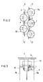
- the partition shown in Figure 1 is arranged inside a cylindrical crusher perpendicular to its longitudinal axis 1 of rotation. It comprises bars 2 rectilinear and parallel to each other, fixed at their two ends to the support 3 by bolts 4.
- the support 3 is itself fixed, by means not shown, to the shell 5 of the cylindrical crusher.
- each bar 2 is a solid metal cylinder, 90 mm in diameter, the ends of which are bevelled to follow the annular curvature of the support 2.
- Figure 2 shows the arrangement of bars 2 along the two rows.
- the bars 2a of the first row are aligned in the same direction DD 'perpendicular to longitudinal axis 1 of the mill.
- the bars 2 b of the second row are aligned in the same direction EE ′ parallel to the direction DD ′.
- Figure 2 also shows the method of fixing a bar 2 on the support 3. The end of the bar 2 is notched on the one hand so as to apply flat on the adjustment plate 6 and on the other leaves so as to receive the head of the bolt 7.
- the end of the bar 2 and the plate 6 are pierced with a smooth hole; the support 3 is pierced with a threaded orifice; bolt 7 passes through the smooth hole and the tapped hole and keeps blocked by the bolt 7, the bar 2, the plate 6 and the support 3.
- the spacing between the two rows that is to say between the two directions DD ′ and EE ′ is around 90 to 115 mm.
- the spacing between two adjacent bars of the same row 2 a or 2 b is 30 mm.
- the spacing between two adjacent bars, one belonging to the first row 2 a and the other to the second row 2 b, is 25 mm. It is this latter spacing which constitutes the width of the lumen passing the material through the partition. This spacing is a function of the diameter of the balls or dimensions of the smallest grinding bodies. To vary this spacing, it is sufficient to interpose between the support 3 and the bars 2 of the adjustment plates 6 of a different thickness.
- one or more stiffening elements placed between the two rows of bars are placed, the cross section of which is in the form of a cross and on which the bars of the two rows are supported. sort of maintaining a constant spacing between them despite the forces exerted during the operation of the mill.
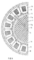
- the annular support 3, shown in Figure 1 has a structure called open lantern, it is constituted by the assembly by welding of elements of smaller dimensions, which are metal plates with large openings 9, thick 60 mm, in the form of arcs, so as to match the inner part of the ferrule 5.
- the support 3 is lined with wear plates 10 which can be solid or perforated.
- the thickness of these plates is defined by the alignment of these with bars 2 a and 2 b .
- the height of these plates delimits an area of the partition through which the material cannot pass.
- the balls placed on either side of the partition in their respective compartment are spherical balls of diameter 110 and 100 mm on one side and 90, 80, 70 and 60 mm on the other.
- the circular shape of the section of the bars 2 or possibly elliptical is capable of causing the lowest pressure drop both for the passage of the material and for the flow of the ventilation air in the grinder.
- Each bar 11 consists of two bar sections 11 a and 11 b fixed at one end 12 on the annular support 13 and the other end 14 of which is housed free in an intermediate support 15.
- This support 15 consists of two notched shells , which are bolted together after positioning the ends 14 of the sections 11a and 11b in each of the corresponding notches.
- the bar sections 11a and 11b can move in the notches under the effect of the stresses inherent in grinding without deformation of the partition itself.
- a circular wear part 16 made of several removable elements covers the part corresponding to the fixing of the bars 11 on the annular support 13.
- the wear plates 17 which protect the annular support are placed on either side of said support and bolted together by bolts 18 passing through.
- the support is pierced with openings in which grids are housed 19.
- the wear plates 17 are pierced with openings which face those of the support and whose dimensions are slightly smaller than those of the support openings, thereby ensuring the maintenance of the grids 19 by simple locking.
Landscapes
- Engineering & Computer Science (AREA)
- Food Science & Technology (AREA)
- Crushing And Grinding (AREA)
- Crushing And Pulverization Processes (AREA)
- Combined Means For Separation Of Solids (AREA)
Claims (9)
Priority Applications (1)
| Application Number | Priority Date | Filing Date | Title |
|---|---|---|---|
| AT89401985T ATE76333T1 (de) | 1988-07-12 | 1989-07-11 | Trennungswand fuer eine zylindrische kugelmuehle. |
Applications Claiming Priority (2)
| Application Number | Priority Date | Filing Date | Title |
|---|---|---|---|
| FR8809751A FR2634142A1 (fr) | 1988-07-12 | 1988-07-12 | Cloison de separation d'un broyeur cylindrique a boulets |
| FR8809751 | 1988-07-12 |
Publications (3)
| Publication Number | Publication Date |
|---|---|
| EP0351305A2 EP0351305A2 (de) | 1990-01-17 |
| EP0351305A3 EP0351305A3 (en) | 1990-10-10 |
| EP0351305B1 true EP0351305B1 (de) | 1992-05-20 |
Family
ID=9368552
Family Applications (1)
| Application Number | Title | Priority Date | Filing Date |
|---|---|---|---|
| EP89401985A Expired - Lifetime EP0351305B1 (de) | 1988-07-12 | 1989-07-11 | Trennungswand für eine zylindrische Kugelmühle |
Country Status (6)
| Country | Link |
|---|---|
| EP (1) | EP0351305B1 (de) |
| AT (1) | ATE76333T1 (de) |
| DE (1) | DE68901591D1 (de) |
| ES (1) | ES2033109T3 (de) |
| FR (1) | FR2634142A1 (de) |
| GR (1) | GR3005278T3 (de) |
Families Citing this family (2)
| Publication number | Priority date | Publication date | Assignee | Title |
|---|---|---|---|---|
| CN107670782A (zh) * | 2017-11-13 | 2018-02-09 | 盐城吉达环保设备有限公司 | 一种球磨机磨内均风装置 |
| CN109926166A (zh) * | 2019-04-28 | 2019-06-25 | 四川省星船城水泥股份有限公司 | 一种球磨机隔舱组件及球磨机 |
Family Cites Families (6)
| Publication number | Priority date | Publication date | Assignee | Title |
|---|---|---|---|---|
| US1362334A (en) * | 1919-03-10 | 1920-12-14 | Frank E Marcy | Ball-mill |
| US1444101A (en) * | 1922-05-27 | 1923-02-06 | Worthington Pump & Mach Corp | Tube mill |
| SU623579A1 (ru) * | 1977-02-24 | 1978-09-15 | Государственный Всесоюзный Научно-Исследовательский Институт Цементной Промышленности "Ниицемент" | Межкамерна перегородка трубной мельницы |
| SU795560A1 (ru) * | 1979-03-21 | 1981-01-15 | Белгородский Технологическийинститут Строительных Материалов | Межкамерна перегородка дл ТРубНыХ МЕльНиц |
| DE3023311A1 (de) * | 1980-06-21 | 1982-01-14 | Draiswerke Gmbh, 6800 Mannheim | Kugelmuehle mit entleerungseinrichtung |
| SU1031506A1 (ru) * | 1982-03-24 | 1983-07-30 | Белгородский технологический институт строительных материалов им.И.А.Гришманова | Межкамерна перегородка |
-
1988
- 1988-07-12 FR FR8809751A patent/FR2634142A1/fr not_active Withdrawn
-
1989
- 1989-07-11 DE DE8989401985T patent/DE68901591D1/de not_active Expired - Lifetime
- 1989-07-11 EP EP89401985A patent/EP0351305B1/de not_active Expired - Lifetime
- 1989-07-11 ES ES198989401985T patent/ES2033109T3/es not_active Expired - Lifetime
- 1989-07-11 AT AT89401985T patent/ATE76333T1/de not_active IP Right Cessation
-
1992
- 1992-07-29 GR GR920401608T patent/GR3005278T3/el unknown
Also Published As
| Publication number | Publication date |
|---|---|
| EP0351305A3 (en) | 1990-10-10 |
| FR2634142A1 (fr) | 1990-01-19 |
| ES2033109T3 (es) | 1993-03-01 |
| EP0351305A2 (de) | 1990-01-17 |
| ATE76333T1 (de) | 1992-06-15 |
| GR3005278T3 (de) | 1993-05-24 |
| DE68901591D1 (de) | 1992-06-25 |
Similar Documents
| Publication | Publication Date | Title |
|---|---|---|
| EP0392919B1 (de) | Brennstabbündelfussstück mit Teilchenfangvorrichtung und Brennstabbündel mit einem solchen Fussstück | |
| FR2511895A1 (fr) | Plaque de support de l'element de filtration d'une centrifugeuse | |
| EP0998353A1 (de) | Rohrmühle | |
| EP0282842A1 (de) | Kolbenanordnung für hydraulische Stossdämpfer | |
| FR2936767A1 (fr) | Palier a roulement, notamment pour colonne de direction. | |
| EP1634021B1 (de) | Ringförmige brennkammer einer turbomaschine | |
| EP0351305B1 (de) | Trennungswand für eine zylindrische Kugelmühle | |
| FR2577245A1 (fr) | Cylindre ouvreur pour l'ouverture de balles de matieres fibreuses, telles que coton et fibres artificielles | |
| FR2478235A1 (fr) | Tricone a molettes coniques | |
| EP2904889A1 (de) | Rad, das ein verbessertes landwirtschaftliches gerät bildet | |
| EP0274935A1 (de) | Stossdämpfer für das hydropneumatische Federungselement eines Kraftfahrzeugs | |
| FR2881467A1 (fr) | Dispositif de distribution variable d'arbre a cames avec verrouillage sans jeu | |
| EP3822500B1 (de) | Lager für eine fachbildemaschine oder bewegungsübertragungssystem, hebel mit schaftmaschinenmechanik, der ein solches lager umfasst, und fachbildemaschine mit einem solchen hebel oder lager | |
| WO1992016297A1 (fr) | Cloison pour broyeur cylindrique a boulets a plusieurs niveaux de relevage de matieres | |
| FR2632327A1 (fr) | Machine a laver le linge | |
| FR2749381A1 (fr) | Projectile explosif | |
| EP3993944B1 (de) | Method of manufacturing a spray wall | |
| FR2708483A1 (fr) | Plaque de blindage à clavettes sphériques pour broyeur à boulets. | |
| FR2565850A1 (fr) | Paroi a fentes pour broyeur tubulaire | |
| FR3098263A1 (fr) | Procédé de montage ET ensemble mécanique COMPORTANT DES CORPS ROULANTS SÉPARÉS PAR DES ENTRETOISES INDIVIDUELLES | |
| FR2476773A1 (fr) | Systeme de montage hydrostatique | |
| WO1992016298A1 (fr) | Cloison pour broyeur a boulets comportant des lumieres anti-colmatantes | |
| FR2681112A1 (fr) | Cage de roulement a rouleaux guidee par les rouleaux. | |
| WO2021053015A1 (fr) | Méthode et ensemble de réparation d'un générateur de vapeur d'un réacteur nucléaire | |
| EP0402253A1 (de) | Kontinuierliche Einschneckenpresse mit anpassbarem Verdichtungsverhältnis |
Legal Events
| Date | Code | Title | Description |
|---|---|---|---|
| PUAI | Public reference made under article 153(3) epc to a published international application that has entered the european phase |
Free format text: ORIGINAL CODE: 0009012 |
|
| AK | Designated contracting states |
Kind code of ref document: A2 Designated state(s): AT BE CH DE ES FR GB GR IT LI LU NL SE |
|
| PUAL | Search report despatched |
Free format text: ORIGINAL CODE: 0009013 |
|
| AK | Designated contracting states |
Kind code of ref document: A3 Designated state(s): AT BE CH DE ES FR GB GR IT LI LU NL SE |
|
| 17P | Request for examination filed |
Effective date: 19900908 |
|
| 17Q | First examination report despatched |
Effective date: 19911017 |
|
| GRAA | (expected) grant |
Free format text: ORIGINAL CODE: 0009210 |
|
| ITF | It: translation for a ep patent filed | ||
| AK | Designated contracting states |
Kind code of ref document: B1 Designated state(s): AT BE CH DE ES FR GB GR IT LI LU NL SE |
|
| REF | Corresponds to: |
Ref document number: 76333 Country of ref document: AT Date of ref document: 19920615 Kind code of ref document: T |
|
| PGFP | Annual fee paid to national office [announced via postgrant information from national office to epo] |
Ref country code: AT Payment date: 19920624 Year of fee payment: 4 |
|
| REF | Corresponds to: |
Ref document number: 68901591 Country of ref document: DE Date of ref document: 19920625 |
|
| GBT | Gb: translation of ep patent filed (gb section 77(6)(a)/1977) | ||
| PGFP | Annual fee paid to national office [announced via postgrant information from national office to epo] |
Ref country code: CH Payment date: 19920708 Year of fee payment: 4 |
|
| PGFP | Annual fee paid to national office [announced via postgrant information from national office to epo] |
Ref country code: ES Payment date: 19920715 Year of fee payment: 4 |
|
| PGFP | Annual fee paid to national office [announced via postgrant information from national office to epo] |
Ref country code: LU Payment date: 19920722 Year of fee payment: 4 Ref country code: DE Payment date: 19920722 Year of fee payment: 4 |
|
| PGFP | Annual fee paid to national office [announced via postgrant information from national office to epo] |
Ref country code: SE Payment date: 19920724 Year of fee payment: 4 |
|
| PGFP | Annual fee paid to national office [announced via postgrant information from national office to epo] |
Ref country code: NL Payment date: 19920731 Year of fee payment: 4 Ref country code: GR Payment date: 19920731 Year of fee payment: 4 |
|
| PGFP | Annual fee paid to national office [announced via postgrant information from national office to epo] |
Ref country code: BE Payment date: 19920812 Year of fee payment: 4 |
|
| EPTA | Lu: last paid annual fee | ||
| REG | Reference to a national code |
Ref country code: GR Ref legal event code: FG4A Free format text: 3005278 |
|
| REG | Reference to a national code |
Ref country code: ES Ref legal event code: FG2A Ref document number: 2033109 Country of ref document: ES Kind code of ref document: T3 |
|
| PLBE | No opposition filed within time limit |
Free format text: ORIGINAL CODE: 0009261 |
|
| STAA | Information on the status of an ep patent application or granted ep patent |
Free format text: STATUS: NO OPPOSITION FILED WITHIN TIME LIMIT |
|
| 26N | No opposition filed | ||
| PGFP | Annual fee paid to national office [announced via postgrant information from national office to epo] |
Ref country code: FR Payment date: 19930512 Year of fee payment: 5 |
|
| PG25 | Lapsed in a contracting state [announced via postgrant information from national office to epo] |
Ref country code: LU Free format text: LAPSE BECAUSE OF NON-PAYMENT OF DUE FEES Effective date: 19930711 Ref country code: GB Effective date: 19930711 Ref country code: AT Effective date: 19930711 |
|
| PG25 | Lapsed in a contracting state [announced via postgrant information from national office to epo] |
Ref country code: SE Effective date: 19930712 Ref country code: ES Free format text: LAPSE BECAUSE OF THE APPLICANT RENOUNCES Effective date: 19930712 |
|
| PG25 | Lapsed in a contracting state [announced via postgrant information from national office to epo] |
Ref country code: LI Effective date: 19930731 Ref country code: CH Effective date: 19930731 Ref country code: BE Effective date: 19930731 |
|
| BERE | Be: lapsed |
Owner name: CAMBIER BENJAMIN Effective date: 19930731 |
|
| PG25 | Lapsed in a contracting state [announced via postgrant information from national office to epo] |
Ref country code: GR Free format text: THE PATENT HAS BEEN ANNULLED BY A DECISION OF A NATIONAL AUTHORITY Effective date: 19940131 |
|
| PG25 | Lapsed in a contracting state [announced via postgrant information from national office to epo] |
Ref country code: NL Effective date: 19940201 |
|
| GBPC | Gb: european patent ceased through non-payment of renewal fee |
Effective date: 19930711 |
|
| NLV4 | Nl: lapsed or anulled due to non-payment of the annual fee | ||
| REG | Reference to a national code |
Ref country code: CH Ref legal event code: PL |
|
| PG25 | Lapsed in a contracting state [announced via postgrant information from national office to epo] |
Ref country code: DE Effective date: 19940401 |
|
| REG | Reference to a national code |
Ref country code: GR Ref legal event code: MM2A Free format text: 3005278 |
|
| EUG | Se: european patent has lapsed |
Ref document number: 89401985.0 Effective date: 19940210 |
|
| PG25 | Lapsed in a contracting state [announced via postgrant information from national office to epo] |
Ref country code: FR Effective date: 19950331 |
|
| REG | Reference to a national code |
Ref country code: FR Ref legal event code: ST |
|
| REG | Reference to a national code |
Ref country code: ES Ref legal event code: FD2A Effective date: 19991007 |
|
| PG25 | Lapsed in a contracting state [announced via postgrant information from national office to epo] |
Ref country code: IT Free format text: LAPSE BECAUSE OF NON-PAYMENT OF DUE FEES;WARNING: LAPSES OF ITALIAN PATENTS WITH EFFECTIVE DATE BEFORE 2007 MAY HAVE OCCURRED AT ANY TIME BEFORE 2007. THE CORRECT EFFECTIVE DATE MAY BE DIFFERENT FROM THE ONE RECORDED. Effective date: 20050711 |