EP0350620A1 - Method for manufacturing concrete sleepers for switch points - Google Patents
Method for manufacturing concrete sleepers for switch points Download PDFInfo
- Publication number
- EP0350620A1 EP0350620A1 EP89110388A EP89110388A EP0350620A1 EP 0350620 A1 EP0350620 A1 EP 0350620A1 EP 89110388 A EP89110388 A EP 89110388A EP 89110388 A EP89110388 A EP 89110388A EP 0350620 A1 EP0350620 A1 EP 0350620A1
- Authority
- EP
- European Patent Office
- Prior art keywords
- holes
- formwork
- sleepers
- parts
- bores
- Prior art date
- Legal status (The legal status is an assumption and is not a legal conclusion. Google has not performed a legal analysis and makes no representation as to the accuracy of the status listed.)
- Granted
Links
- 238000000034 method Methods 0.000 title claims abstract description 33
- 238000004519 manufacturing process Methods 0.000 title claims abstract description 20
- 239000004567 concrete Substances 0.000 title claims description 9
- 238000009415 formwork Methods 0.000 claims description 25
- 241001669679 Eleotris Species 0.000 claims description 10
- 238000009434 installation Methods 0.000 claims description 9
- 238000005553 drilling Methods 0.000 claims description 6
- 239000000463 material Substances 0.000 claims description 2
- 239000002184 metal Substances 0.000 claims description 2
- 229910052751 metal Inorganic materials 0.000 claims description 2
- 239000002313 adhesive film Substances 0.000 claims 1
- 238000010276 construction Methods 0.000 abstract 2
- 238000003780 insertion Methods 0.000 abstract 1
- 230000037431 insertion Effects 0.000 abstract 1
- 229910000831 Steel Inorganic materials 0.000 description 2
- 239000010959 steel Substances 0.000 description 2
- 239000011178 precast concrete Substances 0.000 description 1
- 238000007789 sealing Methods 0.000 description 1
Images


Classifications
-
- E—FIXED CONSTRUCTIONS
- E01—CONSTRUCTION OF ROADS, RAILWAYS, OR BRIDGES
- E01B—PERMANENT WAY; PERMANENT-WAY TOOLS; MACHINES FOR MAKING RAILWAYS OF ALL KINDS
- E01B7/00—Switches; Crossings
- E01B7/22—Special sleepers for switches or crossings; Fastening means therefor
-
- B—PERFORMING OPERATIONS; TRANSPORTING
- B28—WORKING CEMENT, CLAY, OR STONE
- B28B—SHAPING CLAY OR OTHER CERAMIC COMPOSITIONS; SHAPING SLAG; SHAPING MIXTURES CONTAINING CEMENTITIOUS MATERIAL, e.g. PLASTER
- B28B23/00—Arrangements specially adapted for the production of shaped articles with elements wholly or partly embedded in the moulding material; Production of reinforced objects
- B28B23/005—Arrangements specially adapted for the production of shaped articles with elements wholly or partly embedded in the moulding material; Production of reinforced objects with anchoring or fastening elements for the shaped articles
Definitions
- the invention relates to a method as described in the preamble of claims 1, 7 and 8 and means for performing these methods.
- Formwork for series prefabricated parts made of concrete are usually very stable and expensive to manufacture because of the high production numbers. This is particularly true for turnout sleepers manufactured one after the other in the fitted bed. These also place very high demands on the dimensionally accurate position of the built-in parts.
- the built-in parts are therefore fixed in bores in the formwork, which are measured extremely precisely.
- the built-in parts - dowels or pipe sleeves for the rail fastening screws - are on the top of the sleepers.
- the top of the threshold lies in the formwork on the formwork floor.
- the base plate thus serves as a template for the installation of the built-in parts.
- a drilling grid is often used for large series.
- the templates to be produced for each type of threshold therefore have little influence on the costs for the individual threshold. With a small number of sleepers being manufactured, the cost of the floor panels serving as templates for the built-in parts can jeopardize the economics of manufacture.
- the invention has for its object to develop methods according to which a floor panel of a prestressed bed formwork for the production of small series of switch sleepers made of concrete with different arrangement of the built-in parts can be used repeatedly.
- the object is achieved by the measures specified in the characterizing part of claims 1, 7 and 8.
- Refinements of the methods are specified in subclaims 2 and 9 to 14.
- Means for carrying out the invention relate to claims 3 to 6 and 15 to 17. Claims 1, 7 and 8 describe three solutions to the problem set.
- Claim 1 describes a simple solution, according to which the floor panel is drilled on site or after removal for the production of a further threshold type with the associated hole combination. This process still requires considerable labor costs.
- the holes not used spans the thin cover according to the invention from a tough material due to the selected thickness and strength under concrete pressure without damage. It is newly manufactured for each new type of precast element and can be manufactured with little effort.
- the markings for the positions of the built-in parts can be drawn on it with computer help, so that the cover can already serve as a template for the holes.
- the production of such a cover from thin sheet metal, plastic or synthetic paper is considerably less expensive than a new production of the steel floor plate for the formwork.
- the floor panel is drilled from the outset with the bores of all types of prefabricated parts for which it is to be used, in one operation - if possible electronically program-controlled - before installation in the formwork and by grafting - for. B. temporarily closed by plastic or by filling.
- the bores in the floor panel required for the respective production of a certain type of sleeper must be found, opened and filled with holding devices for the built-in parts - in this case the pipe sleeves.
- This searching can be done according to claim 10 with search templates or also by electronically program-controlled devices.
- the method according to claim 7 avoids later drilling work on the floor panel, but limits its use to the types of sleepers with whose hole combinations it is drilled.
- a method according to claims 8 and 9 is completely independent of a prior definition of the threshold types.
- the floor panel is provided with holes or a continuous one in a fixed grid - expediently on the central axis and / or axes parallel to this and at equal intervals Provided slot.
- the application of the method according to claims 8 and 9 therefore requires u.
- U. on the rib plates small deviations of the holes from the central axis, namely to the extent that during the manufacture of the threshold no grid hole of the floor panel can be directly covered by a hole arranged in the central axis of the rib plate.
- the length of several finished parts or the entire fitted bed can be according to the method according to claims 8 or 9 be covered by formwork sheets according to claims 16 and 17, respectively.
- the parking devices are placed on the floor panel.
- the method according to claims 8 and 9 enables automation of the installation of the parking devices and the built-in parts in the formwork.
- turnout sleepers 2 are produced in series between side formwork on floor panels 3. Thresholds arranged one behind the other are delimited by parking devices 9 in the formwork. Bores 4 fix the position of built-in parts 5 in the switch sleepers 2 in the floor plates 3.
- Figures 2 and 3 show a cover 6 of the floor panel 3 according to claim 1, on which the associated new positions of the built-in parts are marked.
- This cover 6, for example glued on, covers the bores 7 of the floor panel 3 from previous uses.
- the holes 9 of the hole combinations for the positions of the built-in parts of the new use are made congruently in the base plate 3 through the cover 6.
- the bottom plate 3 according to claim 7 in the example shown in Figures 2 and 3 has the holes A1-A m , B1-B n , C1-C r , etc.
- the floor panel 3 only covers the length of a threshold in the fitted bed. Parking devices 9 are inserted between the floor plates 3.
- the search template 10 is adjusted with the aid of alignment marks 11, which are marked both on the base plate and on the search template.
- the holes B1-B m belonging to the threshold type B are indicated in the vicinity of the other holes A1-A m , C1 C r etc. and are particularly marked. They can thus be clearly found in the vicinity of the other bores and the plugs can be removed from these bores and the holding devices for the tube sleeves can be installed.
- FIGS. 4 and 5 show a continuous base plate 21 provided with bores 25 in a fixed grid.
- the bores 25 are arranged in the central axis 26 at an equal distance from one another.
- a search template 14 is adjusted on the base plate 21 with the aid of alignment marks 15, which are marked both on the base plate 21 and on the search template 14.
- the holes K1-K m belonging to the threshold type K are indicated in the vicinity of the other other threshold types associated holes I1-I m , L1-L r etc. and are particularly marked. They can thus be found out clearly from the other bores, freed of the sealing plug and filled with tube sleeves or holding devices for the installation of the tube sleeves. In the same way, the holes 22 required to fix the parking devices 9 are sought.
- the outline 16 of a specially drilled rib plate 17 is entered according to claim 15.
- the bores 23, 24 are not on the central axis 18 of the rib plate 17, but about the dimensions 19, 20 which differ as a rule, except for the axis, in order to come into congruence with the associated grid bores K 1, K 2.
Landscapes
- Engineering & Computer Science (AREA)
- Mechanical Engineering (AREA)
- Manufacturing & Machinery (AREA)
- Chemical & Material Sciences (AREA)
- Ceramic Engineering (AREA)
- Architecture (AREA)
- Civil Engineering (AREA)
- Structural Engineering (AREA)
- Manufacturing Of Tubular Articles Or Embedded Moulded Articles (AREA)
- Moulds, Cores, Or Mandrels (AREA)
- Devices For Post-Treatments, Processing, Supply, Discharge, And Other Processes (AREA)
- Curing Cements, Concrete, And Artificial Stone (AREA)
- Manufacture Of Switches (AREA)
- Tumbler Switches (AREA)
- Forms Removed On Construction Sites Or Auxiliary Members Thereof (AREA)
- Seal Device For Vehicle (AREA)
- Crystals, And After-Treatments Of Crystals (AREA)
- Compositions Of Macromolecular Compounds (AREA)
- Preparation Of Compounds By Using Micro-Organisms (AREA)
Abstract
Description
Die Erfindung betrifft ein Verfahren, wie es im Oberbegriff der Ansprüche 1, 7 und 8 beschrieben ist und Mittel zur Durchführung dieser Verfahren.
Schalungen für Serienfertigteile aus Beton werden in der Regel wegen der hohen Fertigungszahlen sehr stabil und aufwendig hergestellt. Dies trifft im besonderen Maße für im Spannbett hintereinander hergestellte Weichenschwellen zu. Bei diesen werden zusätzlich sehr hohe Anforderungen an eine maßgenaue Lage der Einbauteile gestellt. Die Einbauteile werden deshalb in Bohrungen in der Schalung fixiert, die äußerst genau eingemessen werden.The invention relates to a method as described in the preamble of
Formwork for series prefabricated parts made of concrete are usually very stable and expensive to manufacture because of the high production numbers. This is particularly true for turnout sleepers manufactured one after the other in the fitted bed. These also place very high demands on the dimensionally accurate position of the built-in parts. The built-in parts are therefore fixed in bores in the formwork, which are measured extremely precisely.
Bei Schwellen liegen die Einbauteile - Dübel oder Rohrhülsen für die Schienenbefestigungsschrauben - auf der Oberseite der Schwelle. Die Oberseite der Schwelle liegt in der Schalung auf dem Schalungsboden. Das Bodenblech dient somit als Schablone für den Einbau der Einbauteile.
Bei großen Serien wird ein Bohrraster oft benutzt. Die für jeden Schwellentyp herzustellenden Schablonen beeinflussen deshalb die Kosten für die Einzelschwelle nur wenig. Bei geringen Herstellungszahlen eines Schwellentyps können die Kosten für die als Schablonen für die Einbauteile dienenden Bodenbleche die Wirtschaftlichkeit der Fertigung in Frage stellen.In sleepers, the built-in parts - dowels or pipe sleeves for the rail fastening screws - are on the top of the sleepers. The top of the threshold lies in the formwork on the formwork floor. The base plate thus serves as a template for the installation of the built-in parts.
A drilling grid is often used for large series. The templates to be produced for each type of threshold therefore have little influence on the costs for the individual threshold. With a small number of sleepers being manufactured, the cost of the floor panels serving as templates for the built-in parts can jeopardize the economics of manufacture.
Besonders kompliziert ist das Herstellen der Bohrungen in Weichenschwellenschablonen. Bei normalen Gleisschwellen kreuzen die Schienenachsen die Schwelle senkrecht. Die Einbauteile für die Befestigung der Schienen auf der Schwelle und entsprechend die sie auf dem Bodenblech der Schalung fixierenden Bohrungen liegen deshalb bei normalen Gleisschwellen auf der Mittelachse. Anders bei Weichenschwellen: Hier kreuzen die Schienenachsen unter verschiedenen in der Regel nicht rechten Winkeln die Schwellenachsen. Bisher wurden für die Befestigung auch der nicht rechtwinklig kreuzenden Schienenstränge in Achse gebohrte Rippenplatten verwendet, was in zahlreichen Achsen über die Schwellenoberfläche verstreut angeordneten Einbauteilen für die Rippenplatten-Befestigungsschrauben und entsprechende Bohrungen zur Fixierung der Einbauteile im Bodenblech der Schalung erforderte. Eine Schalung für Weichenschwellen aus Beton ist aus der DE 3440247 bekannt. Diese Schalung weist ein stählernes Bodenblech auf, das paßgenau zwischen Seitenteilen eingelassen ist. Das Anfertigen mit Bohrungen an anderer Stelle versehener neuer Bodenbleche und deren Einbau sind aufwendig.It is particularly complicated to make the holes in switch sleeper templates. With normal track sleepers, the rail axes cross the sleeper vertically. The installation parts for fastening the rails to the sleeper and, correspondingly, the holes that fix them on the floor panel of the formwork therefore lie on the central axis of normal track sleepers. The situation is different for turnout sleepers: here the rail axes cross the threshold axes at different, generally not right angles. Up to now, ribbed plates drilled in the axis have been used for the fastening of the non-perpendicularly crossing rail sections, which required installation parts for the ribbed plate fastening screws and corresponding bores for fixing the installation parts in the floor plate of the formwork in numerous axes. A formwork for switch sleepers made of concrete is known from DE 3440247. This formwork has a steel floor panel, which is embedded precisely between side parts. The production of new floor plates with holes drilled elsewhere and their installation are complex.
Der Erfindung liegt die Aufgabe zugrunde, Verfahren zu entwickeln, nach denen ein Bodenblech einer Spannbettschalung für die Herstellung kleiner Serien von Weichenschwellen aus Beton mit unterschiedlicher Anordnung der Einbauteile wiederholt verwendbar ist. Die Aufgabe wird durch die im kennzeichnenden Teil der Ansprüche 1, 7 und 8 angegebenen Maßnahmen gelöst. Ausgestaltungen der Verfahren sind in den Unteransprüchen 2 sowie 9 bis 14 angegeben. Mittel zur Durchführung der Erfindung betreffen die Ansprüche 3 bis 6 sowie 15 bis 17. Die Ansprüche 1, 7 und 8 beschreiben drei Lösungen der gestellten Aufgabe.The invention has for its object to develop methods according to which a floor panel of a prestressed bed formwork for the production of small series of switch sleepers made of concrete with different arrangement of the built-in parts can be used repeatedly. The object is achieved by the measures specified in the characterizing part of
Anspruch 1 beschreibt eine einfache Lösung, nach der das Bodenblech für die Fertigung eines weiteren Schwellentyps mit der zugehörigen Lochkombination vor Ort oder nach Ausbau gebohrt wird. Dieser Arbeitsgang erfordert noch erhebliche Lohnkosten. Die nicht verwendeten Bohrungen überspannt die erfindungsgemäße dünne Abdeckung aus einem zähen Material auf Grund der gewählten Dicke und Festigkeit unter Betonierdruck schadlos. Sie wird für jeden neuen Fertigteiltyp neu angefertigt und ist ohne großen Aufwand herstellbar. Die Markierungen für die Positionen der Einbauteile können mit Computerhilfe auf ihr eingezeichnet werden, so daß die Abdeckung bereits für die Bohrungen als Schablone dienen kann. Die Anfertigung einer solchen Abdeckung aus dünnem Blech, Kunststoff oder synthetischem Papier ist erheblich kostengünstiger als eine Neuanfertigung des stählernen Bodenblechs für die Schalung.
Durch das Verfahren nach Anspruch 7 wird das Bodenblech von vornherein mit den Bohrungen aller Fertigteiltypen, für die es eingesetzt werden soll, in einem Arbeitsgang - möglichst elektronisch programmgesteuert - vor dem Einbau in die Schalung gebohrt und durch Pfropfen - z. B. aus Kunststoff- oder durch eine Spachtelung provisorisch geschlossen. In einem zweiten Arbeitsgang müssen dann die für die jeweilige Fertigung eines bestimmten Schwellentyps erforderlichen Bohrungen im Bodenblech aufgesucht, geöffnet und mit Haltevorrichtungen für die Einbauteile - in diesem Fall die Rohrhülsen - besetzt werden. Dieses Aufsuchen kann nach Anspruch 10 mit Suchschablonen oder auch durch elektronisch programmgesteuerte Vorrichtungen geschehen. Das Verfahren nach Anspruch 7 vermeidet spätere Bohrarbeiten am Bodenblech, beschränkt jedoch seine Verwendung auf die Schwellentypen, mit deren Lochkombinationen es verbohrt ist.By the method according to
Völlig unabhängig von einer vorherigen Festlegung der Schwellentypen ist man bei einem Verfahren entsprechend den Ansprüchen 8 und 9. Das Bodenblech wird in einem festgelegten Raster - zweckmäßig auf der Mittelachse und/oder zu dieser parallelen Achsen und in gleichen Abständen - mit Bohrungen bzw. einem durchlaufenden Schlitz versehen. Damit können die Haltevorrichtungen für die Rohrhülsen in der Weichenschwelle und die Verschraubungen für die Rippenplatten nur noch an bestimmten Punkten der Weichenschwelle angeordnet werden. Diese Punkte müssen nicht unbedingt Punkte sein, die in Längsachse der Rippenplatte liegen.
Die Anwendung des Verfahrens nach den Ansprüchen 8 und 9 erfordert daher u. U. an den Rippenplatten geringe Abweichungen der Bohrungen aus der Mittelachse, nämlich insoweit, als bei der Fertigung der Schwelle keine Rasterbohrung des Bodenblechs unmittelbar von einer in Mittelachse der Rippenplatte angeordneten Bohrung abdeckbar ist.A method according to
The application of the method according to
Gegenüber dem Verfahren nach Anspruch 7, bei dem durch ein Schalungsblech jeweils nur die Länge eines Fertigteils im Spannbett abgedeckt wird und die Schalungsbleche durch Abstellvorrichtungen getrennt sind, kann nach den Verfahren nach den Ansprüchen 8 bzw. 9 die Länge von mehreren Fertigteilen oder des ganzen Spannbetts durch Schalungsbleche nach den Ansprüchen 16 bzw. 17 abgedeckt werden. Die Abstellvorrichtungen werden in diesem Fall auf das Bodenblech aufgesetzt. Durch die Verfahren nach den Ansprüchen 8 und 9 wird eine Automatisierung des Einbaus der Abstellvorrichtungen und der Einbauteile in die Schalung ermöglicht.Compared to the method according to
Die Erfindung wird durch die Fig. 1 bis 8 erläutert. Es zeigen:
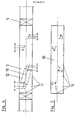
- Fig. 1 ein Spannbett mit hergestellten Serienfertigteilen im Schnitt,
- Fig. 2 eine auf das Bodenblech aufgeklebte Abdeckung nach
Anspruch 1 in der Aufsicht, Fig. 3 einen vertikalen Schnitt durch Abdeckung und - Bodenblech der Fig. 2,
- Fig. 4 eine Aufsicht auf ein nach
Anspruch 1 hergestelltes Bodenblech, - Fig. 5 die Suchschablone für einen bestimmten Weichenschwellentyp B, mit deren Hilfe die zu diesem Typ gehörigen Bohrungen aufgesucht, geöffnet und mit Haltevorrichtungen besetzt werden können,
- Fig. 6 eine Aufsicht auf ein nach
Anspruch 8 hergestelltes und nachAnspruch 16 durchlaufendes Bodenblech, - Fig. 7 die Suchschablone zum Aufsuchen und Öffnen der zu einem bestimmten Schwellentyp K in einem Bodenblech nach Fig. 6 gehörigen Bohrungen, in die dann die zugehörigen Haltevorrichtungen einsetzbar sind,
- Fig. 8 eine exzentrisch zur Längsachse gebohrte Rippenplatte nach
Anspruch 8.
- 1 a fitted bed with manufactured series parts in section,
- Fig. 2 is a glued to the floor panel cover according to
claim 1 in plan, Fig. 3 is a vertical section through cover and - 2,
- 4 is a plan view of a floor panel manufactured according to
claim 1, - 5 shows the search template for a specific turnout threshold type B, with the aid of which the holes belonging to this type can be searched for, opened and filled with holding devices,
- 6 is a plan view of a floor panel manufactured according to
claim 8 and continuous according toclaim 16, - 7 shows the search template for locating and opening the bores belonging to a certain threshold type K in a floor panel according to FIG. 6, into which the associated holding devices can then be inserted,
- 8 shows a rib plate drilled eccentrically to the longitudinal axis according to
claim 8.
In einer Fertigungsanlage 1 für Betonfertigteile im Spannbett werden Weichenschwellen 2 zwischen Seitenschalungen auf Bodenblechen 3 hintereinander hergestellt. Hintereinander angeordnete Schwellen werden durch Abstellvorrichtungen 9 in der Schalung abgegrenzt. In den Bodenblechen 3 fixieren Bohrungen 4 die Position von Einbauteilen 5 in den Weichenschwellen 2.In a
Die Figuren 2 und 3 zeigen eine Abdeckung 6 des Bodenblechs 3 nach Anspruch 1, auf der die zugehörigen neuen Positionen der Einbauteile markiert sind. Diese beispielsweise aufgeklebte Abdeckung 6 überdeckt die Bohrungen 7 des Bodenblechs 3 aus vorausgegangenen Verwendungen. An den vorher auf der Abdeckung 6 aufgebrachten Markierungen 8 werden durch die Abdeckung 6 hindurch deckungsgleich im Bodenblech 3 die Bohrungen 9 der Lochkombinationen für die Positionen der Einbauteile der neuen Verwendung hergestellt.Figures 2 and 3 show a
Das Bodenblech 3 nach Anspruch 7 im in den Figuren 2 und 3 dargestellten Beispiel weist die Bohrungen A₁-Am, B₁-Bn, C₁-Cr usw. auf. Das Bodenblech 3 deckt nur die Länge einer Schwelle im Spannbett ab. Zwischen den Bodenblechen 3 werden Abstellvorrichtungen 9 eingesetzt. Mit Hilfe einer Suchschablone 10 können die zu einem betimmten Schwellentyp B gehörigen Bohrungen B₁-Bn gefunden werden. Die Suchschablone 10 wird mit Hilfe von Justiermarken 11, die sowohl auf dem Bodenblech wie auch auf der Suchschablone markiert sind, einjustiert. Die zum Schwellentyp B gehörigen Bohrungen B₁-Bm sind im Umfeld der übrigen Bohrungen A₁-Am, C₁ Cr usw. angegeben und besonders gekennzeichnet. Sie sind somit im Umfeld der übrigen Bohrungen eindeutig auffindbar und die Pfropfen können aus diesen Bohrungen entfernt und die Haltevorrichtungen für die Rohrhülsen eingebaut werden.The
Auf dem Bohrraster des Bodenblechs 3 ist der Umriß 2 einer normalen in Längsachse 3 mit Bohrungen versehenen Rippenplatte eingetragen.On the drilling grid of the
Die Figuren 4 und 5 zeigen ein in festgelegtem Raster mit Bohrungen 25 versehenes durchlaufendes Bodenblech 21. Die Bohrungen 25 sind in der Mittelachse 26 mit untereinander gleichem Abstand angeordnet. Eine Suchschablone 14 wird mit Hilfe von Justiermarken 15, die sowohl auf dem Bodenblech 21 wie auf der Suchschablone 14 markiert sind, auf dem Bodenblech 21 einjustiert. Die zum Schwellentyp K gehörigen Bohrungen K₁-Km sind im Umfeld der übrigen anderen Schwellentypen zugeordneten Bohrungen I₁-Im, L₁-Lr usw. angegeben und besonders gekennzeichnet. Sie können so aus den übrigen Bohrungen eindeutig herausgefunden, von dem Verschlußpfropfen befreit und mit Rohrhülsen bzw. Haltevorrichtungen für den Einbau der Rohrhülsen besetzt werden. In gleicher Weise werden die zur Fixierung der Abstellvorrichtungen 9 erforderlichen Bohrungen 22 aufgesucht. Auf dem Bohrraster des Bodenblechs 21 ist der Umriß 16 einer besonders gebohrten Rippenplatte 17 nach Anspruch 15 eingetragen. Die Bohrungen 23,24 liegen nicht auf der Mittelachse 18 der Rippenplatte 17, sondern um die in der Regel differierenden Maße 19,20 außer der Achse, um mit den zugehörigen Rasterbohrungen K₁,K₂ in Deckung zu kommen.FIGS. 4 and 5 show a
Claims (17)
o daß das Bodenblech (3) vor seinem Einbau in die Schalung mit Bohrungen (A,B,C) für mehrere Schwellentypen versehen wird,
o daß die Bohrungen (A,B,C) durch geeignete Mittel provisorisch geschlossen werden und
o daß die zur Fertigung einer bestimmten Schwellentype benötigte Bohrungskombination mit bestimmten Suchverfahren gefunden und von ihrem provisorischen Verschluß befreit wird,7.Method for the production of turnout sleepers made of concrete in a prestressed bed formwork, the bottom plate of which has holes through which means can be passed, with which the holding devices for the installation parts are fixed in the sleeper surface during concreting, and for sleepers with different individual lengths and with different Arrangement of the built-in parts can be used repeatedly, characterized in that
o that the floor panel (3) is provided with holes (A, B, C) for several types of sleepers before it is installed in the formwork,
o that the holes (A, B, C) are temporarily closed by suitable means and
o that the combination of holes required to manufacture a certain type of sleeper is found using certain search methods and is freed from its provisional closure,
o daß das Bodenblech (21) mit in festgelegtem Raster - zweckmäßig mit auf der Längsachse (26) und/oder dazu parallelen Achsen - in bestimmtem Abstand mit Bohrungen (25) versehen wird,
o daß die Bohrungen (25) durch geeignete Mittel provisorisch geschlossen werden und
o daß die für die Fertigung einer bestimmten Fertigteiltype benötigte Bohrungskombination (K) mit bestimmten Suchverfahren gefunden und von dem provisorischen Verschluß befreit wird.8.Procedure for the production of turnout sleepers made of concrete in a prestressed bed formwork, the bottom plate of which has holes through which means can be passed, with which the holding devices for the components are fixed in the sleeper surface during concreting, and for sleepers with different individual lengths and with different Arrangement of the built-in parts can be used repeatedly, characterized in that
o that the base plate (21) is provided with bores (25) at a certain distance with a fixed grid - expediently with axes parallel to the longitudinal axis (26) and / or to it,
o that the bores (25) are temporarily closed by suitable means and
o that the bore combination (K) required for the production of a certain type of precast element is found using certain search methods and the temporary closure is removed.
o für jede Fertigteiltype eine Suchschablone (10,14) hergestellt wird, auf der alle in dem Bodenblech befindlichen Bohrungen (A,B,C bzw. J,K,L) enthalten und die zu dem bestimmten Fertigteiltyp gehörigen Bohrungen (B bzw. K) besonders gekennzeichnet sind,
o die Suchschablone (10,14) von Hand mit Hilfe von auf der Schablone und dem Bodenblech (3,21) übereinstimmend eingetragenen Markierungen (11,15) auf dem Bodenblech (3,21) ausgerichtet wird, wobei die Bohrbilder (B bzw. K) der Schablone mit den Bohrungen (B bzw. K) des Bodenblechs (3,21) in Deckung kommen und
o an den besonders gekennzeichneten Bohrpunkten (B bzw. K) der Suchschablone (10,14) die Verschlüsse aus den darunter liegenden provisorisch geschlossenen Bohrungen (B bzw. K) des Schalungsblechs ausgestoßen werden.10. The method according to any one of claims 7 or 8, characterized in that to find the hole combination required for the production of the floor panel (3,21) of a certain type of prefabricated part
o A search template (10, 14) is produced for each type of precast element, on which all the holes (A, B, C or J, K, L) in the base plate contain and the holes (B or K ) are specially marked,
o The search template (10, 14) is aligned by hand with the aid of markings (11, 15) on the base plate (3, 21) that are entered in the same manner on the template and the base plate (3, 21), the drilling patterns (B or K) of the template with the holes (B or K) of the floor plate (3.21) and cover
o at the specially marked drilling points (B or K) of the search template (10, 14) the closures are ejected from the temporarily closed holes (B or K) of the formwork sheet below.
Priority Applications (1)
| Application Number | Priority Date | Filing Date | Title |
|---|---|---|---|
| AT89110388T ATE75508T1 (en) | 1988-07-14 | 1989-06-08 | PROCESS FOR THE MANUFACTURE OF SWITCH SLEEPERS FROM CONCRETE. |
Applications Claiming Priority (2)
| Application Number | Priority Date | Filing Date | Title |
|---|---|---|---|
| DE3823860 | 1988-07-14 | ||
| DE3823860A DE3823860A1 (en) | 1988-05-04 | 1988-07-14 | Process for the repeated use of a metal sheet of a shuttering for series-produced precast concrete compound units with different arrangements of installation parts |
Publications (2)
| Publication Number | Publication Date |
|---|---|
| EP0350620A1 true EP0350620A1 (en) | 1990-01-17 |
| EP0350620B1 EP0350620B1 (en) | 1992-04-29 |
Family
ID=6358649
Family Applications (1)
| Application Number | Title | Priority Date | Filing Date |
|---|---|---|---|
| EP89110388A Expired - Lifetime EP0350620B1 (en) | 1988-07-14 | 1989-06-08 | Method for manufacturing concrete sleepers for switch points |
Country Status (10)
| Country | Link |
|---|---|
| US (1) | US5124093A (en) |
| EP (1) | EP0350620B1 (en) |
| AT (1) | ATE75508T1 (en) |
| DD (1) | DD300085A5 (en) |
| ES (1) | ES2012315T3 (en) |
| FI (1) | FI901261A0 (en) |
| NO (1) | NO894847L (en) |
| PT (1) | PT91143B (en) |
| RU (1) | RU2005598C1 (en) |
| WO (1) | WO1990000647A1 (en) |
Cited By (1)
| Publication number | Priority date | Publication date | Assignee | Title |
|---|---|---|---|---|
| CN101508144B (en) * | 2009-03-02 | 2011-03-23 | 深圳港创建材股份有限公司 | Concrete casting production technique with energy-saving environmental-protection function |
Families Citing this family (8)
| Publication number | Priority date | Publication date | Assignee | Title |
|---|---|---|---|---|
| US5301927A (en) * | 1988-07-14 | 1994-04-12 | Wayss & Freytag Aktiengesellschaft | Method of making concrete switch cross ties |
| US5227112A (en) * | 1988-07-14 | 1993-07-13 | Wayss & Freytag Aktiengesellschaft | Method of making concrete switch cross ties |
| DE4237466C2 (en) * | 1992-11-06 | 2002-01-17 | Dyckerhoff & Widmann Ag | Device for fastening a built-in part in a formwork for producing prefabricated components made of concrete |
| US5618476A (en) * | 1995-08-03 | 1997-04-08 | Mogel; Richard L. | Process for slip form production of prestressed concrete railroad ties |
| DE19726468A1 (en) * | 1997-06-21 | 1999-02-11 | Butzbacher Weichenbau Gmbh | Arrangement for attaching a track section |
| US5809732A (en) * | 1997-08-08 | 1998-09-22 | Ccc Group, Inc. | M/bed block system |
| AU2002953592A0 (en) * | 2002-12-30 | 2003-01-23 | John Spence Nominees Pty Ltd | Apparatus & method for panel construction |
| ES2257197B1 (en) * | 2004-11-02 | 2007-04-16 | Prefabricaciones Y Contratas, S.A.U. (Precon, S.A.U.) | IMPROVEMENTS INTRODUCED IN THE MANUFACTURE OF CONCRETE CROSSINGS FOR RAILWAY SYSTEMS. |
Citations (1)
| Publication number | Priority date | Publication date | Assignee | Title |
|---|---|---|---|---|
| US4495127A (en) * | 1982-07-09 | 1985-01-22 | A-Betong Ab | Method of manufacturing concrete sleeper blocks |
Family Cites Families (9)
| Publication number | Priority date | Publication date | Assignee | Title |
|---|---|---|---|---|
| DE133077C (en) * | ||||
| DE1584397C3 (en) * | 1964-07-15 | 1975-07-10 | Van Egteren Industriele Constructiebeton Maatschappij N.V., Hasselt (Niederlande) | Device for building molds, in particular for concrete elements, on a metal table |
| US3685783A (en) * | 1970-05-21 | 1972-08-22 | Maule Ind Inc | Insert for embedded fittings |
| US4102957A (en) * | 1975-11-20 | 1978-07-25 | Canfarge Ltd (Francon Division) | Apparatus and method for manufacturing prestressed concrete railway ties |
| US4242071A (en) * | 1978-08-14 | 1980-12-30 | Martin Concrete Engineering Company | Concrete railroad tie casting and handling system |
| SE415868B (en) * | 1978-12-05 | 1980-11-10 | A Betong Ab | SET TO MANUFACTURE CONCRETE SLIPPING BULK AND MATERIAL SETUP FOR EXECUTION OF THE SET |
| DE3440247A1 (en) * | 1984-11-03 | 1986-05-22 | Wayss & Freytag Ag, 6000 Frankfurt | SHUTTERING FOR PRE-FABRIC PRODUCTS IN STEEL CONCRETE, PRESERVED FOR PRELOAD TURNTABLE SLEEPERS |
| SU1256967A1 (en) * | 1985-02-21 | 1986-09-15 | Специальное Конструкторское Бюро Главмостостроя | Face-maker of mould for reinforced concrete products |
| FR2579512B1 (en) * | 1985-04-01 | 1987-06-19 | Rech Etudes Tech | PROCESS INSTALLATION FOR THE MANUFACTURE OF REINFORCED CONCRETE ELEMENTS, PARTICULARLY PRE-STRESSED CONCRETE SLABS OR PRELABS |
-
1989
- 1989-06-08 US US07/434,683 patent/US5124093A/en not_active Expired - Fee Related
- 1989-06-08 ES ES198989110388T patent/ES2012315T3/en not_active Expired - Lifetime
- 1989-06-08 AT AT89110388T patent/ATE75508T1/en not_active IP Right Cessation
- 1989-06-08 WO PCT/EP1989/000644 patent/WO1990000647A1/en active Application Filing
- 1989-06-08 EP EP89110388A patent/EP0350620B1/en not_active Expired - Lifetime
- 1989-07-12 PT PT91143A patent/PT91143B/en not_active IP Right Cessation
- 1989-07-13 DD DD330774A patent/DD300085A5/en unknown
- 1989-12-04 NO NO89894847A patent/NO894847L/en unknown
-
1990
- 1990-03-13 RU SU904743301A patent/RU2005598C1/en active
- 1990-03-14 FI FI901261A patent/FI901261A0/en not_active IP Right Cessation
Patent Citations (1)
| Publication number | Priority date | Publication date | Assignee | Title |
|---|---|---|---|---|
| US4495127A (en) * | 1982-07-09 | 1985-01-22 | A-Betong Ab | Method of manufacturing concrete sleeper blocks |
Non-Patent Citations (2)
| Title |
|---|
| DIE BUNDESBAHN, Band 9, September 1982, Seiten 647-650; H. SCHULTHEISS et al: "Erstmals bei der DB: Weiche auf Spannbetonschwellen" * |
| REVUE GENERALE DES CHEMINS DE FER, Februar 1986, Seiten 87-96, Gauthier-Villars, Paris, FR; J. OECONOMOS et al.: "Branchement deux voies sur plancher en béton précontraint" * |
Cited By (1)
| Publication number | Priority date | Publication date | Assignee | Title |
|---|---|---|---|---|
| CN101508144B (en) * | 2009-03-02 | 2011-03-23 | 深圳港创建材股份有限公司 | Concrete casting production technique with energy-saving environmental-protection function |
Also Published As
| Publication number | Publication date |
|---|---|
| NO894847D0 (en) | 1989-12-04 |
| PT91143A (en) | 1990-02-08 |
| EP0350620B1 (en) | 1992-04-29 |
| ES2012315A4 (en) | 1990-03-16 |
| ATE75508T1 (en) | 1992-05-15 |
| US5124093A (en) | 1992-06-23 |
| DD300085A5 (en) | 1992-05-21 |
| WO1990000647A1 (en) | 1990-01-25 |
| ES2012315T3 (en) | 1992-11-16 |
| NO894847L (en) | 1990-01-25 |
| FI901261A0 (en) | 1990-03-14 |
| RU2005598C1 (en) | 1994-01-15 |
| PT91143B (en) | 1995-07-03 |
Similar Documents
| Publication | Publication Date | Title |
|---|---|---|
| EP0584729B1 (en) | Drilling device for dowel holes | |
| EP0350620B1 (en) | Method for manufacturing concrete sleepers for switch points | |
| DE2245215C3 (en) | Thread ladder | |
| DE8435927U1 (en) | Angle spacer for laying tile panels with joint lines of a specified width | |
| DE3412441C2 (en) | Method and device for processing prefabricated components | |
| EP1118730A1 (en) | Reinforcement spacer for positioning reinforcing rods towards a form in a concrete construction | |
| DE19521262C2 (en) | Method of making a building board | |
| DE102019124308A1 (en) | Anchoring element and method for assembling an anchor rail in a concrete structure | |
| DE69909224T2 (en) | foundation block | |
| DE3823860A1 (en) | Process for the repeated use of a metal sheet of a shuttering for series-produced precast concrete compound units with different arrangements of installation parts | |
| DE2244007C2 (en) | Resiliently supported block mounted railway track - has adjoining blocks in continuous channels in rigid support surfaces embedded in synthetic resin | |
| DE60304415T2 (en) | Method and device for building masonry | |
| DE2949267C2 (en) | Door sill construction | |
| DE3313731C2 (en) | Process for the machine production of wall elements | |
| EP2470719A1 (en) | Method for tamping a track | |
| EP0171565B1 (en) | Method of stopping moisture mounting in brickwork | |
| DE3938721A1 (en) | Drainage channel system for prefab. concrete elements - uses clamping device and clamp bracket for element jointing | |
| DE2251475B2 (en) | Method for producing a supporting structure, in particular the superstructure of a bridge made of prestressed concrete | |
| AT373008B (en) | SOUND ABSORBER DEVICE FOR IN COMPONENTS, e.g. CONCRETE PANELS, PARALLEL VENTILATION CHANNELS, AND METHOD FOR THE PRODUCTION OF SUCH A SOUND ABSORBING DEVICE | |
| DE1813344A1 (en) | Device for the production of prefabricated rectangular building blocks | |
| DE9200896U1 (en) | Wall anchor system | |
| DD282587A7 (en) | DEVICE FOR INTRODUCING PROFILED CONCRETE COMPONENT INSERTS | |
| EP0092179A1 (en) | Embedding unit of paving stones for producing soil covers, and process for producing the paving units and soil covers | |
| DE29813963U1 (en) | Pipe bushing made of plastic for heating pipes for installation in ceilings | |
| DE4307452A1 (en) | Barrier layer for introduction into walls |
Legal Events
| Date | Code | Title | Description |
|---|---|---|---|
| PUAI | Public reference made under article 153(3) epc to a published international application that has entered the european phase |
Free format text: ORIGINAL CODE: 0009012 |
|
| AK | Designated contracting states |
Kind code of ref document: A1 Designated state(s): AT BE CH ES FR GB GR IT LI LU NL SE |
|
| GBC | Gb: translation of claims filed (gb section 78(7)/1977) | ||
| EL | Fr: translation of claims filed | ||
| 17P | Request for examination filed |
Effective date: 19900605 |
|
| 17Q | First examination report despatched |
Effective date: 19910531 |
|
| ITF | It: translation for a ep patent filed | ||
| GRAA | (expected) grant |
Free format text: ORIGINAL CODE: 0009210 |
|
| AK | Designated contracting states |
Kind code of ref document: B1 Designated state(s): AT BE CH ES FR GB GR IT LI LU NL SE |
|
| PG25 | Lapsed in a contracting state [announced via postgrant information from national office to epo] |
Ref country code: GR Free format text: LAPSE BECAUSE OF FAILURE TO SUBMIT A TRANSLATION OF THE DESCRIPTION OR TO PAY THE FEE WITHIN THE PRESCRIBED TIME-LIMIT Effective date: 19920429 |
|
| REF | Corresponds to: |
Ref document number: 75508 Country of ref document: AT Date of ref document: 19920515 Kind code of ref document: T |
|
| GBT | Gb: translation of ep patent filed (gb section 77(6)(a)/1977) | ||
| PG25 | Lapsed in a contracting state [announced via postgrant information from national office to epo] |
Ref country code: LU Free format text: LAPSE BECAUSE OF NON-PAYMENT OF DUE FEES Effective date: 19920630 |
|
| ET | Fr: translation filed | ||
| REG | Reference to a national code |
Ref country code: ES Ref legal event code: FG2A Ref document number: 2012315 Country of ref document: ES Kind code of ref document: T3 |
|
| PLBE | No opposition filed within time limit |
Free format text: ORIGINAL CODE: 0009261 |
|
| STAA | Information on the status of an ep patent application or granted ep patent |
Free format text: STATUS: NO OPPOSITION FILED WITHIN TIME LIMIT |
|
| PGFP | Annual fee paid to national office [announced via postgrant information from national office to epo] |
Ref country code: SE Payment date: 19930330 Year of fee payment: 5 |
|
| 26N | No opposition filed | ||
| PGFP | Annual fee paid to national office [announced via postgrant information from national office to epo] |
Ref country code: AT Payment date: 19930428 Year of fee payment: 5 |
|
| PGFP | Annual fee paid to national office [announced via postgrant information from national office to epo] |
Ref country code: GB Payment date: 19930506 Year of fee payment: 5 |
|
| PGFP | Annual fee paid to national office [announced via postgrant information from national office to epo] |
Ref country code: FR Payment date: 19930511 Year of fee payment: 5 |
|
| PGFP | Annual fee paid to national office [announced via postgrant information from national office to epo] |
Ref country code: BE Payment date: 19930512 Year of fee payment: 5 |
|
| PGFP | Annual fee paid to national office [announced via postgrant information from national office to epo] |
Ref country code: ES Payment date: 19930519 Year of fee payment: 5 |
|
| PGFP | Annual fee paid to national office [announced via postgrant information from national office to epo] |
Ref country code: NL Payment date: 19930630 Year of fee payment: 5 |
|
| PGFP | Annual fee paid to national office [announced via postgrant information from national office to epo] |
Ref country code: CH Payment date: 19930709 Year of fee payment: 5 |
|
| PG25 | Lapsed in a contracting state [announced via postgrant information from national office to epo] |
Ref country code: GB Effective date: 19940608 Ref country code: AT Effective date: 19940608 |
|
| PG25 | Lapsed in a contracting state [announced via postgrant information from national office to epo] |
Ref country code: SE Effective date: 19940609 Ref country code: ES Free format text: LAPSE BECAUSE OF THE APPLICANT RENOUNCES Effective date: 19940609 |
|
| PG25 | Lapsed in a contracting state [announced via postgrant information from national office to epo] |
Ref country code: LI Effective date: 19940630 Ref country code: CH Effective date: 19940630 Ref country code: BE Effective date: 19940630 |
|
| BERE | Be: lapsed |
Owner name: WAYSS & FREYTAG A.G. Effective date: 19940630 |
|
| PG25 | Lapsed in a contracting state [announced via postgrant information from national office to epo] |
Ref country code: NL Effective date: 19950101 |
|
| EUG | Se: european patent has lapsed |
Ref document number: 89110388.9 Effective date: 19950110 |
|
| GBPC | Gb: european patent ceased through non-payment of renewal fee |
Effective date: 19940608 |
|
| NLV4 | Nl: lapsed or anulled due to non-payment of the annual fee | ||
| PG25 | Lapsed in a contracting state [announced via postgrant information from national office to epo] |
Ref country code: FR Effective date: 19950228 |
|
| REG | Reference to a national code |
Ref country code: CH Ref legal event code: PL |
|
| EUG | Se: european patent has lapsed |
Ref document number: 89110388.9 |
|
| REG | Reference to a national code |
Ref country code: FR Ref legal event code: ST |
|
| REG | Reference to a national code |
Ref country code: ES Ref legal event code: FD2A Effective date: 19991007 |
|
| PG25 | Lapsed in a contracting state [announced via postgrant information from national office to epo] |
Ref country code: IT Free format text: LAPSE BECAUSE OF NON-PAYMENT OF DUE FEES;WARNING: LAPSES OF ITALIAN PATENTS WITH EFFECTIVE DATE BEFORE 2007 MAY HAVE OCCURRED AT ANY TIME BEFORE 2007. THE CORRECT EFFECTIVE DATE MAY BE DIFFERENT FROM THE ONE RECORDED. Effective date: 20050608 |