EP0349998A1 - Vertical blind assembly - Google Patents
Vertical blind assembly Download PDFInfo
- Publication number
- EP0349998A1 EP0349998A1 EP89112229A EP89112229A EP0349998A1 EP 0349998 A1 EP0349998 A1 EP 0349998A1 EP 89112229 A EP89112229 A EP 89112229A EP 89112229 A EP89112229 A EP 89112229A EP 0349998 A1 EP0349998 A1 EP 0349998A1
- Authority
- EP
- European Patent Office
- Prior art keywords
- cord
- strip
- curtain according
- strip curtain
- pulley
- Prior art date
- Legal status (The legal status is an assumption and is not a legal conclusion. Google has not performed a legal analysis and makes no representation as to the accuracy of the status listed.)
- Withdrawn
Links
Images


Classifications
-
- E—FIXED CONSTRUCTIONS
- E06—DOORS, WINDOWS, SHUTTERS, OR ROLLER BLINDS IN GENERAL; LADDERS
- E06B—FIXED OR MOVABLE CLOSURES FOR OPENINGS IN BUILDINGS, VEHICLES, FENCES OR LIKE ENCLOSURES IN GENERAL, e.g. DOORS, WINDOWS, BLINDS, GATES
- E06B9/00—Screening or protective devices for wall or similar openings, with or without operating or securing mechanisms; Closures of similar construction
- E06B9/24—Screens or other constructions affording protection against light, especially against sunshine; Similar screens for privacy or appearance; Slat blinds
- E06B9/26—Lamellar or like blinds, e.g. venetian blinds
- E06B9/36—Lamellar or like blinds, e.g. venetian blinds with vertical lamellae ; Supporting rails therefor
- E06B9/368—Driving means other than pulling cords
-
- E—FIXED CONSTRUCTIONS
- E06—DOORS, WINDOWS, SHUTTERS, OR ROLLER BLINDS IN GENERAL; LADDERS
- E06B—FIXED OR MOVABLE CLOSURES FOR OPENINGS IN BUILDINGS, VEHICLES, FENCES OR LIKE ENCLOSURES IN GENERAL, e.g. DOORS, WINDOWS, BLINDS, GATES
- E06B9/00—Screening or protective devices for wall or similar openings, with or without operating or securing mechanisms; Closures of similar construction
- E06B9/24—Screens or other constructions affording protection against light, especially against sunshine; Similar screens for privacy or appearance; Slat blinds
- E06B9/26—Lamellar or like blinds, e.g. venetian blinds
- E06B9/36—Lamellar or like blinds, e.g. venetian blinds with vertical lamellae ; Supporting rails therefor
- E06B9/361—Transmissions located at the end of the supporting rail
-
- E—FIXED CONSTRUCTIONS
- E06—DOORS, WINDOWS, SHUTTERS, OR ROLLER BLINDS IN GENERAL; LADDERS
- E06B—FIXED OR MOVABLE CLOSURES FOR OPENINGS IN BUILDINGS, VEHICLES, FENCES OR LIKE ENCLOSURES IN GENERAL, e.g. DOORS, WINDOWS, BLINDS, GATES
- E06B9/00—Screening or protective devices for wall or similar openings, with or without operating or securing mechanisms; Closures of similar construction
- E06B9/24—Screens or other constructions affording protection against light, especially against sunshine; Similar screens for privacy or appearance; Slat blinds
- E06B9/26—Lamellar or like blinds, e.g. venetian blinds
- E06B9/36—Lamellar or like blinds, e.g. venetian blinds with vertical lamellae ; Supporting rails therefor
- E06B9/362—Travellers; Lamellae suspension stems
- E06B9/364—Operating mechanisms therein
-
- E—FIXED CONSTRUCTIONS
- E06—DOORS, WINDOWS, SHUTTERS, OR ROLLER BLINDS IN GENERAL; LADDERS
- E06B—FIXED OR MOVABLE CLOSURES FOR OPENINGS IN BUILDINGS, VEHICLES, FENCES OR LIKE ENCLOSURES IN GENERAL, e.g. DOORS, WINDOWS, BLINDS, GATES
- E06B9/00—Screening or protective devices for wall or similar openings, with or without operating or securing mechanisms; Closures of similar construction
- E06B9/24—Screens or other constructions affording protection against light, especially against sunshine; Similar screens for privacy or appearance; Slat blinds
- E06B9/26—Lamellar or like blinds, e.g. venetian blinds
- E06B9/36—Lamellar or like blinds, e.g. venetian blinds with vertical lamellae ; Supporting rails therefor
- E06B9/362—Travellers; Lamellae suspension stems
- E06B9/365—Distance pieces therefor
Definitions
- the invention relates to a strip curtain of the type specified in the preamble of claim 1.
- the individual curtain strips can be rotated about a vertical axis as well as shifted in a vertical plane in order to bring the individual curtain strips into different angular positions or as a strip package on one side of the strip curtain.
- a disadvantage of this solution is the relatively large area of the disks, which have a diameter of about 24 mm, so that there is a large strip package; however, the aim is to arrange the strips very close to one another and thereby, for example, to expose the entire window area, which is not possible when using such panes. Furthermore, no reduction is provided in this known strip curtain, so that every stretch of the cord also affects the strip position. And finally, the frictional connection between the endless cord and the disc is only sufficient when the endless cord is operated slowly, because the inertia of the discs counteracts the rotational movement. An increase or, in particular, a defined setting of the frictional engagement is not provided.
- the drive pulleys are designed as pulleys; an endless cord is inserted in the circumferential grooves of the pulleys, which forms a double loop. This creates a reversible frictional connection between the pulley and the endless cord.
- a strip curtain with a flexible, non-stretchable drive belt guided at both ends of the curtain rail via deflection rollers is known, in which one strand in the inner and the returning strand in the outer of two on both sides of the curtain plane runs in the curtain track along these running tape guides.
- the inner strand meshes with gear wheels, each of which is connected to the swivel axes of the individual curtain strips via a slip clutch.
- This strip curtain is particularly suitable for large systems in which the curtain rails can also be curved.
- very high demands are placed on the mechanical properties and in particular the manufacturing accuracy of the drive belt posed, since even a little flexibility, but also slight tolerance fluctuations between gear and drive belt, can lead to an uneven pivoting of the individual curtain strips.
- the advantage of this embodiment is that the sliding elements can be guided around curves and rotated in any position.
- the strip curtain can also be easily installed on sloping ceilings.
- a disadvantage is the relatively complicated structure of the individual sliding elements with a slip clutch, worm drive and, if appropriate, an additional friction brake, which is very complex in terms of production technology. It should also be borne in mind that the individual parts must be manufactured with high precision.
- the assembly of the individual parts to the finished sliding element is also very complicated, so that only appropriately trained specialists can be used for this.
- the invention is therefore based on the object to provide a strip curtain of the type specified, in which the sliding element has only a few individual parts and can be easily assembled.
- the advantages achieved by the invention are based on the replacement of the slip clutch by the releasable non-positive engagement between a cord and a pulley, which meshes with the worm drive and, according to a preferred embodiment, is formed in one piece with the worm drive and coaxially with it, for example, it has been injection molded simultaneously.
- the sliding element which is to be regarded as a mass article, therefore consists of fewer individual parts in comparison with the previously customary embodiments, so that it can be inexpensively manufactured and also assembled.
- the assembly is also easier, so that the production can now be carried out by assistants who have no special training.
- a sliding element only consists of three individual parts, namely a base body, in which the pivot axis with the counter element on the one hand and the worm drive with the pulley on the other hand are fastened.
- the engagement of the swivel axis and the pulley with the worm gear in the base body is non-positive and / or positive in corresponding recesses, so that no additional fasteners are required.
- the pulley has an approximately U-shaped groove with bevelled walls for receiving the cord; it is arranged so that the cord is between a wall of the curtain rail and the pulley. In this way it is excluded that the cord can come loose from the pulley during operation. In addition, an additional contact pressure can be generated.
- the cord is made of a textile material, expediently made of a wear-resistant plastic and runs practically noiselessly between the curtain rail and the pulley, so that there is a significant reduction in the noise level in comparison with the ball chain that was previously common, but also with the flexible drive belt.
- a cord, but also a ball chain, which is firmly connected to the individual sliding elements and does not perform a drive function, can only serve as a distance limiting member, but only ensures that when the individual sliding elements are displaced, they are fixed at predetermined distances from one another.
- This strip curtain can also be led around extreme curvatures, since the actual drive element, namely the cord, can be deformed as desired. It is only necessary to ensure that the curtain rail, which takes over the guiding function for the sliding elements and the cord, is manufactured with the appropriate shape.
- the shape of the curtain rail is also simplified in comparison with the conventional embodiments, since simple, light aluminum profiles can be used without complex and production-technically complicated design; Such simple aluminum profiles can be easily adapted to the usual curvatures.
- the sliding elements are also independent of the side, i. that is, there is only one embodiment of the sliding elements with which, depending on the assembly, the individual curtain strips can be moved to the left or to the right side of the strip curtain.
- a corresponding sliding element had to be used in each case if the strip curtain with left or right strip packet arrangement was to be used.
- the adjustment of the distances between the individual strips presents no problems, since for this purpose, only the distance limiting member, for example a ball chain, has to be connected to the individual sliding elements at the desired intervals, regardless of the actual drive element, namely the cord which can be deformed as desired.
- the distance limiting member for example a ball chain
- the pulleys are turned when you pull the drive cord, which brings the swivel axes of the sliding elements and thus the curtain strips into the corresponding angular position. After reaching the two end positions of the swivel axis, however, the pulley no longer rotates, so that the frictional engagement now takes effect and the sliding elements are carried along by the cord until they reach the desired end position.
- This procedure applies to all sliding elements of a curtain with the exception of the two outer ones, of which one sliding element is fixedly attached to the curtain rail, on the side on which the strip package must be arranged during normal operation.
- This sliding element also has a pulley so that the cord can adjust the pivot axis of this sliding element in accordance with the other pivot axes. A displacement of this sliding element is not possible, however, since it is firmly connected to the curtain rail, e.g. B. is screwed.
- the sliding element at the other end of the strip curtain also has a pulley in order to rotate its pivot axis in synchronism with the pivot axes of the other sliding elements and, after reaching the end positions of this rotary movement, this sliding element in the curtain rail into its outer To move the end position.
- an additional “precursor” can be used, namely a strip made of a flexible, resistant material, which is connected to the cord and the last sliding element.
- the connection between the forerunner and the cord serves as a driver that comes into contact with the last sliding element when the cord is pulled and transports it along with the cord.
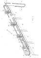
- FIG. 1 1 generally indicated by the reference numeral 10, has a curtain rail 12 to be fastened to a ceiling or wall, made of light metal, in particular aluminum (see FIG. 2), in which sliding elements 14, 14b are guided in a longitudinally displaceable manner.
- sliding elements 14, 14a, 14b are shown; as a rule, however, significantly more sliding elements 14 are provided.
- each sliding element 14 On the vertical pivot axis 16 of each sliding element 14 (see FIGS. 2 and 3), a curtain strip is fastened in the usual manner, for example described in DE-PS 2 792 491. In the embodiment according to FIG. 1, four curtain strips 18 are provided corresponding to the number of sliding elements 14.
- the curtain strips 18 can thus be pivoted into any, continuously adjustable angular positions, as is indicated in FIG. 4 by the partial circle arrow.
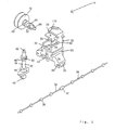
- the curtain rail 12 has a rectangular cross-section (see FIG. 2) and is provided on its underside with a longitudinal slot which extends over the entire length of the curtain rail 12.
- the two edges 12a of the hollow profile of the curtain rail 12 which delimit this longitudinal slot serve for the form-fitting but movable fixing of the sliding elements 14 in that these edges 12a into corresponding, groove-shaped, mutually parallel recesses 20 in the side walls of the base body 22 of the sliding elements 14 (see FIG. 3 ) can be inserted.
- the base body 22 has an upper, box-shaped main part 24 above the recesses 20 and under the recesses 20 protruding outwards 26 with a slot-shaped opening 28 which widens into an approximately egg-shaped recess 30.
- a likewise approximately egg-shaped connecting element 32 of a ball chain 34 is received, which in addition to the egg-shaped connecting elements 32 also has balls 36 at certain intervals.
- the cord 38 of the ball chain 34 in addition to the connecting element 32 is guided through the slots 28, so that each sliding element 14 is firmly connected to the ball chain 34.
- the upper main part 24 of the base body 20 is approximately box-shaped with two open sides; in the bottom of this box a cylindrical receptacle 40 is formed for the cylindrical middle part 42 of the pivot axis 16; this central part 42 is inserted into the cylindrical receptacle 40 via a longitudinal slot 44 (see FIG. 2) and held there in a form-fitting manner, but rotatable about a vertical axis.
- the pivot axis 16 has thickenings 46 above and below the cylindrical middle part 42, so that the pivot axis 42 has somewhat perpendicular play, but cannot fall out of the cylindrical recesses 44 upwards or downwards.
- the element 48 for fastening the curtain strips 18 is located at the lower end of the pivot axis 16, while a partial gearwheel 50 with beveled teeth is formed above the upper thickening 46.
- the gear wheel 50, the cylindrical middle part 42, the thickenings 46, 48 and the fastening element 48 are produced in one piece, in particular injection molded from a suitable plastic, such as polyamide.
- the upper end of the pivot axis 16 is provided with a likewise integrally formed pin 52, which is rotatably received in a corresponding bore 54 in the upper side of the base body 22 and is thereby guided.
- a side wall of the base body 22 has a slot 56 which is open on one side and ends in a widening 58 with a circular cross section.
- a recess 60 with a circular cross section, which is also open on one side (FIG. 3).
- the axis 62 is thus inserted through the slot 56 and then held by means of the pin 66 in the widening 58 and the circumferential groove 68 in the recess 60 by the two side walls of the main part 24 in a form-fitting and rotatable manner.
- a pulley 70 with a groove-shaped depression with bevelled side walls sits on the axis 62, as can be seen from FIG. 2.
- Each sliding element 14 from the three individual parts explained is mounted in the curtain rail 12 in the manner shown in FIG. 2, so that the base body 22 can be moved along the curtain rail 12 and the pulley 70 can be rotated.
- the axis 62 also rotates with the pulley 70; since the worm gear 64 is in engagement with the gear of the pivot axis 16, the pivot axis 16 is rotated accordingly.
- a cord 72 is made of a resistant, textile material, in particular a plastic, the diameter of which is slightly larger than the cross-sectional area of the groove of the pulley 70, so that the cord 72 is slightly over the pulley 70 protrudes and rests against the web 12a of the curtain rail 12, as can be seen in FIG. 2. This ensures reliable non-positive engagement between the cord 72 and the pulley 70.
- the cord 72 is designed as an endless cord and runs from its actuation area 75, over a horizontal roller 80, over the pulleys 70 of all sliding elements 14 in the curtain rail 12, then around a deflection roller 78 with a vertical axis through the curtain rail 12 back via a horizontal roller 76 back to the actuation area 74.
- the returning part of the cord 72 is indicated at 82 in FIGS. 1 and 4.
- the pulleys 70 can no longer rotate; the frictional connection between the pulleys 70 and the cord 72 now causes the pulleys 70 and thus also the sliding elements 14, 14b to be carried along, that is to say shifted to the right as shown in FIG. 1, until the three left movable sliding elements 14, 14b rest on the right, staéeary sliding element 14a. So that the "strip package" is on the right side of the strip curtain 10, the individual curtain strips 18 are arranged in their end position, at an angle of about 20 ° to the cord 72, and thus take up little space, so that for example otherwise hidden by the strip curtain 10 windows (not shown) is exposed.
- the two middle sliding elements 14 are taken along either by the left, outer sliding element 14b when moving to the right or by the ball chain 34 when moving to the left, so that even when the frictional or frictional connection decreases reliable displacement of these sliding elements 14 is ensured between the pulley 70 of these sliding elements 14 and the cord 72.
- a “precursor” 90 (see FIGS. 1 and 4) is provided, which is formed by an elongated strip made of a resistant plastic.
- This precursor 90 extends along the line 72 around the deflection roller 78 and is fixedly attached to the line 72 at one end with the sliding element 14b and at the other end by means of a connecting element 92 (see FIGS. 1 and 4).
- the strip-shaped precursor 90 has a longitudinal slot 93, in which the connecting element 92 is guided in a movable but non-detachable manner.
- the precursor 90 serves, the connecting element 92 of which is carried along by the cord 72 until it reaches the end of the slot 93 of the precursor 90 and thereby taking the precursor 90 with it, which in turn takes the sliding element 14b firmly connected to the precursor 90 into the open position of the strip curtain 10.
- the connecting element 92 is in contact with the left sliding element 14b.
- the curtain strips 18 are brought out of the package position on the right-hand side into the position shown in FIG. 1 by pulling on the actuation area 74.
- the connecting element 92 with the cord 72 moves away from the sliding element 14b to the end of the slot 93 in the precursor 90.
- the actuating region 74 is pulled further, the sliding elements 14b and 14 move into the end position as shown in FIG. 1.
- FIG. 4a, 4b, 4c show three different layers of the connecting element 92, namely the one end position of the connecting element 92 at one end of the precursor 90 (FIG. 4a), an intermediate layer of the connecting element 92 when the strips are pivoted and thus opened (4b) and the other end position of the connecting element 92 in contact with the sliding element 14b. If the actuation area 75 is pulled further from the position according to FIG. 4c, the sliding elements 14b and 14 shift into the open position (package position).
- additional flanges 12b of the curtain rail 12 are used for fastening end pieces (not shown) which are pushed onto the ends of the curtain rail 12 and which support the rollers 76, 80 and 78, and for the assembly of the entire system the ceiling.
- a cord or string made of a resistant, textile material is used as the drive element, namely the cord 72 with the actuation areas 74, 75.
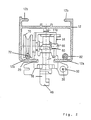
- such an endless cord or plastic string 72 can be guided around a second pulley 100, to which a crank 102 is fastened, such as is also used for opening and closing roller shutters, that is, a rod with a crank-like one Handle (see Fig. 5).
- the pulley 100 By rotating the drive crank 102, the pulley 100 can be rotated and thus the endless cord 72 can be moved.
- FIG. 6 shows a third variant of the drive, in which the endless cord or plastic string 72 also extends around the pulley 100.
- a schematically indicated bevel gear 104 acts on this pulley 100 and can be rotated by means of an endless ball chain 106. By pulling the endless ball chain 106, the bevel gear 104 rotates and takes the pulley 100 with it, so that the endless cord or plastic string 72 is shifted accordingly.
- the two drive means according to FIGS. 5 and 6 generate high drive forces as may be required because of the high friction of this strip curtain; this friction is due to the strong clamping effect between the cord, pulley and profile.
- a curved strip-shaped projection 110 is formed at the upper end of the sliding element 14, which bears against the curtain rail 12 under prestress and presses the sliding element 14 downward as shown in FIG. 2, as a result of which the contact pressure the cord 72 in the gap between the pulley 70 and the web 12a of the curtain rail 12 and thus sufficient friction between the pulley 70 and cord 72 is generated.
- the contact of the spring 110 on the curtain rail 12 provides friction, which counteracts the sliding of the sliding elements 14 during the rotation of the strips 18.
Abstract
Description
Die Erfindung betrifft einen Streifenvorhang der im Oberbegriff des Anspruchs 1 angegebenen Gattung.The invention relates to a strip curtain of the type specified in the preamble of claim 1.
Bei einem Streifenvorhang können die einzelnen Vorhangstreifen so wohl um eine vertikale Achse gedreht als auch in einer vertikalen Ebene verschoben werden, um die einzelnen Vorhangstreifen in verschiedene Winkellagen oder als Streifenpaket auf eine Seite des Streifenvorhanges zu bringen.In the case of a strip curtain, the individual curtain strips can be rotated about a vertical axis as well as shifted in a vertical plane in order to bring the individual curtain strips into different angular positions or as a strip package on one side of the strip curtain.
Zu diesem Zweck ist es aus der GB-OS 2 122 675 bekannt, am oberen Ende jedes Streifens eine horizontale Scheibe vorzusehen, die auf einer Endlosschnur aufliegt. Durch den Reibschluß zwischen der Scheibe und der Schnur, der im wesentlichen von dem Gewicht des Streifens und der Scheibe abhängt, wird bei einer Längsverschiebung der Endlosschnur die Scheibe und damit der Streifenvorhang gedreht bzw. in Längsrichtung verschoben.For this purpose it is known from GB-OS 2 122 675 to provide a horizontal disc at the upper end of each strip which rests on an endless cord. Due to the frictional connection between the disc and the cord, which essentially depends on the weight of the strip and the disc, the disc and thus the strip curtain is rotated or shifted in the longitudinal direction when the endless cord is displaced longitudinally.
Nachteilig bei dieser Lösung ist die relativ große Fläche der Scheiben, die einen Durchmesser von etwa 24 mm haben, so daß sich ein großes Streifenpaket ergibt; es wird jedoch angestrebt, die Streifen sehr nahe beieinander anzuordnen und dadurch beispielsweise die gesamte Fensterfläche freizugeben, was bei der Verwendung solcher Scheiben nicht möglich ist. Weiterhin ist bei diesem bekannten Streifenvorhang keine Untersetzung vorgesehen, so daß sich jede Dehnung der Schnur auch auf die Streifenstellung auswirkt. Und schließlich ist der Reibschluß zwischen der Endlosschnur und der Scheibe nur bei langsamer Bedienung der Endlosschnur ausreichend, weil die Trägheit der Scheiben der Drehbewegung entgegenwirkt. Eine Erhöhung oder insbesondere definierte Einstellung des Reibschlusses ist nicht vorgesehen.A disadvantage of this solution is the relatively large area of the disks, which have a diameter of about 24 mm, so that there is a large strip package; however, the aim is to arrange the strips very close to one another and thereby, for example, to expose the entire window area, which is not possible when using such panes. Furthermore, no reduction is provided in this known strip curtain, so that every stretch of the cord also affects the strip position. And finally, the frictional connection between the endless cord and the disc is only sufficient when the endless cord is operated slowly, because the inertia of the discs counteracts the rotational movement. An increase or, in particular, a defined setting of the frictional engagement is not provided.
Weiterhin geht aus der AT-PS 200 315 eine Lamellenverstelleinrich tung an Jalousien hervor, deren Mitnehmerscheiben als Riemenscheiben ausgebildet sind; in den Umfangsnuten der Riemenscheiben ist eine Endlosschnur eingelegt, die eine Doppelschlaufe bildet. Dadurch entsteht ein aufhebbarer Reibschluß zwischen der Riemenscheibe und der Endlosschnur.Furthermore, from the AT-PS 200 315 a Lamellenverstelleinrich device on blinds emerges, the drive pulleys are designed as pulleys; an endless cord is inserted in the circumferential grooves of the pulleys, which forms a double loop. This creates a reversible frictional connection between the pulley and the endless cord.
Weiterhin ist aus der DE-PS 27 29 941 ein Streifenvorhang mit einem flexiblen, nicht dehnbaren, an beiden Enden der Vorhangschiene über Umlenkrollen geführten Antriebsband bekannt, bei dem ein Trum in der inneren und das rücklaufende Trum in der äußeren von jeweils zwei beidseitig der Vorhangebene in der Vorhangschiene entlang dieser verlaufenden Bandführungen verläuft. Das innere Trum kämmt mit Zahnrädern, die jeweils über eine Rutschkupplung mit den Schwenkachsen der einzelnen Vorhangstreifen verbunden sind.Furthermore, from DE-PS 27 29 941 a strip curtain with a flexible, non-stretchable drive belt guided at both ends of the curtain rail via deflection rollers is known, in which one strand in the inner and the returning strand in the outer of two on both sides of the curtain plane runs in the curtain track along these running tape guides. The inner strand meshes with gear wheels, each of which is connected to the swivel axes of the individual curtain strips via a slip clutch.
Dieser Streifenvorhang eignet sich insbesondere für große Anlagen, bei denen die Vorhangschienen auch gebogen sein können. An die mechanischen Eigenschaften und insbesondere die Fertigungsgenauigkeit des Antriebsbandes werden jedoch sehr hohe Anforderungen gestellt, da schon eine geringe Flexibilität, aber auch geringfügige Toleranzschwankungen zwischen Zahnrad und Antriebsband, zu einer ungleichmäßigen Verschwenkung der einzelnen Vorhangstreifen führen können.This strip curtain is particularly suitable for large systems in which the curtain rails can also be curved. However, very high demands are placed on the mechanical properties and in particular the manufacturing accuracy of the drive belt posed, since even a little flexibility, but also slight tolerance fluctuations between gear and drive belt, can lead to an uneven pivoting of the individual curtain strips.
Deshalb ist aus der EU-PS 81 465 eine Weiterentwicklung eines solchen Streifenvorhangs bekannt, bei der das Antriebsband durch eine Kugelkette ersetzt wird; das Zahnrad ist über einen Schneckentrieb mit der Schwenkachse verbunden, wobei sich die Rutschkupplung zwischen dem Zahnrad und dem Schneckentrieb befindet.Therefore, a further development of such a strip curtain is known from EU-PS 81 465, in which the drive belt is replaced by a ball chain; the gear is connected to the swivel axis via a worm gear, the slip clutch being located between the gear and the worm gear.
Der Vorteil dieser Ausführungsform liegt darin, daß die Gleitelemente um Kurven geführt und in jeder Lage verdreht werden können. Auch die Montage des Streifenvorhanges an Dachschrägen ist ohne weiteres möglich.The advantage of this embodiment is that the sliding elements can be guided around curves and rotated in any position. The strip curtain can also be easily installed on sloping ceilings.
Nachteilig ist jedoch der relativ komplizierte Aufbau der einzelnen Gleitelemente mit Rutschkupplung, Schneckentrieb und gegebenenfalls zusätzlicher Friktionsbremse, der fertigungstechnisch sehr aufwendig ist. Dabei ist auch zu berücksichtigen, daß die Einzelteile mit hoher Präzision gefertigt werden müssen.A disadvantage, however, is the relatively complicated structure of the individual sliding elements with a slip clutch, worm drive and, if appropriate, an additional friction brake, which is very complex in terms of production technology. It should also be borne in mind that the individual parts must be manufactured with high precision.
Der Zusammenbau der Einzelteile zu dem fertigen Gleitelement ist ebenfalls sehr kompliziert, so daß hierzu nur entsprechend geschulte Fachkräfte eingesetzt werden können.The assembly of the individual parts to the finished sliding element is also very complicated, so that only appropriately trained specialists can be used for this.
Der Erfindung liegt deshalb die Aufgabe zugrunde, einen Streifenvorhang der angegebenen Gattung zu schaffen, bei dem das Gleitelement nur wenige Einzelteile hat und sich einfach zusammenbauen läßt.The invention is therefore based on the object to provide a strip curtain of the type specified, in which the sliding element has only a few individual parts and can be easily assembled.
Dies wird erfindungsgemäß durch die im kennzeichnenden Teil des Anspruchs 1 angegebenen Merkmale erreicht.This is achieved according to the invention by the features specified in the characterizing part of claim 1.
Zweckmäßige Ausführungsformen werden durch die Merkmale der Unteransprüche definiert.Expedient embodiments are defined by the features of the subclaims.
Die mit der Erfindung erzielten Vorteile beruhen auf dem Ersatz der Rutschkupplung durch den lösbaren kraftschlüssigen Eingriff zwischen einer Schnur und einer Riemenscheibe, die mit dem Schneckentrieb kämmt und nach einer bevorzugten Ausführungsform einstückig mit dem Schneckentrieb und koaxial zu diesem ausgebildet, beispielsweise gleichzeitig spritzgegossen worden ist.The advantages achieved by the invention are based on the replacement of the slip clutch by the releasable non-positive engagement between a cord and a pulley, which meshes with the worm drive and, according to a preferred embodiment, is formed in one piece with the worm drive and coaxially with it, for example, it has been injection molded simultaneously.
Die bisher übliche, konstruktiv aufwendige Rutschkupplung ist nicht mehr erforderlich, da die Schnur zunächst die Riemenscheiben und damit die Schwenkachsen dreht, wodurch die Vorhangstreifen synchron zueinander um ihre vertikalen Achsen gedreht werden. In ihren beiden Endlagen laufen die Schwenkachsen gegen Anschläge, so daß keine weitere Drehung der Schwenkachsen und damit der Riemenscheiben mehr möglich ist. Nun werden die Riemenscheiben und damit auch die Gleitelemente von der laufenden Schnur mitgenommen, so daß sie sich als "Streifenpaket" auf einer Seite des Streifenvorhangs sammeln können.The previously customary, structurally complex slip clutch is no longer required, since the cord first rotates the pulleys and thus the swivel axes, as a result of which the curtain strips are rotated synchronously with one another about their vertical axes. In their two end positions, the swivel axes run against stops, so that no further rotation of the swivel axes and thus the pulleys is possible. Now the pulleys and thus also the sliding elements are taken along by the running cord, so that they can collect as a "strip package" on one side of the strip curtain.
Dabei laufen die einzelnen Gleitelemente aufeinander auf und werden dadurch angehalten, so daß nun die Schnur über die Riemenscheibe "rutscht", ohne daß eine zusätzliche Rutschkupplung vorgesehen werden muß.The individual sliding elements run onto one another and are thereby stopped, so that the cord now "slips" over the pulley without an additional slip clutch having to be provided.
Das als Massenartikel anzusehende Gleitelement besteht also im Vergleich mit den bisher üblichen Ausführungsformen aus weniger Einzelteilen, so daß es sich preisgünstig herstellen und auch zusammenbauen läßt. Auch der Zusammenbau wird einfacher, so daß die Fertigung nun von Hilfskräften übernommen werden kann, die keine spezielle Ausbildung haben.The sliding element, which is to be regarded as a mass article, therefore consists of fewer individual parts in comparison with the previously customary embodiments, so that it can be inexpensively manufactured and also assembled. The assembly is also easier, so that the production can now be carried out by assistants who have no special training.
Bei zweckmäßiger Ausgestaltung besteht ein Gleitelement nur noch aus drei Einzelteilen, nämlich einem Grundkörper, in dem die Schwenkachse mit dem Gegenelement einerseits und der Schneckentrieb mit der Riemenscheibe andererseits befestigt werden.In an expedient embodiment, a sliding element only consists of three individual parts, namely a base body, in which the pivot axis with the counter element on the one hand and the worm drive with the pulley on the other hand are fastened.
Der Eingriff der Schwenkachse und der Riemenscheibe mit dem Schnekkentrieb in dem Grundkörper erfolgt kraft- und/oder formschlüssig in entsprechenden Ausnehmungen, so daß keine zusätzlichen Befestigungsmittel erforderlich sind.The engagement of the swivel axis and the pulley with the worm gear in the base body is non-positive and / or positive in corresponding recesses, so that no additional fasteners are required.
Die Riemenscheibe weist eine etwa u-förmige Rinne mit abgeschrägten Wänden für die Aufnahme der Schnur auf; sie ist so angeordnet, daß sich die Schnur zwischen einer Wand der Vorhangschiene und der Riemenscheibe befindet. Auf diese Weise wird ausgeschlossen, daß sich beim Betrieb die Schnur von der Riemenscheibe lösen kann. Außerdem läßt sich so noch ein zusätzlicher Anpreßdruck erzeugen.The pulley has an approximately U-shaped groove with bevelled walls for receiving the cord; it is arranged so that the cord is between a wall of the curtain rail and the pulley. In this way it is excluded that the cord can come loose from the pulley during operation. In addition, an additional contact pressure can be generated.
Die Schnur wird aus einem textilen Material, zweckmäßigerweise aus einem verschleißfesten Kunststoff hergestellt und läuft praktisch geräuschlos zwischen Vorhangschiene und Riemenscheibe, so daß sich im Vergleich mit der bisher üblichen Kugelkette, aber auch dem flexiblen Antriebsband, eine wesentliche Verringerung des Lärmpegels ergibt.The cord is made of a textile material, expediently made of a wear-resistant plastic and runs practically noiselessly between the curtain rail and the pulley, so that there is a significant reduction in the noise level in comparison with the ball chain that was previously common, but also with the flexible drive belt.
Als Abstandsbegrenzungsorgan kann eine Schnur, aber auch eine Kugelkette dienen, die fest mit den einzelnen Gleitelementen verbunden ist und keine Antriebsfunktion erfüllt, sondern nur dafür sorgt, daß bei der Verschiebung der einzelnen Gleitelemente diese in vorgegebenen Abständen zueinander fixiert werden.A cord, but also a ball chain, which is firmly connected to the individual sliding elements and does not perform a drive function, can only serve as a distance limiting member, but only ensures that when the individual sliding elements are displaced, they are fixed at predetermined distances from one another.
Dieser Streifenvorhang läßt sich auch um extreme Krümmungen führen, da das eigentliche Antriebselement, nämlich die Schnur, beliebig verformt werden kann. Es muß nur dafür gesorgt werden, daß die Vorhangschiene, die die Führungsfunktion für die Gleitelemente und die Schnur übernimmt, mit der entsprechenden Form hergestellt wird.This strip curtain can also be led around extreme curvatures, since the actual drive element, namely the cord, can be deformed as desired. It is only necessary to ensure that the curtain rail, which takes over the guiding function for the sliding elements and the cord, is manufactured with the appropriate shape.
Auch die Form der Vorhangschiene vereinfacht sich im Vergleich mit den herkömmlichen Ausführungsformen, da einfache, leichte Aluminiumprofile ohne aufwendige und fertigungstechnisch komplizierte Gestaltung eingesetzt werden können; solche einfachen Aluminiumprofile lassen sich problemlos den üblichen Krümmungen anpassen.The shape of the curtain rail is also simplified in comparison with the conventional embodiments, since simple, light aluminum profiles can be used without complex and production-technically complicated design; Such simple aluminum profiles can be easily adapted to the usual curvatures.
Im Unterschied zu vielen herkömmlichen Ausführungsformen sind die Gleitelemente auch seitenunabhängig, d. h., es gibt nur noch eine Ausführungsform der Gleitelemente, mit der je nach Montage die einzelnen Vorhangstreifen auf die linke oder auf die rechte Seite des Streifenvorhanges verschoben werden können. Bei den bisher üblichen Ausführungsformen mußte jeweils ein entsprechendes Gleitelement verwendet werden, wenn der Streifenvorhang mit linker oder rechter Streifenpaketanordnung benutzt werden sollte.In contrast to many conventional embodiments, the sliding elements are also independent of the side, i. that is, there is only one embodiment of the sliding elements with which, depending on the assembly, the individual curtain strips can be moved to the left or to the right side of the strip curtain. In the previously customary embodiments, a corresponding sliding element had to be used in each case if the strip curtain with left or right strip packet arrangement was to be used.
Auch die Anpassung der Abstände zwischen den einzelnen Streifen bereitet keine Probleme, da hierzu unabhängig von dem eigentlichen Antriebselement, nämlich der beliebig verformbaren Schnur, nur noch das Abstandsbegrenzungsorgan, beispielsweise eine Kugelkette, in den gewünschten Abständen mit den einzelnen Gleitelementen verbunden werden muß.Also, the adjustment of the distances between the individual strips presents no problems, since for this purpose, only the distance limiting member, for example a ball chain, has to be connected to the individual sliding elements at the desired intervals, regardless of the actual drive element, namely the cord which can be deformed as desired.
Beim normalen Betrieb werden die Riemenscheiben gedreht, wenn man an der Antriebsschnur zieht, wodurch die Schwenkachsen der Gleitelemente und damit die Vorhangstreifen in die entsprechende Winkellage gebracht werden. Nach Erreichen der beiden Endlagen der Schwenkachse dreht sich jedoch die Riemenscheibe nicht mehr, so daß nun der Reibungseingriff wirksam wird und die Gleitelemente von der Schnur mitgenommen werden, bis sie die gewünschte Endlage erreichen.In normal operation, the pulleys are turned when you pull the drive cord, which brings the swivel axes of the sliding elements and thus the curtain strips into the corresponding angular position. After reaching the two end positions of the swivel axis, however, the pulley no longer rotates, so that the frictional engagement now takes effect and the sliding elements are carried along by the cord until they reach the desired end position.
Dieser Ablauf gilt für alle Gleitelemente eines Vorhangs mit Ausnahme der beiden äußeren, von denen ein Gleitelement fest an der Vorhangschiene angebracht ist, und zwar auf der Seite, auf der beim normalen Betrieb das Streifenpaket angeordnet werden muß. Auch dieses Gleitelement weist eine Riemenscheibe auf, damit die Schnur die Schwenkachse dieses Gleitelementes entsprechend den anderen Schwenkachsen verstellen kann. Eine Verschiebung dieses Gleitelementes ist jedoch nicht möglich, da es fest mit der Vorhangschiene verbunden, z. B. verschraubt ist.This procedure applies to all sliding elements of a curtain with the exception of the two outer ones, of which one sliding element is fixedly attached to the curtain rail, on the side on which the strip package must be arranged during normal operation. This sliding element also has a pulley so that the cord can adjust the pivot axis of this sliding element in accordance with the other pivot axes. A displacement of this sliding element is not possible, however, since it is firmly connected to the curtain rail, e.g. B. is screwed.
Das Gleitelement am anderen Ende des Streifenvorhangs weist ebenfalls eine Riemenscheibe auf, um seine Schwenkachse synchrom mit den Schwenkachsen der anderen Gleitelemente zu drehen und nach Erreichen der Endlagen dieser Drehbewegung dieses Gleitelement in der Vorhangschiene in seine äußere Endlage zu verschieben.The sliding element at the other end of the strip curtain also has a pulley in order to rotate its pivot axis in synchronism with the pivot axes of the other sliding elements and, after reaching the end positions of this rotary movement, this sliding element in the curtain rail into its outer To move the end position.
Damit beim Ziehen an der Schnur das Gleitelement am Ende der Vorhangschiene sicher und zuverlässig mitgenommen wird, kann ein zusätzlicher "Vorläufer" eingesetzt werden, nämlich ein Streifen aus einem flexiblen, widerstandsfähigen Material, der mit der Schnur und dem letzten Gleitelement verbunden ist. Die Verbindung zwischen Vorläufer und Schnur dient als Mitnehmer, der beim Ziehen an der Schnur in Anlage an das letzte Gleitelement kommt und dieses zusammen mit der Schnur weitertransportiert.So that the sliding element at the end of the curtain rail is taken safely and reliably when pulling on the cord, an additional "precursor" can be used, namely a strip made of a flexible, resistant material, which is connected to the cord and the last sliding element. The connection between the forerunner and the cord serves as a driver that comes into contact with the last sliding element when the cord is pulled and transports it along with the cord.
Die Erfindung wird im folgenden anhand eines Ausführungsbeispiels unter Bezugnahme auf die beiliegenden schematischen Zeichnungen näher erläutert. Es zeigen
- Fig. 1 eine perspektivische Ansicht des Streifenvorhangs mit vier Gleitelementen, wobei jedoch die zur Führung der Gleitelemente dienende Vorhangschiene nicht dargestellt ist,
- Fig. 2 einen senkrechten Schnitt durch die Vorhangschiene, ein Gleitelement und die Schnur,
- Fig. 3 eine Darstellung der Einzelteile eines Gleitelementes, nämlich des Grundkörpers, der Schwenkachse, des Schneckentriebes mit der Riemenscheibe und der Kugelkette,
- Fig. 4 a, b und c eine perspektivische Ansicht des Gleitelementes an einem Ende des Streifenvorhangs mit verschiedenen Lagen des zugehörigen Vorläufers,
- Fig. 5 eine perspektivische Ansicht des Randbereiches eines Streifenvorhanges mit Kurbelantrieb, und
- Fig. 6 eine perspektivische Ansicht des Bandbereiches eines Streifenvorhanges mit Kugelkettenantrieb.
- 1 is a perspective view of the strip curtain with four sliding elements, but the curtain rail used to guide the sliding elements is not shown,
- 2 shows a vertical section through the curtain rail, a sliding element and the cord,
- 3 shows the individual parts of a sliding element, namely the base body, the swivel axis, the worm drive with the belt pulley and the ball chain,
- 4 a, b and c is a perspective view of the sliding element at one end of the strip curtain with different layers of the associated precursor,
- 5 is a perspective view of the edge region of a strip curtain with crank drive, and
- Fig. 6 is a perspective view of the band area of a strip curtain with ball chain drive.
Der aus Fig. 1 ersichtliche, allgemein durch das Bezugszeichen 10 angedeutete Streifenvorhang weist eine an einer Decke oder Wand zu befestigende Vorhangschiene 12 aus Leichtmetall, insbesondere Aluminium (siehe Fig. 2) auf, in der Gleitelemente 14, 14b längs verschiebbar geführt sind. Bei dem Streifenvorhang 10 nach Fig. 1 sind vier Gleitelemente 14, 14a, 14b dargestellt; in aller Regel sind jedoch wesentlich mehr Gleitelemente 14 vorgesehen.1, generally indicated by the
An der vertikalen Schwenkachse 16 jedes Gleitelementes 14 (siehe Fig. 2 und 3) ist ein Vorhangstreifen auf die übliche, beispielsweise in der DE-PS 2 792 491 beschriebene Weise befestigt. Bei der Ausführungsform nach Fig. 1 sind entsprechend der Zahl der Gleitelemente 14 vier Vorhangstreifen 18 vorgesehen.On the
Durch Drehen der vertikalen Schwenkachsen 16 können also die Vorhangstreifen 18 in beliebige, stufenlos verstellbare Winkellagen geschwenkt werden, wie in Fig. 4 durch den Teilkreispfeil angedeutet ist.By rotating the vertical pivot axes 16, the curtain strips 18 can thus be pivoted into any, continuously adjustable angular positions, as is indicated in FIG. 4 by the partial circle arrow.
Die Vorhangschiene 12 hat im Querschnitt Rechteckform (siehe Fig. 2) und ist an ihrer Unterseite mit einem Längsschlitz versehen, der sich über die ganze Länge der Vorhangschiene 12 erstreckt.The
Die diesen Längsschlitz begrenzenden beiden Kanten 12a des Hohlprofils der Vorhangschiene 12 dienen zur formschlüssigen, jedoch beweglichen Fixierung der Gleitelemente 14, indem diese Kanten 12a in entsprechende, rinnenförmige, zueinander parallele Aussparungen 20 in den Seitenwänden der Grundkörper 22 der Gleitelemente 14 (siehe Fig. 3) eingeschoben werden.The two
Der Grundkörper 22 weist einen oberen, kastenförmigen Hauptteil 24 über den Aussparungen 20 sowie unter den Aussparungen 20 schräg nach außen ragende Vorsprünge 26 mit einer schlitzförmigen Öffnung 28 auf, die sich zu einer etwa eiförmigen Aussparung 30 erweitert. In dieser eiförmigen Aussparung 30 wird ein ebenfalls etwa eiförmiges Verbindungselement 32 einer Kugelkette 34 aufgenommen, die neben den eiförmigen Verbindungselementen 32 in bestimmten Abständen noch Kugeln 36 aufweist. Die Schnur 38 der Kugelkette 34 neben dem Verbindungselement 32 wird durch die Schlitze 28 geführt, so daß jedes Gleitelement 14 fest mit der Kugelkette 34 verbunden ist.The
Der obere Hauptteil 24 des Grundkörpers 20 hat etwa Kastenform mit zwei offenen Seiten; im Boden dieses Kastens ist eine zylindrische Aufnahme 40 für den zylindrischen Mittelteil 42 der Schwenkachse 16 ausgebildet; dieser Mittelteil 42 wird über einen Längsschlitz 44 in die zylindrische Aufnahme 40 eingeführt (siehe Fig. 2) und dort formschlüssig, jedoch um eine lotrechte Achse drehbar, gehalten.The upper
Die Schwenkachse 16 weist über dem zylindrischen Mittelteil 42 oben und unten Verdickungen 46 auf, so daß die Schwenkachse 42 zwar etwas lotrechtes Spiel hat, jedoch nicht nach oben oder unten aus den zylindrischen Ausnehmungen 44 herausfallen kann.The
Am unteren Ende der Schwenkachse 16 befindet sich das Element 48 zur Befestigung der Vorhangsstreifen 18, während über der oberen Verdickung 46 ein Teil-Zahnrad 50 mit abgeschrägten Zähnen ausgebildet ist. Das Zahnrad 50, der zylindrische Mittelteil 42, die Verdickungen 46, 48 und das Befestigungselement 48 werden einstückig hergestellt, insbesondere aus einem geeigneten Kunststoff, wie beispielsweise Polyamid, gespritzt.The
Das obere Ende der Schwenkachse 16 ist mit einem ebenfalls einstückig ausgebildeten Stift 52 versehen, der in einer entsprechenden Bohrung 54 in der Oberseite des Grundkörpers 22 drehbar aufgenommen und dadurch geführt ist.The upper end of the
Eine Seitenwand des Grundkörpers 22 weist einen an einer Seite offenen Schlitz 56 auf, der in einer Verbreiterung 58 mit kreisförmigem Querschnitt endet. In der gegenüberliegenden Seitenwand des Grundkörpers 22 befindet sich eine Aussparung 60 mit kreisförmigem Querschnitt, die ebenfalls an einer Seite offen ist (Fig. 3).A side wall of the
Die beiden Aussparungen 56, 58 einerseits und 60 andererseits dienen zur Aufnahme der Achse 62 eines Schneckentriebes 64, die an einem Ende mit einem in die Verbreiterung 58 passenden Stift 66 und am anderen Ende mit einer ringförmigen, umlaufenden Aussparung 68 versehen ist, deren Breite etwas größer als die Breite einer Seitenwand des Hauptteils 24 ist. Die Achse 62 wird also über den Schlitz 56 eingeführt und dann mittel des Stiftes 66 in der Verbreiterung 58 sowie der umlaufenden Rille 68 in der Aussparung 60 von den beiden Seitenwände des Hauptteils 24 formschlüssig und drehbar gehalten.The two
Auf der Achse 62 sitzt eine Riemenscheibe 70 mit einer rillenförmigen Vertiefung mit abgeschrägten Seitenwänden, wie man aus Fig. 2 erkennt.A
Jedes Gleitelement 14 aus den drei erläuterten Einzelteilen wird auf die aus Fig. 2 ersichtliche Weise in der Vorhangschiene 12 montiert, so daß der Grundkörper 22 längs der Vorhangschiene 12 verschoben und die Riemenscheibe 70 gedreht werden kann. Mit der Riemenscheibe 70 dreht sich auch die Achse 62; da sich der Schneckentrieb 64 im Eingriff mit dem Zahnrad der Schwenkachse 16 befindet, wird die Schwenkachse 16 entsprechend gedreht.Each sliding
Wie man aus Fig. 3 erkennt, ist an der Schwenkachse 16 nur ein "Halbzahnrad" 50 vorgesehen, wodurch sich eine entsprechende Beschränkung der Schwenkbewegung der Schwenkachse 16 ergibt. Für die normalen Zwecke reicht eine Schwenkbewegung der Schwenkachse 16 über einen Winkel von etwas weniger als 180° aus, wie es durch die dargestellte Form des Halbzahnrades 50 in Verbindung mit dem Schneckentrieb 64 erreicht wird.As can be seen from FIG. 3, only a "half gear" 50 is provided on the
Als Antriebselement für die Drehung der Riemenscheibe 70 und die Verschiebung der Gleitelemente 14 dient eine Schnur 72 aus einem widerstandsfähigen, textilen Material, insbesondere einem Kunststoff, deren Durchmesser etwas größer als die Querschnittsfläche der Rinne der Riemenscheibe 70 ist, so daß die Schnur 72 etwas über die Riemenscheibe 70 hinaus vorsteht und an dem Steg 12a der Vorhangschiene 12 anliegt, wie man in Fig. 2 erkennt. Dadurch wird ein zuverlässiger kraftschlüssiger Eingriff zwischen der Schnur 72 und der Riemenscheibe 70 gewährleistet.As a drive element for the rotation of the
Wie man aus Fig. 1 erkennt, ist die Schnur 72 als Endlosschnur ausgebildet und verläuft von ihrem Betätigungsbereich 75, über eine waagerechte Rolle 80, über die Riemenscheiben 70 aller Gleitelemente 14 in der Vorhangschiene 12, dann um eine Umlenkrolle 78 mit lotrechter Achse durch die Vorhangschiene 12 zurück über eine waagerechte Rolle 76 wieder zu dem Betätigungsbereich 74. Der zurücklaufende Teil der Schnur 72 ist in Fig. 1 und 4 bei 82 angedeutet.As can be seen from FIG. 1, the
Zieht man in der aus Fig. 1 ersichtlichen Lage des Streifenvorhangs 10 an dem Betätigungsbereich 75, so wird der Teil 72 der Schnur gemäß der Darstellung in Fig. 1 nach rechts verschoben; durch den kraftschlüssigen Eingriff zwischen der Schnur 72 und der Riemenscheibe 70, die durch den Steg 12a unterstützt wird, drehen sich bei dieser Verschiebung der Schnur 72 die Riemenscheiben 70, so daß auch die Schwenkachsen 16 gedreht und damit die Vorhangstreifen 18 verschwenkt werden.If, in the position of the
Ist beim weiteren Ziehen an der Schnur 72 die entsprechende Endlage der Schwenkbewegung erreicht, so können sich die Riemenscheiben 70 nicht mehr mitdrehen; der Kraftschluß zwischen den Riemenscheiben 70 und der Schnur 72 bewirkt nun, daß die Riemenscheiben 70 und damit auch die Gleitelemente 14, 14b mitgenommen, also gemäß der Darstellung in Fig. 1 nach rechts verschoben werden, bis die drei linken, beweglichen Gleitelemente 14, 14b an dem rechten, stazionären Gleitelement 14a anliegen. Damit befindet sich das "Streifenpaket" auf der rechten Seite des Streifenvorhangs 10, wobei die einzelnen Vorhangstreifen 18 in ihrer Endlage, in einem Winkel von ca. 20° zur Schnur 72, angeordnet sind, und damit nur wenig Raum einnehmen, so daß beispielsweise das sonst durch den Streifenvorhang 10 verdeckte Fenster (nicht dargestellt) frei liegt.If the corresponding end position of the pivoting movement is reached when the
Zieht man nun an dem Betätigungsbereich 74 der Schnur, so wird der Teil 82 der Schnur gemäß der Darstellung in Fig. 1 nach rechts verschoben; dadurch werden zunächst wieder die Riemenscheiben 70 gedreht, so daß die Schwenkachsen 16 und damit die Vorhangstreifen 18 in die andere Endlage gebracht werden. Sobald diese Endlage erreicht ist, werden die Gleitelemente 14 von der Schnur 72 wieder mitgenommen und damit aus der "Paketanordnung" in die aus Fig. 1 ersichtliche Endlage gebracht, wobei der Abstand zwischen den einzelnen Gleitelementen 14 durch die Kugelkette 34 vorgegeben wird.If the pulling
Bei dem Streifenvorhang 10 nach Fig. 1 werden die beiden mittleren Gleitelemente 14 entweder durch das linke, äußere Gleitelement 14b bei der Bewegung nach rechts oder durch die Kugelkette 34 bei der Bewegung nach links mitgenommen, so daß selbst bei einem Nachlassen des Kraft- oder Reibschlusses zwischen der Riemenscheibe 70 dieser Gleitelemente 14 und der Schnur 72 die zuverlässige Verschiebung dieser Gleitelemente 14 gewährleistet ist.In the
Um auch bei einem Nachlassen des Reibschlusses die gewünschte Bewegung des linken Gleitelementes 14b zu gewährleisten, wird ein "Vorläufer" 90 (siehe die Fig. 1 und 4) vorgesehen, der durch einen langgestreckten Streifen aus einem widerstandsfähigen Kunststoff gebildet wird. Dieser Vorläufer 90 erstreckt sich längs der Schnur 72 um die Umlenkrolle 78 und ist an einem Ende fest mit dem Gleitelement 14b und am anderen Ende mittels eines Verbindungselementes 92 (siehe Fig. 1 und 4) verschiebbar an der Schnur 72 angebracht. Der streifenförmige Vorläufer 90 weist einen Längsschlitz 93 auf, in dem das Verbindungselement 92 beweglich, jedoch unlösbar geführt ist.In order to ensure the desired movement of the left sliding
Beim Öffnen des Streifenvorhangs, um die einzelnen Vorhangstreifen 18, gemäß der Darstellung in Fig 1. auf die rechte Seite zu bringen, wird, wie erläutert, am Betätigungsbereich 75 der Schnur gezogen, so daß bei einwandfreiem Reibschluß zwischen Schnur 72 und Riemenscheiben 70 die Gleitelemente 14, 14b, unterstützt durch die Kugelkette 34, mitgenommen werden. Um auch bei Nachlassen des Reibschlusses diese Verschiebung der Gleitelemente 14, 14b in Anlage an das stationäre Gleitelement 14a zu gewährleisten, dient der Vorläufer 90, dessen Verbindungselement 92 von der Schnur 72 mitgenommen wird, bis es das Ende des Schlitzes 93 des Vorläufers 90 erreicht und dadurch den Vorläufer 90 mitnimmt, wodurch wiederum das fest mit dem Vorläufer 90 verbundene Gleitelement 14b in die geöffnete Lage des Streifenvorhangs 10 mitgenommen wird. Das Verbindungselement 92 befindet sich, wie aus Fig. 1 ersichtlich, in Anlage vor dem linken Gleitelement 14b. Bei der Verschiebung des linken Gleitelementes 14b kommt es in Anlage an die weiter rechts befindlichen Gleitelemente 14, die dann ebenfalls mitgenommen werden, bis sie an dem rechten stationären Gleitelement 14a anliegen.When the strip curtain is opened in order to bring the individual curtain strips 18 to the right side, as shown in FIG 14, 14b, supported by the
Beim Schließen des Streifenvorhanges werden die Vorhangstreifen 18 aus der Paketlage auf der rechten Seite in die aus Fig. 1 ersichtliche Lage gebracht, indem am Betätigungsbereich 74 gezogen wird. Während des Verschwenkens der Vorhangstreifen 18 verschiebt sich das Verbindungselement 92 mit der Schnur 72 vom Gleitelement 14b weg ans Ende des Schlitzes 93 im Vorläufer 90. Bei weiterem Ziehen am Betätigungsbereich 74 verschieben sich die Gleitelemente 14b und 14 in die Endlage gemäß der Darstellung in Fig. 1.When the strip curtain is closed, the curtain strips 18 are brought out of the package position on the right-hand side into the position shown in FIG. 1 by pulling on the
Die Fig. 4a, 4b, 4c zeigen drei verschiedene Lagen des Verbindungselementes 92, und zwar die eine Endlage des Verbindungselementes 92 an einem Ende des Vorläufers 90 (Fig. 4a), eine Zwischenlage des Verbindungselementes 92 bei geschwenkten und damit geöffneten Streifen (4b) und die andere Endlage des Verbindungselementes 92 in Anlage an dem Gleitelement 14b. Bei weiterem Ziehen am Betätigungsbereich 75 aus der Lage nach Fig. 4c verschieben sich die Gleitelemente 14b und 14 in die geöffnete Position (Paketlage).4a, 4b, 4c show three different layers of the connecting
Die aus Fig. 2 ersichtlichen, zusätzlichen Flansche 12b der Vorhangschiene 12 dienen zur Befestigung von Stirnstücken (nicht dargestellt), die auf die Enden der Vorhangschiene 12 aufgeschoben werden und die Rollen 76, 80 bzw. 78 lagern, und der Montage des ganzen Systems an der Decke.2,
Bei der bisher beschriebenen Ausführungsform wird als Antriebselement eine Schnur oder Saite aus einem widerstandsfähigen, textilen Material verwendet, nämlich die Schnur 72 mit den Betätigungsbereichen 74, 75.In the embodiment described so far, a cord or string made of a resistant, textile material is used as the drive element, namely the
Als Alternative hierzu kann eine solche Endlos-Schnur oder Kunststoff-Saite 72 um eine zweite Riemenscheibe 100 geführt werden, an der eine Kurbel 102 befestigt ist, wie sie beispielsweise auch für das Öffnen und Schließen von Rolladen verwendet wird, also eine Stange mit einem kurbelartigen Handgriff (siehe Fig. 5).As an alternative to this, such an endless cord or
Durch Drehen der Antriebskurbel 102 läßt sich die Riemenscheibe 100 drehen und damit die Endlos-Schnur 72 verschieben.By rotating the drive crank 102, the
Fig. 6 zeigt eine dritte Variante des Antriebs, bei der die Endlos-Schnur oder Kunststoff-Saite 72 ebenfalls um die Riemenscheibe 100 verläuft. An dieser Riemenscheibe 100 greift ein schematisch angedeutetes Kegelradgetriebe 104 an, das mittels einer Endlos-Kugelkette 106 gedreht werden kann. Durch Ziehen an der Endlos-Kugelkette 106 dreht sich also das Kegelradgetriebe 104 und nimmt dabei die Riemenscheibe 100 mit, so daß die Endlos-Schnur oder Kunststoff-Saite 72 entsprechend verschoben wird.6 shows a third variant of the drive, in which the endless cord or
Die beiden Antriebsmittel nach den Fig. 5 und 6 erzeugen hohe Antriebskräfte wie sie wegen der hohen Friktion dieses Streifenvorhangs erforderlich werden können; diese Friktion ist auf die starke Klemmwirkung zwischen Schnur, Riemenrad und Profil zurückzuführen.The two drive means according to FIGS. 5 and 6 generate high drive forces as may be required because of the high friction of this strip curtain; this friction is due to the strong clamping effect between the cord, pulley and profile.
Durch die beschriebenen Antriebe wird diese Friktion überwunden und damit die einwandfreie Funktion dieses Streifenvorhanges sichergestellt.This friction is overcome by the drives described and thus the proper functioning of this strip curtain is ensured.
Wie man in den Figuren 2 und 3 erkennt, ist am oberen Ende des Gleitelementes 14 ein gewölbter streifenförmiger Vorsprung 110 ausgebildet, der unter Vorspannung an der Vorhangschiene 12 anliegt und das Gleitelement 14 gemäß der Darstellung in Fig. 2 nach unten drückt, wodurch der Anpreßdruck der Schnur 72 in dem Spalt zwischen der Riemenscheibe 70 und dem Steg 12a der Vorhangschiene 12 und damit eine ausreichende Friktion zwischen Riemenscheibe 70 und Schnur 72 erzeugt wird.As can be seen in FIGS. 2 and 3, a curved strip-shaped
Außerdem liefert die Anlage der Feder 110 an der Vorhangschiene 12 eine Friktion, die dem Verschieben der Gleitelemente 14 während des Drehens der Streifen 18 entgegenwirkt.In addition, the contact of the
Claims (17)
gekennzeichnet durch die folgenden Merkmale:
characterized by the following features:
Applications Claiming Priority (2)
| Application Number | Priority Date | Filing Date | Title |
|---|---|---|---|
| DE19883822727 DE3822727A1 (en) | 1988-07-05 | 1988-07-05 | STRIP CURTAIN |
| DE3822727 | 1988-07-05 |
Publications (1)
| Publication Number | Publication Date |
|---|---|
| EP0349998A1 true EP0349998A1 (en) | 1990-01-10 |
Family
ID=6358002
Family Applications (1)
| Application Number | Title | Priority Date | Filing Date |
|---|---|---|---|
| EP89112229A Withdrawn EP0349998A1 (en) | 1988-07-05 | 1989-07-04 | Vertical blind assembly |
Country Status (2)
| Country | Link |
|---|---|
| EP (1) | EP0349998A1 (en) |
| DE (1) | DE3822727A1 (en) |
Cited By (3)
| Publication number | Priority date | Publication date | Assignee | Title |
|---|---|---|---|---|
| WO1992013165A1 (en) * | 1991-01-24 | 1992-08-06 | K. Bratschi, Silent Gliss | Strip curtain |
| CN103375119A (en) * | 2012-04-17 | 2013-10-30 | 郎海涛 | Vertical blind opening and closing device |
| GB2566432A (en) * | 2017-06-14 | 2019-03-20 | The Bradley Collection Ltd | A Curtain System |
Families Citing this family (1)
| Publication number | Priority date | Publication date | Assignee | Title |
|---|---|---|---|---|
| DE102005001605B3 (en) * | 2005-01-12 | 2006-10-05 | Vkr Holding A/S | Vertical window blind for use with curtain, has pulling chain connected with connecting unit by welded joint, and clip holder forming slot for insertion of bulges or joint, where connecting unit is fastened to pulling carriage |
Citations (4)
| Publication number | Priority date | Publication date | Assignee | Title |
|---|---|---|---|---|
| CH610622A5 (en) * | 1976-05-11 | 1979-04-30 | Thomas Truninger | Vertical slatted blind without positive control |
| DE3000761A1 (en) * | 1979-01-10 | 1980-07-24 | Levolor Lorentzen Inc | Vertical adjustable angle slatted blind operation - involves turning unit for bar and two sets of sprocket wheels |
| GB2122675A (en) * | 1982-06-29 | 1984-01-18 | Pier Luigi Menichetti | Vertical slat blinds |
| EP0120567A2 (en) * | 1983-03-24 | 1984-10-03 | Hunter Douglas Industries B.V. | A clutch for a vertical louvre blind |
Family Cites Families (3)
| Publication number | Priority date | Publication date | Assignee | Title |
|---|---|---|---|---|
| AT200315B (en) * | 1954-12-10 | 1958-10-25 | Schenker Storen Maschf | Slat adjustment device on blinds |
| CH608858A5 (en) * | 1976-08-04 | 1979-01-31 | Bratschi Silent Gliss | |
| FI70978C (en) * | 1981-12-07 | 1986-10-27 | Bratschi Silent Gliss | LAMELLGARDIN |
-
1988
- 1988-07-05 DE DE19883822727 patent/DE3822727A1/en not_active Withdrawn
-
1989
- 1989-07-04 EP EP89112229A patent/EP0349998A1/en not_active Withdrawn
Patent Citations (4)
| Publication number | Priority date | Publication date | Assignee | Title |
|---|---|---|---|---|
| CH610622A5 (en) * | 1976-05-11 | 1979-04-30 | Thomas Truninger | Vertical slatted blind without positive control |
| DE3000761A1 (en) * | 1979-01-10 | 1980-07-24 | Levolor Lorentzen Inc | Vertical adjustable angle slatted blind operation - involves turning unit for bar and two sets of sprocket wheels |
| GB2122675A (en) * | 1982-06-29 | 1984-01-18 | Pier Luigi Menichetti | Vertical slat blinds |
| EP0120567A2 (en) * | 1983-03-24 | 1984-10-03 | Hunter Douglas Industries B.V. | A clutch for a vertical louvre blind |
Cited By (8)
| Publication number | Priority date | Publication date | Assignee | Title |
|---|---|---|---|---|
| WO1992013165A1 (en) * | 1991-01-24 | 1992-08-06 | K. Bratschi, Silent Gliss | Strip curtain |
| GB2261689A (en) * | 1991-01-24 | 1993-05-26 | Bratschi Silent Gliss | Strip curtain |
| CH682249A5 (en) * | 1991-01-24 | 1993-08-13 | Bratschi Silent Gliss | |
| US5249617A (en) * | 1991-01-24 | 1993-10-05 | K. Bratschi, Silent Gliss | Louver curtain |
| GB2261689B (en) * | 1991-01-24 | 1994-09-28 | Bratschi Silent Gliss | Vertical blind |
| CN103375119A (en) * | 2012-04-17 | 2013-10-30 | 郎海涛 | Vertical blind opening and closing device |
| CN103375119B (en) * | 2012-04-17 | 2015-10-21 | 郎海涛 | A kind of vertical blinds closing device |
| GB2566432A (en) * | 2017-06-14 | 2019-03-20 | The Bradley Collection Ltd | A Curtain System |
Also Published As
| Publication number | Publication date |
|---|---|
| DE3822727A1 (en) | 1990-01-11 |
Similar Documents
| Publication | Publication Date | Title |
|---|---|---|
| EP0338362B1 (en) | Sun-protection arrangement | |
| DE2729491A1 (en) | STRIPED CURTAIN | |
| EP0081465B1 (en) | Slat blind | |
| EP1495888A1 (en) | Sunshade for vehicle roof | |
| DE2625927A1 (en) | DOOR WITH AT LEAST ONE FLEXIBLE DOOR LEAF | |
| DE2842381A1 (en) | Dormer window with pivoting roller shutter - has two way spindle drive, and spring acting on draw cord spools | |
| EP1264065A1 (en) | Rolling door | |
| DE4419853C1 (en) | Roller=shutter winding onto shaft | |
| DE19610268A1 (en) | Winding and unwinding mechanism for roller blind | |
| DE2612318A1 (en) | One piece powered roller shutter - with lateral cassette attachments acting with shaft ends sliding in roller | |
| DE102008008941B4 (en) | Sun protection system with a windable curtain | |
| AT394880B (en) | REEL SLAT STORE | |
| EP1331339B1 (en) | Hinge for doors, windows and the like | |
| DE4034614C3 (en) | Device for shading window areas | |
| EP0349998A1 (en) | Vertical blind assembly | |
| DE2802078A1 (en) | Roller shutter for tilting roof window - has drum drive with helical spring to compensate for shutter weight during closure | |
| DE2644989B2 (en) | Roller shutter for openings in buildings or vehicles | |
| DE102013114674A1 (en) | Roller blind for covering windows or doors, has actuating unit that is connected with handle bar and is guided over roller in end area of winding shaft and on end of roller blind over another roller blind | |
| DE2700257A1 (en) | Roller shutter for sloping top wall opening - has winding spindle and slats inclined and stepped at bottom to provide full coverage | |
| DE3836595A1 (en) | DEVICE FOR DARKING OUT WINDOWS | |
| DE4327230C1 (en) | Roller blind for roof windows | |
| DE2637067A1 (en) | BLADE BLIND WITH SLATS PLATFORMED | |
| EP1063385A2 (en) | Bottom bar for receipt of the edge of a screen for at least partially covering an opening | |
| EP0508112A2 (en) | Roller shutter | |
| DE3700925A1 (en) | Device for suspending an awning, in particular an awning roof |
Legal Events
| Date | Code | Title | Description |
|---|---|---|---|
| PUAI | Public reference made under article 153(3) epc to a published international application that has entered the european phase |
Free format text: ORIGINAL CODE: 0009012 |
|
| AK | Designated contracting states |
Kind code of ref document: A1 Designated state(s): AT BE CH DE ES FR GB IT LI LU NL SE |
|
| STAA | Information on the status of an ep patent application or granted ep patent |
Free format text: STATUS: THE APPLICATION IS DEEMED TO BE WITHDRAWN |
|
| 18D | Application deemed to be withdrawn |
Effective date: 19900711 |