EP0349966A2 - Méthode de synchronisation d'un générateur d'horloge, en particulier d'un générateur d'horloge d'une centrale téléphonique numérique - Google Patents
Méthode de synchronisation d'un générateur d'horloge, en particulier d'un générateur d'horloge d'une centrale téléphonique numérique Download PDFInfo
- Publication number
- EP0349966A2 EP0349966A2 EP89112142A EP89112142A EP0349966A2 EP 0349966 A2 EP0349966 A2 EP 0349966A2 EP 89112142 A EP89112142 A EP 89112142A EP 89112142 A EP89112142 A EP 89112142A EP 0349966 A2 EP0349966 A2 EP 0349966A2
- Authority
- EP
- European Patent Office
- Prior art keywords
- clock generator
- clock
- reference clock
- frequency
- mode
- Prior art date
- Legal status (The legal status is an assumption and is not a legal conclusion. Google has not performed a legal analysis and makes no representation as to the accuracy of the status listed.)
- Withdrawn
Links
Images
Classifications
-
- H—ELECTRICITY
- H03—ELECTRONIC CIRCUITRY
- H03L—AUTOMATIC CONTROL, STARTING, SYNCHRONISATION OR STABILISATION OF GENERATORS OF ELECTRONIC OSCILLATIONS OR PULSES
- H03L7/00—Automatic control of frequency or phase; Synchronisation
- H03L7/06—Automatic control of frequency or phase; Synchronisation using a reference signal applied to a frequency- or phase-locked loop
- H03L7/08—Details of the phase-locked loop
- H03L7/14—Details of the phase-locked loop for assuring constant frequency when supply or correction voltages fail
- H03L7/146—Details of the phase-locked loop for assuring constant frequency when supply or correction voltages fail by using digital means for generating the oscillator control signal
-
- H—ELECTRICITY
- H03—ELECTRONIC CIRCUITRY
- H03L—AUTOMATIC CONTROL, STARTING, SYNCHRONISATION OR STABILISATION OF GENERATORS OF ELECTRONIC OSCILLATIONS OR PULSES
- H03L7/00—Automatic control of frequency or phase; Synchronisation
- H03L7/06—Automatic control of frequency or phase; Synchronisation using a reference signal applied to a frequency- or phase-locked loop
- H03L7/08—Details of the phase-locked loop
- H03L7/10—Details of the phase-locked loop for assuring initial synchronisation or for broadening the capture range
- H03L7/107—Details of the phase-locked loop for assuring initial synchronisation or for broadening the capture range using a variable transfer function for the loop, e.g. low pass filter having a variable bandwidth
Definitions
- the invention relates to a method for synchronizing a clock generator according to the preamble of patent claim 1.
- phase control circuit which works in normal operation as a proportional / integral controller (PI controller), the behavior of which is the parallel connection of a proportional controller (P controller), in which each input variable is assigned an output variable, and an integral controller (I controller), in which each value of the input variable is opposed to a specific rate of change of the output variable.
- PI controller proportional / integral controller
- P controller proportional controller
- I controller integral controller
- control circuit initially works as a pure P controller in order to bring the frequency of the clock generator as quickly and as close as possible to the clock frequency of the reference clock, and then switch to PI operation.
- the integration time constant of the I part of the PI controller in normal operation is of the order of 18 hours, which ensures that in the event of a temporary failure of the reference clock, sufficient memory accuracy is available to ensure compliance with the deviation limits of the clock frequency of the clock generator recommended by CCITTT .
- the object of the invention is now to provide a method which improves the conditions in the resynchronization of a clock generator in view of the problems mentioned above. This object is achieved by a method with the features specified in the characterizing part of patent claim 1.
- the integrator of the control circuit settled relatively quickly, so that a temporary failure of the reference clock cannot lead to inadmissible deviations even at this stage. Errors in the frequency offset in the integrator, which can be attributed to jitter and wander, are eliminated sufficiently quickly.
- the time constant of the control circuit is gradually increased to its final value each time fixed values of the relative frequency accuracy of the clock generator are reached. This ensures that tufts of the reference clock, ie short-term frequency disturbances, after which the reference clock returns to its original characteristic values or phase jumps in the reference clock, have no influence on the control.
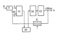
- the phase control circuit shown in the figure serves to to synchronize the clock frequency fn emitted by a voltage-controlled oscillator VCO, which, for example, forms the clock frequency for a digital switching center and is, for example, 4096 kHz, to a reference clock fR which is from another and preferably from a switching center which belongs to a higher hierarchical level of the telecommunications network, is delivered in the course of existing digital signal connections.
- VCO voltage-controlled oscillator
- VCO voltage-controlled oscillator
- this reference clock is fed to one input of the phase discriminator PD, at the other input of which the clock signal emitted by the voltage-controlled oscillator VCO, which is also divided down to 2 kHz by means of a frequency divider PC, arrives . If necessary, the frequency divider PC can be brought into its zero position for the purpose of phase correction.
- a microprocessor MP processes the signals emitted by the phase discriminator in accordance with the determined phase difference and uses them to calculate control values for the voltage-controlled oscillator according to a control algorithm that shapes the character of the control circuit as a P controller or as a PI controller. Conversion can be supplied by a digital-to-analog converter DAC.
- the control circuit In the event of a resynchronization, which comes into question when a clock generator is put into operation, or if the reference clock has been out for a long time, the control circuit initially works as a pure P controller, which means that the frequency of the voltage-controlled oscillator VCO is as fast and close to that as possible Frequency of the reference clock is introduced. This is followed by a switch to operation as a PI controller, which is selected because an existing constant frequency difference cannot be completely compensated for by a pure P controller and, on the other hand, a pure I controller shows unstable behavior.
- the integrator of the control circuit is preset to the control value for the voltage-controlled oscillator that was reached during P-mode. PI operation begins with a small time constant, at for example 30 minutes. This is followed, for example, by a stepwise increase in the time constant in four stages up to a time constant on which the final operation is based, for example approximately 18 hours.
- the relative frequency accuracy i.e. the ratio of the reference clock frequency to the clock frequency of the voltage-controlled oscillator was measured and only then switched to the next value of the time constant of the PI controller when certain threshold values were reached. As long as the previously mentioned tuft disorders occur, such threshold values will not be reached.
Landscapes
- Stabilization Of Oscillater, Synchronisation, Frequency Synthesizers (AREA)
- Synchronisation In Digital Transmission Systems (AREA)
Applications Claiming Priority (2)
| Application Number | Priority Date | Filing Date | Title |
|---|---|---|---|
| DE3823237 | 1988-07-08 | ||
| DE3823237 | 1988-07-08 |
Publications (2)
| Publication Number | Publication Date |
|---|---|
| EP0349966A2 true EP0349966A2 (fr) | 1990-01-10 |
| EP0349966A3 EP0349966A3 (fr) | 1990-03-21 |
Family
ID=6358301
Family Applications (1)
| Application Number | Title | Priority Date | Filing Date |
|---|---|---|---|
| EP89112142A Withdrawn EP0349966A3 (fr) | 1988-07-08 | 1989-07-03 | Méthode de synchronisation d'un générateur d'horloge, en particulier d'un générateur d'horloge d'une centrale téléphonique numérique |
Country Status (1)
| Country | Link |
|---|---|
| EP (1) | EP0349966A3 (fr) |
Cited By (1)
| Publication number | Priority date | Publication date | Assignee | Title |
|---|---|---|---|---|
| EP0536042A1 (fr) * | 1991-10-04 | 1993-04-07 | Alcatel Cit | Dispositif de détection d'accrochage d'une boucle à verrouillage de phase numérique |
Family Cites Families (3)
| Publication number | Priority date | Publication date | Assignee | Title |
|---|---|---|---|---|
| DE2735031C3 (de) * | 1977-08-03 | 1980-05-22 | Siemens Ag, 1000 Berlin Und 8000 Muenchen | Phasenregelkreis |
| DE3120930A1 (de) * | 1981-05-26 | 1982-12-16 | Siemens AG, 1000 Berlin und 8000 München | Integrierbare nachlauf-synchronisationsschaltung |
| FR2546691B1 (fr) * | 1983-05-27 | 1985-07-05 | Cit Alcatel | Base de temps asservie |
-
1989
- 1989-07-03 EP EP89112142A patent/EP0349966A3/fr not_active Withdrawn
Cited By (3)
| Publication number | Priority date | Publication date | Assignee | Title |
|---|---|---|---|---|
| EP0536042A1 (fr) * | 1991-10-04 | 1993-04-07 | Alcatel Cit | Dispositif de détection d'accrochage d'une boucle à verrouillage de phase numérique |
| FR2682237A1 (fr) * | 1991-10-04 | 1993-04-09 | Cit Alcatel | Dispositif de detection d'accrochage d'une boucle a verrouillage de phase. |
| US5268652A (en) * | 1991-10-04 | 1993-12-07 | Alcatel Cit | Circuit for detecting locking of a digital phase locked loop |
Also Published As
| Publication number | Publication date |
|---|---|
| EP0349966A3 (fr) | 1990-03-21 |
Similar Documents
| Publication | Publication Date | Title |
|---|---|---|
| EP0347737B1 (fr) | Méthode de synchronisation de générateurs d'horloge, en particulier de générateurs d'horloge d'une centrale téléphonique numérique | |
| DE2929127C2 (fr) | ||
| DE69112477T2 (de) | Frequenzsynthetisierer mit Phasenregelschleife. | |
| DE3587141T2 (de) | Zentrierschaltung eines spannungsgesteuerten oszillators. | |
| EP0650259B1 (fr) | Circuit générateur de signaux d'horloge | |
| AT400787B (de) | Funk-telefonsystem | |
| DE69300291T2 (de) | Frequenzregelschleife. | |
| EP0530749B1 (fr) | Méthode et dispositif pour la synchronisation d'un générateur d'horloge d'un système de commutation de communication | |
| DE2751021A1 (de) | Anordnung zum synchronisieren von oszillatorsignalen | |
| DE3740795A1 (de) | Schaltungsanordnung zur synchronisation zweier taktsignale | |
| EP0220413B1 (fr) | Circuit d'adaptation individuelle d'une interface série d'un système de traitement de données à la vitesse de transmission d'un partenaire | |
| EP0353616B1 (fr) | Méthode de synchronisation d'une horloge sur une horloge de référence perturbée | |
| EP0349966A2 (fr) | Méthode de synchronisation d'un générateur d'horloge, en particulier d'un générateur d'horloge d'une centrale téléphonique numérique | |
| EP0973263B1 (fr) | Générateur d'horloge et procédé de synchronisation | |
| DE4131063C1 (fr) | ||
| EP0630129A2 (fr) | Méthode de génération d'un signal d'horloge synchronisé avec un circuit d'oscillateur réglable | |
| DE19701209C2 (de) | PLL-Synthesizer und Spektrumanalysator | |
| EP0715412B1 (fr) | Procédé et dispositif d'investigation des variations de phase du signal d'entrée de référence d'une boucle à verrouillage de phase | |
| DE3604965C1 (de) | Verfahren und Schaltungsanordnung zum Synchronisieren eines insbesondere einer Vermittlungseinrichtung zugehoerigen spannungsgesteuerten Oszillators | |
| EP0588050B1 (fr) | Dispositif pour la génération d'un signal d'horloge présentant des absences d'impulsions avec une précision de bit | |
| DE4431415C2 (de) | Verfahren zum Synchronisieren der Ausgangsfrequenzen eines Taktgenerators | |
| EP0898372B1 (fr) | Procédé et dispositif de réglage de la fréquence d'un oscillateur | |
| DE69420610T2 (de) | Frequenzsynthetisierer | |
| EP1903681B1 (fr) | Procédé pour synchronisation de l'horloge d'un appareil électrique ave une horloge de référence et appareil électrique | |
| DE19840976C1 (de) | Verfahren zur Erzeugung eines Taktsignals und entsprechender Taktsignalgenerator |
Legal Events
| Date | Code | Title | Description |
|---|---|---|---|
| PUAI | Public reference made under article 153(3) epc to a published international application that has entered the european phase |
Free format text: ORIGINAL CODE: 0009012 |
|
| AK | Designated contracting states |
Kind code of ref document: A2 Designated state(s): AT BE CH DE ES FR GB GR IT LI NL SE |
|
| PUAL | Search report despatched |
Free format text: ORIGINAL CODE: 0009013 |
|
| AK | Designated contracting states |
Kind code of ref document: A3 Designated state(s): AT BE CH DE ES FR GB GR IT LI NL SE |
|
| 17P | Request for examination filed |
Effective date: 19900410 |
|
| 17Q | First examination report despatched |
Effective date: 19921005 |
|
| STAA | Information on the status of an ep patent application or granted ep patent |
Free format text: STATUS: THE APPLICATION HAS BEEN WITHDRAWN |
|
| 18W | Application withdrawn |
Withdrawal date: 19940301 |