EP0349966A2 - Synchronisation method for a clock generator, especially a clock generator of a digital telephone exchange - Google Patents
Synchronisation method for a clock generator, especially a clock generator of a digital telephone exchange Download PDFInfo
- Publication number
- EP0349966A2 EP0349966A2 EP89112142A EP89112142A EP0349966A2 EP 0349966 A2 EP0349966 A2 EP 0349966A2 EP 89112142 A EP89112142 A EP 89112142A EP 89112142 A EP89112142 A EP 89112142A EP 0349966 A2 EP0349966 A2 EP 0349966A2
- Authority
- EP
- European Patent Office
- Prior art keywords
- clock generator
- clock
- reference clock
- frequency
- mode
- Prior art date
- Legal status (The legal status is an assumption and is not a legal conclusion. Google has not performed a legal analysis and makes no representation as to the accuracy of the status listed.)
- Withdrawn
Links
Images
Classifications
-
- H—ELECTRICITY
- H03—ELECTRONIC CIRCUITRY
- H03L—AUTOMATIC CONTROL, STARTING, SYNCHRONISATION, OR STABILISATION OF GENERATORS OF ELECTRONIC OSCILLATIONS OR PULSES
- H03L7/00—Automatic control of frequency or phase; Synchronisation
- H03L7/06—Automatic control of frequency or phase; Synchronisation using a reference signal applied to a frequency- or phase-locked loop
- H03L7/08—Details of the phase-locked loop
- H03L7/14—Details of the phase-locked loop for assuring constant frequency when supply or correction voltages fail or are interrupted
- H03L7/146—Details of the phase-locked loop for assuring constant frequency when supply or correction voltages fail or are interrupted by using digital means for generating the oscillator control signal
-
- H—ELECTRICITY
- H03—ELECTRONIC CIRCUITRY
- H03L—AUTOMATIC CONTROL, STARTING, SYNCHRONISATION, OR STABILISATION OF GENERATORS OF ELECTRONIC OSCILLATIONS OR PULSES
- H03L7/00—Automatic control of frequency or phase; Synchronisation
- H03L7/06—Automatic control of frequency or phase; Synchronisation using a reference signal applied to a frequency- or phase-locked loop
- H03L7/08—Details of the phase-locked loop
- H03L7/10—Details of the phase-locked loop for assuring initial synchronisation or for broadening the capture range
- H03L7/107—Details of the phase-locked loop for assuring initial synchronisation or for broadening the capture range using a variable transfer function for the loop, e.g. low pass filter having a variable bandwidth
Definitions
- the invention relates to a method for synchronizing a clock generator according to the preamble of patent claim 1.
- phase control circuit which works in normal operation as a proportional / integral controller (PI controller), the behavior of which is the parallel connection of a proportional controller (P controller), in which each input variable is assigned an output variable, and an integral controller (I controller), in which each value of the input variable is opposed to a specific rate of change of the output variable.
- PI controller proportional / integral controller
- P controller proportional controller
- I controller integral controller
- control circuit initially works as a pure P controller in order to bring the frequency of the clock generator as quickly and as close as possible to the clock frequency of the reference clock, and then switch to PI operation.
- the integration time constant of the I part of the PI controller in normal operation is of the order of 18 hours, which ensures that in the event of a temporary failure of the reference clock, sufficient memory accuracy is available to ensure compliance with the deviation limits of the clock frequency of the clock generator recommended by CCITTT .
- the object of the invention is now to provide a method which improves the conditions in the resynchronization of a clock generator in view of the problems mentioned above. This object is achieved by a method with the features specified in the characterizing part of patent claim 1.
- the integrator of the control circuit settled relatively quickly, so that a temporary failure of the reference clock cannot lead to inadmissible deviations even at this stage. Errors in the frequency offset in the integrator, which can be attributed to jitter and wander, are eliminated sufficiently quickly.
- the time constant of the control circuit is gradually increased to its final value each time fixed values of the relative frequency accuracy of the clock generator are reached. This ensures that tufts of the reference clock, ie short-term frequency disturbances, after which the reference clock returns to its original characteristic values or phase jumps in the reference clock, have no influence on the control.
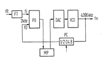
- the phase control circuit shown in the figure serves to to synchronize the clock frequency fn emitted by a voltage-controlled oscillator VCO, which, for example, forms the clock frequency for a digital switching center and is, for example, 4096 kHz, to a reference clock fR which is from another and preferably from a switching center which belongs to a higher hierarchical level of the telecommunications network, is delivered in the course of existing digital signal connections.
- VCO voltage-controlled oscillator
- VCO voltage-controlled oscillator
- this reference clock is fed to one input of the phase discriminator PD, at the other input of which the clock signal emitted by the voltage-controlled oscillator VCO, which is also divided down to 2 kHz by means of a frequency divider PC, arrives . If necessary, the frequency divider PC can be brought into its zero position for the purpose of phase correction.
- a microprocessor MP processes the signals emitted by the phase discriminator in accordance with the determined phase difference and uses them to calculate control values for the voltage-controlled oscillator according to a control algorithm that shapes the character of the control circuit as a P controller or as a PI controller. Conversion can be supplied by a digital-to-analog converter DAC.
- the control circuit In the event of a resynchronization, which comes into question when a clock generator is put into operation, or if the reference clock has been out for a long time, the control circuit initially works as a pure P controller, which means that the frequency of the voltage-controlled oscillator VCO is as fast and close to that as possible Frequency of the reference clock is introduced. This is followed by a switch to operation as a PI controller, which is selected because an existing constant frequency difference cannot be completely compensated for by a pure P controller and, on the other hand, a pure I controller shows unstable behavior.
- the integrator of the control circuit is preset to the control value for the voltage-controlled oscillator that was reached during P-mode. PI operation begins with a small time constant, at for example 30 minutes. This is followed, for example, by a stepwise increase in the time constant in four stages up to a time constant on which the final operation is based, for example approximately 18 hours.
- the relative frequency accuracy i.e. the ratio of the reference clock frequency to the clock frequency of the voltage-controlled oscillator was measured and only then switched to the next value of the time constant of the PI controller when certain threshold values were reached. As long as the previously mentioned tuft disorders occur, such threshold values will not be reached.
Abstract
Description
Die Erfindung betrifft ein Verfahren zur Synchronisation eines Taktgenerators gemäß dem Oberbegriff des Patentanspruchs 1.The invention relates to a method for synchronizing a clock generator according to the preamble of patent claim 1.
Es wird demnach die Verwendung einer Phasenregelschaltung vorausgesetzt, die im Normalbetrieb als Proportional-/Integral-Regler (PI-Regler) arbeitet, dessen Verhalten der Parallelschaltung eines Proportionalreglers (P-Regler), bei dem jeder Eingangsgröße eine Ausgangsgröße zugeordnet ist, und eines Integralreglers (I-Regler) entspricht, bei dem jedem Wert der Eingangsgröße eine bestimmte Änderungsgeschwindigkeit der Ausgangsgröße gegenübersteht.It is therefore assumed that a phase control circuit is used, which works in normal operation as a proportional / integral controller (PI controller), the behavior of which is the parallel connection of a proportional controller (P controller), in which each input variable is assigned an output variable, and an integral controller (I controller), in which each value of the input variable is opposed to a specific rate of change of the output variable.
Es wird ferner vorausgesetzt, daß in der Phase einer Neusynchronisation die Regelschaltung zunächst als reiner P-Regler arbeitet, um die Frequenz des Taktgenerators möglichst schnell und nahe an die Taktfrequenz des Referenztaktes heranzuführen, und danach auf den PI-Betrieb umgeschaltet wird. Die Integrationszeitkonstante des I-Teils des PI-Reglers liegt im Normalfallbetrieb in der Größenordnung von 18 Stunden, womit gewährleistet ist, daß bei einem vorübergehenden Ausfall des Referenztaktes eine ausreichende Speichergenauigkeit vorhanden ist, die die Einhaltung der von CCITTT empfohlenen Abweichungsgrenzen der Taktfrequenz des Taktgenerators gewährleistet. Bei solchen großen Zeitkonstanten dauert es allerdings entsprechend lange bis der Integrator des PI-Reglers eingeschwungen ist, so daß bei einem Ausfall des Referenztaktes in diesem Stadium mit einer Taktfrequenz des Taktgenerators weitergearbeitet wird, die relativ schlecht mit der Frequenz des Referenztaktes übereinstimmt. Hinzu kommt, daß hochfrequente Phasenschwankungen (Jitter) und niederfrequente Phasenschwankungen (Wander), mit denen der Referenztakt aufgrund seiner Übertragung, im Falle der Synchronisation eines Taktgenerators einer digitalen Fernsprechvermittlungsstelle, also aufgrund seiner Übertragung über bestehende Digitalsignalverbindungen von anderen Vermittlungsstellen her, behaftet ist, zu fehlerhaften Frequenzablagen im Integrator führen. Diese werden zwar im Zuge des Regelprozesses abgebaut werden, wegen der erwähnten großen Zeitkonstanten allerdings entsprechend langsam.It is also assumed that in the phase of resynchronization, the control circuit initially works as a pure P controller in order to bring the frequency of the clock generator as quickly and as close as possible to the clock frequency of the reference clock, and then switch to PI operation. The integration time constant of the I part of the PI controller in normal operation is of the order of 18 hours, which ensures that in the event of a temporary failure of the reference clock, sufficient memory accuracy is available to ensure compliance with the deviation limits of the clock frequency of the clock generator recommended by CCITTT . With such large time constants, however, it takes a correspondingly long time for the integrator of the PI controller to settle in, so that if the reference clock fails at this stage, the clock frequency of the clock generator continues to work which corresponds relatively poorly to the frequency of the reference clock. Added to this is the fact that high-frequency phase fluctuations (jitter) and low-frequency phase fluctuations (wander) with which the reference clock due to its transmission, in the case of synchronization of a clock generator a digital telephone exchange, that is to say due to its transmission via existing digital signal connections from other exchanges, can lead to incorrect frequency storage in the integrator. Although these will be reduced in the course of the control process, due to the large time constants mentioned, however, they will be correspondingly slow.
Die Aufgabe der Erfindung besteht nun darin, ein Verfahfen anzugeben, das die Verhältnisse bei der Neusynchronisation eines Taktgenerators im Hinblick auf die oben erwähnten Probleme verbessert. Diese Aufgabe wird durch ein Verfahren mit den im Kennzeichen des Patentanspruchs 1 angegebenen Merkmalen gelöst.The object of the invention is now to provide a method which improves the conditions in the resynchronization of a clock generator in view of the problems mentioned above. This object is achieved by a method with the features specified in the characterizing part of patent claim 1.
Wegen der bei Beginn des PI-Betriebs zunächst niedrigen Zeitkonstanten ist der Integrator der Regelschaltung relativ schnell eingeschwungen, so daß ein vorübergehender Ausfall des Referenztaktes auch in diesem Stadium nicht zu unzulässigen Abweichungen führen kann. Fehler in der Frequenzablage im Integrator, die auf Jitter und Wander zurückzuführen sind, werden ausreichend schnell abgebaut.Because of the initially low time constant at the start of PI operation, the integrator of the control circuit settled relatively quickly, so that a temporary failure of the reference clock cannot lead to inadmissible deviations even at this stage. Errors in the frequency offset in the integrator, which can be attributed to jitter and wander, are eliminated sufficiently quickly.
Gemäß einer weiteren Ausgestaltung der Erfindung erfolgt die stufenweise Erhöhung der Zeitkonstanten der Regelschaltung auf ihren Endwert jeweils bei Erreichen festgelegter Werte der relativen Frequenzgenauigkeit des Taktgenerators. Es ist hiermit gewährleistet, daß Büschelstörungen des Referenztaktes, also kurzzeitige Frequenzstörungen, nach deren Wegfall der Referenztakt wieder seine ursprünglichen Kennwerte annimmt oder Phasensprünge des Referenztaktes, auf die Regelung keinen Einfluß haben.According to a further embodiment of the invention, the time constant of the control circuit is gradually increased to its final value each time fixed values of the relative frequency accuracy of the clock generator are reached. This ensures that tufts of the reference clock, ie short-term frequency disturbances, after which the reference clock returns to its original characteristic values or phase jumps in the reference clock, have no influence on the control.
Nachstehend wird die Erfindung anhand eines Ausführungsbeispiels unter Bezugnahme auf eine Figur, die eine Anordnung zur Durchführung des erfindungsgemäßen Verfahrens zeigt, näher erläutert.The invention is explained in more detail below on the basis of an exemplary embodiment with reference to a figure which shows an arrangement for carrying out the method according to the invention.
Die in der Figur dargestellte Phasenregelschaltung dient dazu, die von einem spannungsgesteuerten Oszillator VCO abgegebene Taktfrequenz fn, die beispielsweise die Taktfrequenz für eine digitale Vermittlungsstelle bildet und beispielsweise 4096 kHz beträgt, auf einen Referenztakt fR aufzusynchronisieren, der von einer anderen und vorzugsweise von einer Vermittlungsstelle her, die einer höheren Hierarchieebene des Fernmeldenetzes angehört, im Zuge bestehender Digitalsignalverbindungen geliefert wird. Dieser Referenztakt wird nach einer Frequenzuntersetzung mittels eines Frequenzteilers FT auf eine Frequenz von hier 2 kHz dem einen Eingang des Phasendiskriminators PD zugeführt, an dessen anderen Eingang das vom spannungsgesteuerten Oszillator VCO abgegebene Taktsignal, das mittels eines Frequenzteilers PC ebenfalls auf 2 kHz heruntergeteilt ist, gelangt. Der Frequenzteiler PC kann im Bedarfsfall zum Zwecke der Phasenkorrektur jeweils gezielt in seine Nullstellung gebracht werden.The phase control circuit shown in the figure serves to to synchronize the clock frequency fn emitted by a voltage-controlled oscillator VCO, which, for example, forms the clock frequency for a digital switching center and is, for example, 4096 kHz, to a reference clock fR which is from another and preferably from a switching center which belongs to a higher hierarchical level of the telecommunications network, is delivered in the course of existing digital signal connections. After a frequency reduction by means of a frequency divider FT to a frequency of here 2 kHz, this reference clock is fed to one input of the phase discriminator PD, at the other input of which the clock signal emitted by the voltage-controlled oscillator VCO, which is also divided down to 2 kHz by means of a frequency divider PC, arrives . If necessary, the frequency divider PC can be brought into its zero position for the purpose of phase correction.
Ein Mikroprozessor MP verarbeitet die vom Phasendiskriminator entsprechend der ermittelten Phasendifferenz abgegebenen Signale und errechnet daraus gemäß einem Regelalgorythmus, der dem Charakter der Regelschaltung als P-Regler oder als PI-Regler prägt, Stellwerte für den spannungsgesteuerten Oszillator, die diesem nach einer Digital-Analog-Wandlung durch einen Digital-Analog-Wandler DAC zugeführt werden.A microprocessor MP processes the signals emitted by the phase discriminator in accordance with the determined phase difference and uses them to calculate control values for the voltage-controlled oscillator according to a control algorithm that shapes the character of the control circuit as a P controller or as a PI controller. Conversion can be supplied by a digital-to-analog converter DAC.
Bei einer Neusynchronisation, die bei Inbetriebnahme eines Taktgenerators in Frage kommt, bzw. dann wenn der Referenztakt über eine längere Zeit hinweg ausgefallen war, arbeitet die Regelschaltung zunächst als reiner P-Regler, wodurch die Frequenz des spannungsgesteuerten Oszillators VCO möglichst schnell und nahe an die Frequenz des Referenztaktes herangeführt wird. Danach erfolgt eine Umschaltung auf den Betrieb als PI-Regler, der gewählt wird, weil durch einen reinen P-Regler eine bestehende konstante Frequenzdifferenz nicht völlig ausgeregelt werden kann und andererseits ein reiner I-Regler ein instabiles Verhalten zeigt. Der Integrator der Regelschaltung wird dabei auf den während des P-Betriebs erreichten Stellwert für den spannungsgesteuerten Oszillator voreingestellt. Der PI-Betrieb beginnt zunächst unter Zugrundelegung einer kleinen Zeitkonstanten, bei spielsweise 30 Minuten. Danach erfolgt beispielsweise in vier Stufen eine stufenweise Erhöhung der Zeitkonstanten bis zu einer dem endgültigen Betrieb zugrunde liegenden Zeitkonstanten von beispielsweise ca. 18 Stunden.In the event of a resynchronization, which comes into question when a clock generator is put into operation, or if the reference clock has been out for a long time, the control circuit initially works as a pure P controller, which means that the frequency of the voltage-controlled oscillator VCO is as fast and close to that as possible Frequency of the reference clock is introduced. This is followed by a switch to operation as a PI controller, which is selected because an existing constant frequency difference cannot be completely compensated for by a pure P controller and, on the other hand, a pure I controller shows unstable behavior. The integrator of the control circuit is preset to the control value for the voltage-controlled oscillator that was reached during P-mode. PI operation begins with a small time constant, at for example 30 minutes. This is followed, for example, by a stepwise increase in the time constant in four stages up to a time constant on which the final operation is based, for example approximately 18 hours.
Sofern vorausgesetzt werden kann, daß der Referenztakt lediglich mit sinusförmigen Jitter- bzw. Wanderstörungen behaftet ist, kann diese Erhöhung in fest vorgegebenen Zeitintervallen erfolgen, da der Regelkreis als Filter wirkt und damit der spannungsgesteuerte Oszillator immer auf den Mittelwert der Referenztaktfrequenz eingestellt wird.If it can be assumed that the reference clock is only affected by sinusoidal jitter or wandering disturbances, this increase can take place at fixed predetermined time intervals, since the control loop acts as a filter and the voltage-controlled oscillator is therefore always set to the average value of the reference clock frequency.
Wenn nun aber sogenannte Büschelstörungen also kurzzeitige erhebliche Frequenzänderungen der Referenztaktfrequenz auftreten, die durch Einstreuungen von außen beispielsweise durch Einflüsse des U-Bahnnetzes entstehen oder sonstige Phasensprünge des Referenztaktes auftreten, dann wird ein unzutreffender Mittelwert der Referenztaktfrequenz ermittelt und dementsprechend der Aufsynchronisationsprozeß beeinträchtigt. Gemäß einer weiteren Ausgestaltung der Erfindung wird daher die relative Frequenzgenauigkeit, d.h. das Verhältnis von Referenztaktfrequenz zur Taktfrequenz des spannungsgesteuerten Oszillators gemessen und erst dann wenn bestimmte Schwellwerte erreicht sind, auf den jeweils nächsten Wert der Zeitkonstanten des PI-Reglers umgeschaltet. Solange die zuvor erwähnten Büschelstörungen auftreten, werden solche Schwellwerte nicht erreicht werden können.However, if so-called tuft disturbances occur, that is, there are brief, significant frequency changes in the reference clock frequency, which occur due to interference from outside, for example due to influences from the subway network, or other phase jumps in the reference clock occur, then an incorrect mean value of the reference clock frequency is determined and the synchronization process is impaired accordingly. According to a further embodiment of the invention, the relative frequency accuracy, i.e. the ratio of the reference clock frequency to the clock frequency of the voltage-controlled oscillator was measured and only then switched to the next value of the time constant of the PI controller when certain threshold values were reached. As long as the previously mentioned tuft disorders occur, such threshold values will not be reached.
Claims (2)
dadurch gekennzeichnet,
daß der PI-Betrieb unter Zugrundelegung einer niedrigen Zeitkonstanten beginnt, die danach stufenweise auf ihren Endwert erhöht wird.1.Procedure for synchronizing a clock generator, in particular clock generator of a digital telecommunications exchange, to a reference clock which, due to its transmission, is subject to periodic phase fluctuations (jitter and wander) with the aid of a phase control circuit which, in the course of a re-synchronization, initially as a proportional controller (P mode ) works to bring the clock frequency of the clock generator to the reference clock as quickly as possible and then switches to a mode of operation as a proportional integral controller (PI) mode, the integrator of the control circuit being preset to the manipulated value for the clock generator achieved during P mode ,
characterized,
that the PI operation starts on the basis of a low time constant, which is then gradually increased to its final value.
dadurch gekennzeichnet, daß die stufenweise Erhöhung der Zeitkonstanten jeweils bei Erreichen festgelegter Werte der relativen Frequenzgenauigkeit des Taktgenerators erfolgt.2) Method according to claim 1,
characterized in that the step-by-step increase in the time constant takes place each time fixed values of the relative frequency accuracy of the clock generator are reached.
Applications Claiming Priority (2)
| Application Number | Priority Date | Filing Date | Title |
|---|---|---|---|
| DE3823237 | 1988-07-08 | ||
| DE3823237 | 1988-07-08 |
Publications (2)
| Publication Number | Publication Date |
|---|---|
| EP0349966A2 true EP0349966A2 (en) | 1990-01-10 |
| EP0349966A3 EP0349966A3 (en) | 1990-03-21 |
Family
ID=6358301
Family Applications (1)
| Application Number | Title | Priority Date | Filing Date |
|---|---|---|---|
| EP89112142A Withdrawn EP0349966A3 (en) | 1988-07-08 | 1989-07-03 | Synchronisation method for a clock generator, especially a clock generator of a digital telephone exchange |
Country Status (1)
| Country | Link |
|---|---|
| EP (1) | EP0349966A3 (en) |
Cited By (1)
| Publication number | Priority date | Publication date | Assignee | Title |
|---|---|---|---|---|
| EP0536042A1 (en) * | 1991-10-04 | 1993-04-07 | Alcatel Cit | Phase lock detection device for a digital PLL |
Citations (3)
| Publication number | Priority date | Publication date | Assignee | Title |
|---|---|---|---|---|
| DE2735031A1 (en) * | 1977-08-03 | 1979-02-08 | Siemens Ag | Automatic phase control circuit - has switching stage and filter which compares mean phase differences with limits and controls oscillator |
| DE3120930A1 (en) * | 1981-05-26 | 1982-12-16 | Siemens AG, 1000 Berlin und 8000 München | Integrable tracking-type synchronisation circuit |
| FR2546691A1 (en) * | 1983-05-27 | 1984-11-30 | Cit Alcatel | BASIS OF TIME SERVED |
-
1989
- 1989-07-03 EP EP89112142A patent/EP0349966A3/en not_active Withdrawn
Patent Citations (3)
| Publication number | Priority date | Publication date | Assignee | Title |
|---|---|---|---|---|
| DE2735031A1 (en) * | 1977-08-03 | 1979-02-08 | Siemens Ag | Automatic phase control circuit - has switching stage and filter which compares mean phase differences with limits and controls oscillator |
| DE3120930A1 (en) * | 1981-05-26 | 1982-12-16 | Siemens AG, 1000 Berlin und 8000 München | Integrable tracking-type synchronisation circuit |
| FR2546691A1 (en) * | 1983-05-27 | 1984-11-30 | Cit Alcatel | BASIS OF TIME SERVED |
Cited By (3)
| Publication number | Priority date | Publication date | Assignee | Title |
|---|---|---|---|---|
| EP0536042A1 (en) * | 1991-10-04 | 1993-04-07 | Alcatel Cit | Phase lock detection device for a digital PLL |
| FR2682237A1 (en) * | 1991-10-04 | 1993-04-09 | Cit Alcatel | DEVICE FOR DETECTING THE ATTACHMENT OF A PHASE LOCKED BUCKLE. |
| US5268652A (en) * | 1991-10-04 | 1993-12-07 | Alcatel Cit | Circuit for detecting locking of a digital phase locked loop |
Also Published As
| Publication number | Publication date |
|---|---|
| EP0349966A3 (en) | 1990-03-21 |
Similar Documents
| Publication | Publication Date | Title |
|---|---|---|
| EP0347737B1 (en) | Synchronisation method for a clock generator, especially of a clock generator of a digital telephone exchange | |
| DE2751021C3 (en) | Synchronizing circuit for an oscillator circuit | |
| EP1216509B1 (en) | Circuit arrangement for generating a clock-pulse signal having a frequency synchronous with a reference clock-pulse signal | |
| EP0530749B1 (en) | Method and apparatus for synchronising a clock-circuit of a switching communication system | |
| DE3805112A1 (en) | CLOCK SIGNAL GENERATION CIRCUIT FOR TELEVISION RECEIVERS | |
| EP0220413B1 (en) | Circuit for the individual adaptation of a data-processing system serial interface to the transmission speed of a communication partner | |
| EP0166749B1 (en) | Phase regulation circuit | |
| EP0353616B1 (en) | Method for clock synchronization on a disturbed reference clock | |
| EP0349966A2 (en) | Synchronisation method for a clock generator, especially a clock generator of a digital telephone exchange | |
| EP0973263B1 (en) | Clock generator and synchronisation method | |
| DE4131063C1 (en) | ||
| DE4442306C2 (en) | Method and arrangement for determining phase changes in a reference input signal of a phase locked loop | |
| DE19701209C2 (en) | PLL synthesizer and spectrum analyzer | |
| DE3604965C1 (en) | Method and circuit arrangement for synchronizing a voltage-controlled oscillator, in particular a switching device | |
| DE10132403A1 (en) | Method and device for clock recovery from a data signal | |
| DE4431415C2 (en) | Method for synchronizing the output frequencies of a clock generator | |
| EP0588050B1 (en) | Arrangement for generating a clock signal having missing pulses with a bit precision | |
| EP1159807A1 (en) | Production of clock signals for sampling data signals with different rates using a phase-locking loop | |
| EP1903681B1 (en) | Method for synchronising the clock of an electrical apparatus with a reference clock and electrical apparatus | |
| EP1374405B1 (en) | Frequency closed loop for frequency modulation | |
| DE19840976C1 (en) | Clock-signal generation procedure especially for digital telecommunications network facility | |
| EP0438620B1 (en) | Method and circuit arrangement for the minimization of an a.c. component in the phase detector output signal of a phase locked loop | |
| DE4121450C1 (en) | Clock signal circuit for communications system - has control input of VCO supplied with required output of voltage comparator in dependence on master or slave clock operating mode | |
| DE2653475A1 (en) | Frequency interpolation circuit and process - producing low variable frequency by addition or subtraction of pulses and superimposing on standard HF | |
| DE19947095A1 (en) | Frame clock synchronisation arrangement in data transmission system |
Legal Events
| Date | Code | Title | Description |
|---|---|---|---|
| PUAI | Public reference made under article 153(3) epc to a published international application that has entered the european phase |
Free format text: ORIGINAL CODE: 0009012 |
|
| AK | Designated contracting states |
Kind code of ref document: A2 Designated state(s): AT BE CH DE ES FR GB GR IT LI NL SE |
|
| PUAL | Search report despatched |
Free format text: ORIGINAL CODE: 0009013 |
|
| AK | Designated contracting states |
Kind code of ref document: A3 Designated state(s): AT BE CH DE ES FR GB GR IT LI NL SE |
|
| 17P | Request for examination filed |
Effective date: 19900410 |
|
| 17Q | First examination report despatched |
Effective date: 19921005 |
|
| STAA | Information on the status of an ep patent application or granted ep patent |
Free format text: STATUS: THE APPLICATION HAS BEEN WITHDRAWN |
|
| 18W | Application withdrawn |
Withdrawal date: 19940301 |