EP0349872B1 - Procédé et dispositif pour la fabrication de corps creux en matière thermoplastique - Google Patents
Procédé et dispositif pour la fabrication de corps creux en matière thermoplastique Download PDFInfo
- Publication number
- EP0349872B1 EP0349872B1 EP89111570A EP89111570A EP0349872B1 EP 0349872 B1 EP0349872 B1 EP 0349872B1 EP 89111570 A EP89111570 A EP 89111570A EP 89111570 A EP89111570 A EP 89111570A EP 0349872 B1 EP0349872 B1 EP 0349872B1
- Authority
- EP
- European Patent Office
- Prior art keywords
- laminate
- annular piston
- storage chamber
- annular
- flows
- Prior art date
- Legal status (The legal status is an assumption and is not a legal conclusion. Google has not performed a legal analysis and makes no representation as to the accuracy of the status listed.)
- Expired - Lifetime
Links
- 239000000463 material Substances 0.000 title claims abstract description 85
- 238000000034 method Methods 0.000 title claims abstract description 22
- 238000004519 manufacturing process Methods 0.000 title abstract description 8
- 229920001169 thermoplastic Polymers 0.000 title 1
- 239000004416 thermosoftening plastic Substances 0.000 title 1
- 238000003860 storage Methods 0.000 claims abstract description 71
- 238000001125 extrusion Methods 0.000 claims abstract description 52
- 230000008569 process Effects 0.000 claims abstract description 10
- 239000012815 thermoplastic material Substances 0.000 claims abstract description 6
- 238000010101 extrusion blow moulding Methods 0.000 claims abstract description 5
- 239000004033 plastic Substances 0.000 claims description 9
- 229920003023 plastic Polymers 0.000 claims description 9
- 230000001427 coherent effect Effects 0.000 claims description 2
- 238000011144 upstream manufacturing Methods 0.000 claims 1
- 239000010410 layer Substances 0.000 description 53
- 230000015572 biosynthetic process Effects 0.000 description 24
- 230000009467 reduction Effects 0.000 description 8
- 238000005192 partition Methods 0.000 description 5
- 239000004698 Polyethylene Substances 0.000 description 4
- 238000009826 distribution Methods 0.000 description 4
- -1 polyethylene Polymers 0.000 description 4
- 229920000573 polyethylene Polymers 0.000 description 4
- 239000004952 Polyamide Substances 0.000 description 3
- 239000002318 adhesion promoter Substances 0.000 description 3
- 230000004888 barrier function Effects 0.000 description 3
- 238000010276 construction Methods 0.000 description 3
- 229920002647 polyamide Polymers 0.000 description 3
- 230000008901 benefit Effects 0.000 description 2
- 230000008859 change Effects 0.000 description 2
- 238000009792 diffusion process Methods 0.000 description 2
- 239000000446 fuel Substances 0.000 description 2
- 239000002828 fuel tank Substances 0.000 description 2
- 229920000098 polyolefin Polymers 0.000 description 2
- 230000008961 swelling Effects 0.000 description 2
- 230000009471 action Effects 0.000 description 1
- 239000012790 adhesive layer Substances 0.000 description 1
- 230000000712 assembly Effects 0.000 description 1
- 238000000429 assembly Methods 0.000 description 1
- 238000007664 blowing Methods 0.000 description 1
- 230000002349 favourable effect Effects 0.000 description 1
- 239000002648 laminated material Substances 0.000 description 1
Images


Classifications
-
- B—PERFORMING OPERATIONS; TRANSPORTING
- B29—WORKING OF PLASTICS; WORKING OF SUBSTANCES IN A PLASTIC STATE IN GENERAL
- B29C—SHAPING OR JOINING OF PLASTICS; SHAPING OF MATERIAL IN A PLASTIC STATE, NOT OTHERWISE PROVIDED FOR; AFTER-TREATMENT OF THE SHAPED PRODUCTS, e.g. REPAIRING
- B29C48/00—Extrusion moulding, i.e. expressing the moulding material through a die or nozzle which imparts the desired form; Apparatus therefor
- B29C48/03—Extrusion moulding, i.e. expressing the moulding material through a die or nozzle which imparts the desired form; Apparatus therefor characterised by the shape of the extruded material at extrusion
- B29C48/09—Articles with cross-sections having partially or fully enclosed cavities, e.g. pipes or channels
-
- B—PERFORMING OPERATIONS; TRANSPORTING
- B29—WORKING OF PLASTICS; WORKING OF SUBSTANCES IN A PLASTIC STATE IN GENERAL
- B29C—SHAPING OR JOINING OF PLASTICS; SHAPING OF MATERIAL IN A PLASTIC STATE, NOT OTHERWISE PROVIDED FOR; AFTER-TREATMENT OF THE SHAPED PRODUCTS, e.g. REPAIRING
- B29C48/00—Extrusion moulding, i.e. expressing the moulding material through a die or nozzle which imparts the desired form; Apparatus therefor
- B29C48/16—Articles comprising two or more components, e.g. co-extruded layers
- B29C48/18—Articles comprising two or more components, e.g. co-extruded layers the components being layers
- B29C48/21—Articles comprising two or more components, e.g. co-extruded layers the components being layers the layers being joined at their surfaces
-
- B—PERFORMING OPERATIONS; TRANSPORTING
- B29—WORKING OF PLASTICS; WORKING OF SUBSTANCES IN A PLASTIC STATE IN GENERAL
- B29C—SHAPING OR JOINING OF PLASTICS; SHAPING OF MATERIAL IN A PLASTIC STATE, NOT OTHERWISE PROVIDED FOR; AFTER-TREATMENT OF THE SHAPED PRODUCTS, e.g. REPAIRING
- B29C48/00—Extrusion moulding, i.e. expressing the moulding material through a die or nozzle which imparts the desired form; Apparatus therefor
- B29C48/25—Component parts, details or accessories; Auxiliary operations
- B29C48/30—Extrusion nozzles or dies
- B29C48/32—Extrusion nozzles or dies with annular openings, e.g. for forming tubular articles
- B29C48/335—Multiple annular extrusion nozzles in coaxial arrangement, e.g. for making multi-layered tubular articles
- B29C48/337—Multiple annular extrusion nozzles in coaxial arrangement, e.g. for making multi-layered tubular articles the components merging at a common location
- B29C48/338—Multiple annular extrusion nozzles in coaxial arrangement, e.g. for making multi-layered tubular articles the components merging at a common location using a die with concentric parts, e.g. rings, cylinders
-
- B—PERFORMING OPERATIONS; TRANSPORTING
- B29—WORKING OF PLASTICS; WORKING OF SUBSTANCES IN A PLASTIC STATE IN GENERAL
- B29C—SHAPING OR JOINING OF PLASTICS; SHAPING OF MATERIAL IN A PLASTIC STATE, NOT OTHERWISE PROVIDED FOR; AFTER-TREATMENT OF THE SHAPED PRODUCTS, e.g. REPAIRING
- B29C48/00—Extrusion moulding, i.e. expressing the moulding material through a die or nozzle which imparts the desired form; Apparatus therefor
- B29C48/25—Component parts, details or accessories; Auxiliary operations
- B29C48/36—Means for plasticising or homogenising the moulding material or forcing it through the nozzle or die
- B29C48/475—Means for plasticising or homogenising the moulding material or forcing it through the nozzle or die using pistons, accumulators or press rams
- B29C48/48—Two or more rams or pistons
-
- B—PERFORMING OPERATIONS; TRANSPORTING
- B29—WORKING OF PLASTICS; WORKING OF SUBSTANCES IN A PLASTIC STATE IN GENERAL
- B29C—SHAPING OR JOINING OF PLASTICS; SHAPING OF MATERIAL IN A PLASTIC STATE, NOT OTHERWISE PROVIDED FOR; AFTER-TREATMENT OF THE SHAPED PRODUCTS, e.g. REPAIRING
- B29C48/00—Extrusion moulding, i.e. expressing the moulding material through a die or nozzle which imparts the desired form; Apparatus therefor
- B29C48/03—Extrusion moulding, i.e. expressing the moulding material through a die or nozzle which imparts the desired form; Apparatus therefor characterised by the shape of the extruded material at extrusion
- B29C48/09—Articles with cross-sections having partially or fully enclosed cavities, e.g. pipes or channels
- B29C48/10—Articles with cross-sections having partially or fully enclosed cavities, e.g. pipes or channels flexible, e.g. blown foils
-
- B—PERFORMING OPERATIONS; TRANSPORTING
- B29—WORKING OF PLASTICS; WORKING OF SUBSTANCES IN A PLASTIC STATE IN GENERAL
- B29C—SHAPING OR JOINING OF PLASTICS; SHAPING OF MATERIAL IN A PLASTIC STATE, NOT OTHERWISE PROVIDED FOR; AFTER-TREATMENT OF THE SHAPED PRODUCTS, e.g. REPAIRING
- B29C49/00—Blow-moulding, i.e. blowing a preform or parison to a desired shape within a mould; Apparatus therefor
- B29C49/02—Combined blow-moulding and manufacture of the preform or the parison
- B29C49/04—Extrusion blow-moulding
- B29C49/041—Extrusion blow-moulding using an accumulator head
Definitions
- the invention relates to a method and a device for producing hollow bodies made of thermoplastic materials, the wall of which is formed as a laminate, which consists of several interconnected layers of at least two plastics with different properties, by means of extrusion blow molding, firstly tubular preforms, the wall of which has a corresponding number of layers which are produced in batches using an extrusion unit which has at least two extruders and a common extrusion head which is provided with an annular storage space for the laminate, an annular piston for emptying the storage space and an extrusion opening through which the preforms are extruded, with all material streams entering the extrusion head, from which the individual layers of the laminate are formed, being guided through the annular piston and into the transverse piston therein be cut into the shape of a ring.
- the procedure is such that all material flows are connected to one another within the annular piston to form the end laminate from which the wall of the hollow body is formed, and thereafter the end laminate formed in this way through an annular channel which widens in the shape of a funnel cut in the ring piston flows towards the storage space.
- the annular piston In the area of the annular piston in which the individual layers are connected to form the end laminate, the latter has a thickness, that is to say a radial extension, which is substantially less than the radial extension, that is to say the width of the storage space.
- a laminate formation point with a small radial extension that is to say with a small thickness of the laminate at the time of its formation, has the consequence that the individual material flows connecting to the laminate have a correspondingly high speed, with the result that there are instantaneous speed differences between the individual flows the laminate formation are correspondingly large, because the relative layer thicknesses of the laminate result from the corresponding ratios of the material flows. This means that with larger differences in thickness between the individual layers, very different flow velocities arise.
- the invention is therefore based on the object of designing a method and apparatus of the type described in the introduction in such a way that the construction of the Extrusion head an end laminate can be produced, which is formed as evenly as possible and free of interference.
- the invention proposes that the material flows ring-shaped in cross-section from the ring piston at its end facing the extrusion opening, flow individually from the ring piston into the storage space and unite in the latter to form a laminate.
- the procedure is such that the material flows emerge from the face of the annular piston, so that the material flows, which each form the outer and inner layers of the laminate, come into contact with the outer and inner boundary walls of the storage space only at the moment of the laminate formation.
- the stored final laminate does not perform any significant movement after it has been formed relative to the wall of the storage space until the following emptying stroke. This favors the uniformity of the formation of the final laminate.
- the laminate formation in the storage space prevents the annular piston from being provided with a special channel section within which the laminate is brought to the radial extent of the storage space in the direction of flow. Rather, according to a further proposal of the invention, it is possible that the radial extent of the laminate formation area corresponds approximately to the radial extent of the storage space. This means that the entirety of the material flows leaving the annular piston at its end facing the extrusion opening of the extrusion head has a radial extent when entering the storage space, which corresponds approximately to the radial extent of the storage space.
- Such a procedure has the advantage that the laminate is generally in the moment its formation has its greatest thickness and, in the course of the further deformations to the preform, essentially only experiences a reduction in its thickness. This represents a stretching process that is always unique.
- An increase in the thickness of the laminate requires a swelling or upsetting process or swelling or upsetting currents in which there is a risk that the laminate with its various layers will be disturbed. This problem is always present, so that efforts are made to carry out the necessary reshaping within the extrusion head as a reduction in thickness or stretching of the laminate.
- the speed of the individual streams in the laminate formation area is also of great importance.
- the Speeds with which the individual layers meet in the laminate formation area and are connected to one another should preferably not differ from one another. At least the differences between the speeds of the individual material flows, especially in the laminate formation area, should be as small as possible.
- the invention further proposes that the thickness, ie the radial dimension, of the individual material flows leaving the piston is essentially proportional to the thickness of the layers to be formed from them in the end laminate stored in the storage space.
- Hollow bodies, in particular containers, produced in the extrusion blow molding process are in many cases produced in multiple layers, so that the wall of the hollow body meets different requirements that cannot be met by a single plastic.
- One example is his fuel tanks, which must have sufficient mechanical strength, but without the fuel being allowed to diffuse through the container wall in appreciable amounts.
- the properties relating to mechanical strength, while taking economic requirements into account, are currently best met by plastics belonging to the group of polyolefins.
- the polyethylene used in many cases has the disadvantage that it allows fuel to diffuse through. Therefore, the wall of a fuel tank is optionally provided with a diffusion barrier in the form of a layer, for example made of polyamide.
- such an end laminate can have seven or more layers, the individual layers again being able to have different thicknesses depending on their function and the nature of the material forming them.
- the layer (s) made of polyolefin will be much thicker than the barrier layer (s), which should prevent diffusion through and the adhesion promoter layer (s), both of which also consist of materials that are essential are more expensive than, for example, polyethylene, which is used in many cases for the support layer (s) of the wall that determine the mechanical strength.
- the speed differences in the aforementioned condition approximately correspond to the differences in the layer thicknesses. Since the differences in the thickness of the individual layers can be very large, for example in a ratio of more than 1:10 to one another, the speed differences between the individual material flows at the laminate formation point would be correspondingly large. It is hardly possible to form a laminate that meets high quality standards.
- the proposal of the invention to choose the thickness of the material flows in the laminate formation area at least approximately proportional to the thicknesses of the individual layers in the final laminate is of particular importance for the production of high-quality hollow bodies.
- the layers that do not have a supporting function can be very thin, possibly only need to be a fraction of a millimeter thick, it will normally be necessary to choose a larger layer thickness in the area where the material flows out of the ring piston than in the laminate to be formed in the storage space, since it is hardly possible for manufacturing reasons to produce ducts with such a small radial extent.
- this is less disadvantageous since the choice of overall greater layer thicknesses in this area is accompanied by a reduction in the absolute flow velocity, so that any differences in velocity that may be present are less important anyway.
- the conditions are many times cheaper than with a thin laminate formation site, since the manufacturing difficulties to achieve correspondingly adapted dimensions in the annular piston decrease.
- the end laminate formed in the storage space and located there generally has a substantially greater thickness than the wall of the hollow body to be produced therefrom is advantageous, as already mentioned.
- the reduction of the laminate thickness to the thickness of the wall of the hollow body usually takes place in several steps.
- the laminate experiences a significant reduction in its thickness as it passes through the annular extrusion opening.
- the laminate forming the wall of the preform ejected through the extrusion opening will experience a further reduction in its thickness if the preform is expanded within a blow mold to internal pressure to the blow molded product.
- the piston may be useful to combine at least two partial material flows in the piston to form a prelaminate, which then enters the storage space in the form of a single material flow from the annular piston.
- the need to combine two or more partial material streams to form a pre-laminate material stream may arise, for. B. result from the fact that the space available in the cross section of the annular piston is not sufficient to provide a channel system for each individual material flow, which can be guided up to the free, front end of the annular piston.
- a pre-laminate is expediently used Materials carried out that are the same or similar and / or whose material flows do not differ significantly from each other.
- Such a prelaminate can usefully be used to produce laminate layers in which the confluence lines caused by the hose formation are to be arranged offset from one another in order to ensure that the confluence line penetrates only part of the thickness of each layer forming a prelaminate.
- Such a prelaminate is generally produced from the same material or from a material of the same type, in which case both material streams advantageously have the same thickness.
- All three layers are usually approximately the same thickness. This means that the respective material flows are brought together at essentially the same speeds. Since these layers, as already mentioned, can be very thin, a layer thickness can be achieved by producing the prelaminate, which leads to more favorable conditions for the introduction of this prelaminate into the storage space for the formation of the final laminate.
- the device for producing hollow bodies using the method described above can be designed such that channel systems are arranged within the annular piston, which are connected at one end to at least one feed line for plastic material and within the annular piston in the flow direction of the material in a ring-shaped in cross section Continue channel section, which opens at the end of the ring piston facing the extrusion opening via an annular outlet into the storage space, the at the Outputs for the material flows located at the end of the annular piston separate into the storage space.
- the number of supply lines for the channel systems can correspond to the number of outputs which separate from one another into the storage space.
- the number of feed lines is smaller - if at least one of the material flows fed through the feed lines is divided - or greater - if at least two material flows fed through the feed lines form a prelaminate - than the number of the separately in exits opening into the storage space. If both measures are used at the same time, the case can of course also occur that the number of supply lines for the channel systems corresponds to the number of outputs which separate from one another into the storage space. It is also advantageous that the radial extent of the area within which the outputs are arranged on the end face of the annular piston facing the storage space approximately corresponds to the radial width of the storage space. In addition, the individual exits in the region of their mouth into the storage space can have a width which is essentially proportional to the thickness of the layers in the laminate which are formed from the material flows leaving the exits at the end face of the piston.
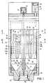
- the extrusion head of the exemplary embodiment according to FIGS. 1-5 has, in the usual way, a housing 10, within which a mandrel 12 coaxial therewith is arranged, which carries at its lower end a fitting 14 which has the annular channel 18 leading to the annular extrusion opening 16 limited on the inside.
- a nozzle core 19 is guided within the adapter 14 and, together with the nozzle ring 20 surrounding it, delimits the extrusion opening 16.
- the nozzle core is carried by a rod 22 which is guided within the mandrel 12 and is connected at its end remote from the extrusion opening 16 to the piston 23 of a hydraulic cylinder 24.
- the nozzle core 19 can be axially up and down to influence the width of the extrusion opening 16 are shifted. This is made possible in the usual way in that the opposing surfaces of the nozzle core 19 and the nozzle ring 20 surrounding it are designed to be conical.
- An annular piston 26 is arranged so that it can be moved axially back and forth within the housing 10.
- the annular piston 26 is connected at its end region facing away from the extrusion opening to the piston rod 21 of a piston 25 which is guided in a hydraulic cylinder 27.
- a plurality of piston-cylinder arrangements 25, 27 can be provided, of which only one is shown in the drawing. It is also possible to provide only one piston-cylinder arrangement, which would then be arranged in such a way that it acts on the annular piston 26 symmetrically.
- FIGS. 1 and 4 the annular piston assumes its upper end position, in which its end face 28 facing the extrusion opening 16 delimits a storage space 30 on the upper side, which is provided in the housing 10 in the region between the end face 28 of the annular piston 26 and the fitting piece 14.
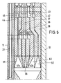
- Fig. 5 shows the lower end position of the annular piston 26, in which it is moved by the cylinder-piston assemblies 25, 27.
- the extrusion head is connected to six extruders, not shown in the drawing, from each of which a thermoplastic material or another material with the same properties is conveyed into the extrusion head with regard to processability.
- These extruders are connected in a suitable manner to channel systems arranged inside the annular piston 26. How the connection takes place in detail is not the subject of the invention. For example, there is a connection between the outlet openings of the extruders and the channel systems arranged inside the annular piston 26 are possible in the manner described in DE-OS 36 35 334. Other possibilities of connection are e.g. B. in DE-AS 21 61 356, in DE-PS 26 39 665 and in DE-PS 30 26 822 described.
- Each of the material flows coming from the extruders arrives inside the piston 26 in a feed channel 32, 33, 34, 35, 36, 37 which is approximately circular in cross section.
- These feed channels are arranged essentially parallel to the longitudinal axis of the extrusion head.
- the feed channels 32, 33, 34, 35 arranged on a radius of the annular piston open into annular distributor channels 42, 43, 44, 45 arranged coaxially to the longitudinal axis of the extrusion head and at radial distances from one another, which run in a common plane perpendicular to the longitudinal axis of the extrusion head .
- the feed channel 36 arranged on the same radius opens into an annular distributor channel 46 which rotates within the annular piston 36 in a plane perpendicular to the longitudinal axis of the extrusion head and which is located at a smaller distance from the free end 28 of the annular piston than the distributor channels 42, 43, 44 , 45.
- the feed channel 37 which is offset in relation to the other feed channels in the circumferential direction of the cross section of the extrusion head, continues into two connecting channels 37a, 37b, each of which opens into an annular distributor channel 47a, 47b.
- the annular distributor channels 47a, 47b are arranged in the same plane as the annular distributor channel 46.
- the annular piston 36 thus contains a total of seven annular distributor channels which are arranged for reasons of space from two planes which are axially spaced from one another.
- the distribution channels it is in the form of a closed line through the cross section preferably circular feed channels each formed material stream formed into a circular in cross-section material stream.
- Each of the distribution channels 42, 43, 44, 45, 46, 47a, 47b is followed by a ring channel 52, 53, 54, 55, 56, 57a, 57b, all ring channels with the exception of the ring channels 54, 55 at the front end 28 of the annular piston 26 open into the storage space 30.
- the ring channels 54 and 55 open into the collecting ring channel 50, so that the material flows flowing through the ring channels 54, 55 unite in the region of their openings into the collecting ring channel 50 to form a prelaminate which consists of two layers.
- the configuration described above, in which the two ring channels 54, 55 are followed by a common collecting ring channel 50, can, for. B.
- the two feed channels 34, 35 for feeding the two streams of material forming the prelaminate will be arranged offset in relation to one another in the circumferential direction by the seams forming in the streams of material in the circumferential direction to put something against each other.
- the partial flows of material flowing in the circumferential direction are indicated by arrows in FIGS. 2 and 3 of the drawing.
- the material flow supplied through the feed channel 37 is divided into two partial material flows, which are each fed through the connecting channels 37a, 37b to an annular distributor channel 47a, 47b, so that two material flows are created and consequently at least two layers are present in the end laminate, which consist of the same material and come from an extruder.
- All of the annular channels 52, 53, 57b, 56, 57a, 50 opening into the storage space 30 are provided with end sections 62, 63, 67b, 66, 67a, 60, which expand conically in the direction of flow of the plastic flowing through the individual channel systems, the partition walls located between the ring channels experience a corresponding reduction in their thickness in the flow direction. This serves to reduce the speed of the individual material flows in these end sections 62, 63, 67b, 66, 67a, 60.
- the individual material flows are already brought closer to one another as they flow through these conically widening end sections, so that they pass through the respective outlet 72, 73, 77b, 76, 77a, 70 at the end boundary 28 of the annular piston 26, essentially through the ends of the walls delimiting the individual ring channels are defined, unite within the storage space 30 to form the end laminate.
- the end laminate formation point is thus within the storage space 30, but in direct connection to the outputs 72, 73, 77b, 76, 77a, 70 of the ring channels or the end sections thereof at the end face of the annular piston 26, which is located under the laminate formation the action of the storage space 30 filling laminate moves up until it has reached the end position shown in FIGS. 1 and 4. It is generally not necessary to close the extrusion opening 16, since the resistance that the annular piston 26 with its drive means 25, 27 opposes to the laminate filling the storage space 30 is normally less than the flow resistance of the extrusion opening 16.
- the drawing shows (FIG. 4) that the individual material flows at the moment they pass through the exits 72, 73, 77b, 76, 77a, 70 at the free end 28 of the annular piston 26 the entire width, that is to say the radial extent, of the storage space 30 to complete.
- This has the consequence that at the moment of the laminate formation, that is to say the connection of the individual material streams to the end laminate, only a slight transverse movement of the individual material streams is required in order to come into contact with one another and thereby connect to the end laminate.
- the end sections 62, 63, 67b, 66, 67a, 60 of the ring channels 52, 53, 57b, 56, 57a, 50 are also designed to widen conically in the direction of flow such that in the plane, in which the outputs 72, 73, 77b, 76, 77a, 70 lie, that is to say in the exemplary embodiment in the plane of the end face of the annular piston 26, the radial extent of the individual end sections is proportional to the thickness of the individual layers which are directed onto the outputs 72, 73, 77b, 76, 77a, 70 decrease material flows and that form in the storage space 30 end laminate.
- These layers are indicated in Fig.
- the arrangement is such that the material flows passing the exits extend over almost the entire width of the storage space 30, so that no noticeable transverse movements of the layers 82, 83, 87b, 86, 87a, 80 forming Material flows are required to combine them into the lamiant.
- annular piston 26 it is also not necessary to design the free end of the annular piston 26 so that the ends of all the partition walls run in a parting plane perpendicular to the longitudinal axis of the extrusion head.
- conditions that result from the required mechanical strength of the annular piston and the individual parts of the same could also be taken into account, although the annular piston is guided with its outer and inner lateral surfaces against the housing 10 or the mandrel 12, so that the outer partition walls, which are subject to one side due to the pressure of the plastic flows carried in the outer duct system 32, 42, 52, 62 or inner duct system 34, 45, 55, 50, are supported on the housing 10 or on the mandrel 12.
- the extrusion head described above works in the usual way.
- the procedure is such that the extruders from which the material flows are conveyed into the extrusion head continue to run, that is to say are operated continuously, even during the emptying stroke.
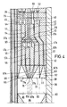
- FIG. 6 corresponds in terms of its construction and operation in all essential details to the embodiment of FIGS. 1-5, so that the same reference numerals are used for the same parts.
- the outputs 72, 73, 77b, 76, 77a, 70 of the channel systems located in the annular piston 26 have essentially the same radial extent.
- the embodiment according to FIG. 6 will be applicable if the differences in the thickness of the individual layers are not too great and / or the absolute speeds at which the material flows pass the exits are so small that speed differences are not very significant fall. 6 has the advantage of a somewhat simpler construction.
Landscapes
- Engineering & Computer Science (AREA)
- Mechanical Engineering (AREA)
- Manufacturing & Machinery (AREA)
- Blow-Moulding Or Thermoforming Of Plastics Or The Like (AREA)
- Processing And Handling Of Plastics And Other Materials For Molding In General (AREA)
- Extrusion Moulding Of Plastics Or The Like (AREA)
Claims (11)
- Procédé pour réaliser des corps creux en matière thermoplastique ayant une paroi lamifiée constituée de plusieurs couches liées entre elles et faites d'au moins deux matières plastiques de qualités différentes, en opérant au moyen de moules d'extrusion-soufflage, ce procédé consistant à produire d'abord des ébauches tubulaires dont la paroi comporte un nombre correspondant de couches, et à débiter ces ébauches de manière intermittente en utilisant une unité d'extrusion qui comporte au moins deux machines extrudeuses et une tête d'extrusion commune (10), pourvue d'une chambre d'accumulation annulaire (30) pour la matière lamifiée, d'un piston annulaire (26) pour assurer le vidage de la chambre d'accumulation (30), et d'un orifice d'extrusion (16), tous les courants de matière qui pénètrent dans la tête d'extrusion (10), et à partir desquels sont constituées les diverses couches de la matière lamifiée, étant guidés à travers le piston annulaire (26) et se transformant dans celui-ci pour y prendre une forme de section annulaire, caractérisé en ce que les courants de matière de section transversale annulaire qui sortent du piston annulaire (26), à l'endroit de son extrémité située du côté de l'orifice d'extrusion (16), s'écoulent séparément hors du piston annulaire dans la chambre d'accumulation (30) et se réunissent dans celle-ci pour y constituer la matière lamifiée.
- Procédé selon la revendication 1, caractérisé en ce que l'ensemble des courants de matière qui sortent du piston annulaire (26), à l'endroit de son extrémité située du côté de l'orifice d'extrusion (16) de la tête d'extrusion (10), présente en entrant dans la chambre d'accumulation (30) une étendue radiale qui correspond au moins à peu près à l'étendue radiale de la chambre d'accumulation (30).
- Procédé selon la revendication 1, caractérisé en ce que les courants de matière qui sortent séparément du piston annulaire (26), à l'endroit de son extrémité située du côté de l'orifice d'extrusion (16), pour se rejoindre dans la chambre d'accumulation (30) afin d'y constituer la matière lamifiée, sortent chacun du piston annulaire (26) avec une épaisseur qui est sensiblement proportionnelle à l'épaisseur de chacune des couches correspondantes de la matière lamifiée à réaliser en attente dans la chambre d'accumulation à partir de ces courants de matière.
- Procédé selon la revendication 3, caractérisé en ce que c'est seulement peu avant leur sortie du piston annulaire (26) que l'on donne aux courants de matière l'épaisseur qui est sensiblement proportionnelle à l'épaisseur de chacune des couches correspondantes de la matière lamifiée à réaliser en attente dans la chambre d'accumulation à partir de ces courants de matière.
- Procédé selon la revendication 1, caractérisé en ce que l'on opère sur au moins deux courants partiels de matière dès leur passage dans le piston annulaire (26), pour les réunir en constituant une ébauche lamifiée de section transversale annulaire, qui sort du piston annulaire (26) sous la forme d'un courant cohérent de matière.
- Dispositif pour réaliser des corps creux en matière thermoplastique ayant une paroi lamifiée constituée de plusieurs couches liées entre elles et faites d'au moins deux matières plastiques de qualités différentes, en opérant au moyen de moules d'extrusion-soufflage, ce dispositif comportant une unité d'extrusion pourvue au moins de deux machines extrudeuses et d'une tête d'extrusion commune (10) comportant une chambre d'accumulation (30) pour la matière lamifiée, un piston annulaire (26) pour assurer le vidage de la chambre d'accumulation (30), et un orifice annulaire d'extrusion (16) d'où sort l'ébauche réalisée au moment du vidage de la chambre d'accumulation (30), des systèmes de canaux internes (32, 42, 52; 33, 43, 53; 34, 44, 54, 50; 35, 45, 55, 50; 36, 46, 56; 37, 37a, 37b, 47a, 47b, 57a, 57b) étant prévus dans le piston annulaire (26), qui comprennent des canaux d'alimentation (32, 33, 34, 35, 36, 37) pour amener les matières plastiques et des canaux de distribution (42, 43, 44, 45, 46, 47a, 47b), dans lesquels le courant de matière correspondant subit une transformation pour prendre une forme de section transversale annulaire, et chaque canal de distribution étant raccordé à au moins un canal annulaire (52, 53, 54, 55, 56, 57a, 57b), qui débouche à l'endroit de l'extrémité du piston annulaire (26) située du côté de l'orifice d'extrusion (16), par une sortie (70, 72, 73, 76, 77a, 77b) qui se trouve sur la face frontale du piston annulaire, caractérisé en ce que les sorties (70, 72, 73, 76, 77a, 77b) qui se trouvent sur la face frontale du piston annulaire (26) débouchent dans la chambre d'accumulation (30) en étant séparées l'une de l'autre.
- Dispositif selon la revendication 6, caractérisé en ce que le nombre des canaux d'alimentation des systèmes de canaux correspond au nombre des sorties qui débouchent séparément dans la chambre d'accumulation.
- Dispositif selon la revendication 6, caractérisé en ce que l'étendue radiale de la zone dans laquelle sont disposées les sorties (70, 72, 73, 76, 77a, 77b) ménagées sur la face frontale du piston annulaire (26) située en regard de la chambre d'accumulation, correspond à peu près à la largeur radiale de la chambre d'accumulation(30).
- Dispositif selon la revendication 8, caractérisé en ce qu'au moins un certain nombre de canaux annulaires (52, 53, 50, 56, 57a, 57b) qui débouchent dans la chambre d'accumulation (30) présentent un évasement conique dans le sens de l'écoulement, en amont de chaque sortie correspondante (72, 73, 70, 76, 77a, 77b).
- Dispositif selon l'un des revendications 8 et 9, caractérisé en ce que la somme des largeurs radiales des parties terminales (62, 63, 67b, 66, 67a, 60) des canaux annulaires (52, 53, 57b, 56, 57a, 50) à l'endroit de leurs sorties (72, 73, 77b, 76, 77a, 70) est au moins à peu près égale à la largeur radiale de la chambre d'accumulation (30).
- Dispositif selon la revendication 6, caractérisé en ce que chacune des sorties séparées (70, 72, 73, 76, 77a, 77b), à l'endroit où elle débouche dans la chambre d'accumulation (30), présente une largeur qui est sensiblement proportionnelle à l'épaisseur de la couche correspondante réalisée dans la matière lamifiée à partir de chacun des courants de matière issus des sorties (70, 72, 73, 76, 77a, 77b) qui sont situées sur la face frontale du piston annulaire (26).
Priority Applications (1)
| Application Number | Priority Date | Filing Date | Title |
|---|---|---|---|
| AT89111570T ATE82188T1 (de) | 1988-07-04 | 1989-06-24 | Verfahren und vorrichtung zum herstellen von hohlkoerpern aus thermoplastischen kunstoffen. |
Applications Claiming Priority (2)
| Application Number | Priority Date | Filing Date | Title |
|---|---|---|---|
| DE3822524 | 1988-07-04 | ||
| DE3822524A DE3822524A1 (de) | 1988-07-04 | 1988-07-04 | Verfahren und vorrichtung zum herstellen von hohlkoerpern aus thermoplastischen kunststoffen |
Publications (2)
| Publication Number | Publication Date |
|---|---|
| EP0349872A1 EP0349872A1 (fr) | 1990-01-10 |
| EP0349872B1 true EP0349872B1 (fr) | 1992-11-11 |
Family
ID=6357883
Family Applications (1)
| Application Number | Title | Priority Date | Filing Date |
|---|---|---|---|
| EP89111570A Expired - Lifetime EP0349872B1 (fr) | 1988-07-04 | 1989-06-24 | Procédé et dispositif pour la fabrication de corps creux en matière thermoplastique |
Country Status (7)
| Country | Link |
|---|---|
| US (1) | US5004578A (fr) |
| EP (1) | EP0349872B1 (fr) |
| JP (1) | JP2824665B2 (fr) |
| AT (1) | ATE82188T1 (fr) |
| CA (1) | CA1320319C (fr) |
| DE (2) | DE3822524A1 (fr) |
| ES (1) | ES2035449T3 (fr) |
Families Citing this family (13)
| Publication number | Priority date | Publication date | Assignee | Title |
|---|---|---|---|---|
| DE3831836A1 (de) * | 1988-09-20 | 1990-03-22 | Kautex Maschinenbau Gmbh | Verfahren und vorrichtung zum herstellen von hohlkoerpern aus thermoplastischem kunststoff |
| DE3831837A1 (de) * | 1988-09-20 | 1990-03-22 | Kautex Maschinenbau Gmbh | Verfahren und vorrichtung zum herstellen von hohlkoerpern aus thermoplastischem kunststoff |
| US5202074A (en) * | 1989-12-26 | 1993-04-13 | The Dow Chemical Company | Method for producing injection molded multilayer articles |
| US5380479A (en) * | 1989-12-26 | 1995-01-10 | The Dow Chemical Company | Method and apparatus for producing multilayer plastic articles |
| BR9105780A (pt) * | 1990-06-01 | 1992-08-04 | Mauser Werke Gmbh | Cabecote de reservatorio para uma maquina de moldar por sopro |
| DE4020819A1 (de) * | 1990-06-29 | 1990-11-08 | Bock Stefan Dipl Ing Fh | Speicherkopf zur fertigung von ein- oder mehrschichtig schlauch-ueber-schlauch strukturierten vorformlingen aus thermoplasten |
| JP2694063B2 (ja) * | 1991-04-15 | 1997-12-24 | 株式会社日本製鋼所 | 多層パリソンの押出制御方法 |
| US5662842A (en) | 1994-07-18 | 1997-09-02 | Salflex Polymers Ltd. | Process for blow molding hollow objects with independent movement of mold halves |
| US6261400B1 (en) * | 1997-04-09 | 2001-07-17 | Spalding Sports Worldwide, Inc. | Method of manufacturing multi-layer game ball |
| US5776519A (en) * | 1997-06-06 | 1998-07-07 | Graham Engineering Corporation | Parison extrusion head with quick change die ring clamp assembly |
| US20060038310A1 (en) | 2004-07-29 | 2006-02-23 | Erik Lipson | Method and apparatus for forming extruded striped plastic products with variations in width of the stripes along the length of the products and for blow molding articles formed from such extruded parts |
| CN109352952B (zh) * | 2018-10-31 | 2021-03-16 | 徐州耐克盾机械制造有限公司 | 一种多层共挤吹塑机储料式模头 |
| CN109352951A (zh) * | 2018-10-31 | 2019-02-19 | 徐州耐克盾机械制造有限公司 | 一种多功能吹塑机模头 |
Family Cites Families (16)
| Publication number | Priority date | Publication date | Assignee | Title |
|---|---|---|---|---|
| DE1704791B2 (de) * | 1968-03-18 | 1976-07-29 | Kautex Werke Reinold Hagen Gmbh, 5300 Bonn-Holzlar | Vorrichtung zum herstellen von im querschnitt ringfoermigen koerpern aus thermoplastischem kunststoff |
| US3985490A (en) * | 1974-06-04 | 1976-10-12 | Mauser Kommanditgesellschaft | Apparatus for extruding a homogeneous tubular length of soft thermoplastic material |
| DE2617898C2 (de) * | 1976-04-23 | 1984-06-28 | Reiner Dipl.-Ing. 5205 St.Augustin Kader | Spritzkopf zum Herstellen eines schlauchförmigen Stranges aus thermoplastischem Kunststoff |
| US4120633A (en) * | 1976-06-09 | 1978-10-17 | Harald Feuerherm | Extrusion press head for the extrusion of tubular strands of plastic material |
| DE2639665C2 (de) * | 1976-09-03 | 1983-11-10 | Harald 5210 Troisdorf Feuerherm | Strangpreßkopf zum Herstellen eines hohlen Stranges aus thermoplastischem Kunststoff |
| DE2712911A1 (de) * | 1977-03-24 | 1978-09-28 | Mauser Kg | Spritzkopf zur herstellung eines schlauchfoermigen stranges aus thermoplastischem kunststoff |
| DE2712910A1 (de) * | 1977-03-24 | 1978-09-28 | Mauser Kg | Schlauchkopf |
| US4422838A (en) * | 1979-12-27 | 1983-12-27 | Ishikawajima-Harima Jukogyo Kabushiki Kaisha | Extrusion head for use in blow molding machine |
| US4297092A (en) * | 1980-06-30 | 1981-10-27 | Midland-Ross Corporation | Accumulator head used in the formation of a multi-layer parison |
| DE3026822C2 (de) * | 1980-07-16 | 1985-02-21 | Reiner Dipl.-Ing. 5205 St.Augustin Kader | Winkelspritzkopf zum Herstellen eines Schlauches |
| DE3305242A1 (de) * | 1983-02-16 | 1984-08-16 | Battenfeld-Fischer Blasformtechnik GmbH, 5204 Lohmar | Pinole fuer den dorn eines schlauchkopfes zur herstellung von schlauchabschnitten oder schlaeuchen aus thermoplastischem kunststoff |
| US4548569A (en) * | 1984-08-06 | 1985-10-22 | Somerset Technologies, Inc. | Accumulator head |
| DE3620144A1 (de) * | 1986-06-14 | 1987-12-17 | Bekum Maschf Gmbh | Speicherkopf fuer die herstellung mehrschichtiger co-extrudierter schlaeuche aus kunststoff |
| DE3623308A1 (de) * | 1986-07-11 | 1988-01-28 | Battenfeld Fischer Blasform | Strangpresskopf zur herstellung von verbundschlaeuchen aus unterschiedlichen thermoplastischen kunststoffmaterialien |
| DE3635334C3 (de) * | 1986-10-17 | 1997-04-03 | Guenter Richter | Vorrichtung zur diskontinuierlichen Herstellung mehrschichtiger, coextrudierter, schlauchartiger Vorformlinge aus thermoplastischem Kunststoff für das Blasformen |
| US4874305A (en) * | 1988-11-03 | 1989-10-17 | Somerset Technologies, Inc. | Accumulator extrusion head for producing striped parisons |
-
1988
- 1988-07-04 DE DE3822524A patent/DE3822524A1/de not_active Withdrawn
-
1989
- 1989-06-24 DE DE8989111570T patent/DE58902663D1/de not_active Expired - Lifetime
- 1989-06-24 ES ES198989111570T patent/ES2035449T3/es not_active Expired - Lifetime
- 1989-06-24 AT AT89111570T patent/ATE82188T1/de not_active IP Right Cessation
- 1989-06-24 EP EP89111570A patent/EP0349872B1/fr not_active Expired - Lifetime
- 1989-06-30 US US07/375,167 patent/US5004578A/en not_active Expired - Lifetime
- 1989-07-04 JP JP1172825A patent/JP2824665B2/ja not_active Expired - Lifetime
- 1989-07-04 CA CA000604740A patent/CA1320319C/fr not_active Expired - Fee Related
Also Published As
| Publication number | Publication date |
|---|---|
| ATE82188T1 (de) | 1992-11-15 |
| JP2824665B2 (ja) | 1998-11-11 |
| DE3822524A1 (de) | 1990-01-11 |
| CA1320319C (fr) | 1993-07-20 |
| EP0349872A1 (fr) | 1990-01-10 |
| DE58902663D1 (de) | 1992-12-17 |
| ES2035449T3 (es) | 1993-04-16 |
| US5004578A (en) | 1991-04-02 |
| JPH0270405A (ja) | 1990-03-09 |
Similar Documents
| Publication | Publication Date | Title |
|---|---|---|
| DE2733913C2 (de) | Verfahren und Vorrichtung zum Herstellen eines mehrschichtigen Spritzgußkörpers aus thermoplastischen Kunstharzen | |
| EP0326584B1 (fr) | Procede et dispositif de production de corps creux et volumineux en plastique a parois stratifiees | |
| EP1183145B1 (fr) | Dispositif de realisation de recipients a au moins deux compartiments, par extrusion-soufflage | |
| EP0995579B1 (fr) | Procédé de production en continu d'un tube composite avec manchon, et appareil pour la mise en oeuvre du procédé | |
| EP0361187B1 (fr) | Procédé et dispositif de fabrication de corps creux en matière thermoplastique | |
| EP0249866B1 (fr) | Tête d'accumulation pour la fabrication de tuyaux souples coextrudés multicouches en matière plastique | |
| EP0349872B1 (fr) | Procédé et dispositif pour la fabrication de corps creux en matière thermoplastique | |
| DE2100192A1 (de) | Verfahren und Vorrichtung zum Herstellen von schlauchartigen Formungen aus thermoplastischem Kunststoff | |
| DE102013105749B4 (de) | Extrusionsschlauchkopf für diskontinuierliches Schäumen | |
| EP0465889B1 (fr) | Dispositif pour la fabrication de corps creux en matière thermoplastique | |
| EP0274095B1 (fr) | Tête de co-extrusion | |
| DE3439285A1 (de) | Verfahren und vorrichtung zum herstellen eines hohlen kunststoffkoerpers | |
| DE3902270A1 (de) | Verfahren und vorrichtung zur diskontinuierlichen herstellung mehrschichtiger, coextrudierter, schlauchartiger vorformlinge aus thermoplastischem kunststoff | |
| DE1261657B (de) | Spritzkopf zum Herstellen von schlauchfoermigen Straengen | |
| DE3044535A1 (de) | Verfahren und vorrichtung zur herstellung mehrschichtiger kunststoffprofile, insbesondere kunststoffrohre | |
| EP0093894A1 (fr) | Outils d'extrusion | |
| DE4225011A1 (de) | Vorrichtung zum Herstellen eines Metall-Kunststoff-Verbundrohres | |
| EP0923445A1 (fr) | Conteneur du type tonneau en matiere plastique et procede et dispositif pour sa fabrication | |
| EP0407847B1 (fr) | Procédé et dispositif pour produire des corps creux en matière thermoplastique | |
| DE19545441B4 (de) | Vorrichtung zur Herstellung eines schlauchartigen Vorformlings sowie aus dem Vorformling hergestelltes Formteil | |
| EP1388406B1 (fr) | Procédé et dispositif pour la fabrication par soufflage de corps creux en matière thermoplastique | |
| EP1334815B1 (fr) | Buse annulaire à faible coefficient de friction pour l'extrusion de tubes en plastique | |
| DE69217025T2 (de) | Düse zur Herstellung coextrudierter Artikel | |
| DE102021118705A1 (de) | Vorrichtung und Verfahren für die biaxiale Kunststoff-Extrusion | |
| DE1179356B (de) | Vorrichtung zum Herstellen von Schlaeuchen aus thermoplastischem Material, insbesondere thermoplastischen Kunststoffen |
Legal Events
| Date | Code | Title | Description |
|---|---|---|---|
| PUAI | Public reference made under article 153(3) epc to a published international application that has entered the european phase |
Free format text: ORIGINAL CODE: 0009012 |
|
| AK | Designated contracting states |
Kind code of ref document: A1 Designated state(s): AT BE CH DE ES FR GB GR IT LI LU NL SE |
|
| 17P | Request for examination filed |
Effective date: 19900626 |
|
| 17Q | First examination report despatched |
Effective date: 19910930 |
|
| ITF | It: translation for a ep patent filed | ||
| GRAA | (expected) grant |
Free format text: ORIGINAL CODE: 0009210 |
|
| AK | Designated contracting states |
Kind code of ref document: B1 Designated state(s): AT BE CH DE ES FR GB GR IT LI LU NL SE |
|
| PG25 | Lapsed in a contracting state [announced via postgrant information from national office to epo] |
Ref country code: SE Effective date: 19921111 Ref country code: NL Effective date: 19921111 Ref country code: GR Free format text: LAPSE BECAUSE OF FAILURE TO SUBMIT A TRANSLATION OF THE DESCRIPTION OR TO PAY THE FEE WITHIN THE PRESCRIBED TIME-LIMIT Effective date: 19921111 Ref country code: BE Effective date: 19921111 |
|
| REF | Corresponds to: |
Ref document number: 82188 Country of ref document: AT Date of ref document: 19921115 Kind code of ref document: T |
|
| GBT | Gb: translation of ep patent filed (gb section 77(6)(a)/1977) | ||
| REF | Corresponds to: |
Ref document number: 58902663 Country of ref document: DE Date of ref document: 19921217 |
|
| ET | Fr: translation filed | ||
| NLV1 | Nl: lapsed or annulled due to failure to fulfill the requirements of art. 29p and 29m of the patents act | ||
| REG | Reference to a national code |
Ref country code: ES Ref legal event code: FG2A Ref document number: 2035449 Country of ref document: ES Kind code of ref document: T3 |
|
| PG25 | Lapsed in a contracting state [announced via postgrant information from national office to epo] |
Ref country code: LU Free format text: LAPSE BECAUSE OF NON-PAYMENT OF DUE FEES Effective date: 19930630 Ref country code: LI Effective date: 19930630 Ref country code: CH Effective date: 19930630 |
|
| PLBI | Opposition filed |
Free format text: ORIGINAL CODE: 0009260 |
|
| 26 | Opposition filed |
Opponent name: BATTENFELD FISCHER BLASFORMTECHNIK GMBH Effective date: 19930810 |
|
| REG | Reference to a national code |
Ref country code: CH Ref legal event code: PL |
|
| PLBN | Opposition rejected |
Free format text: ORIGINAL CODE: 0009273 |
|
| STAA | Information on the status of an ep patent application or granted ep patent |
Free format text: STATUS: OPPOSITION REJECTED |
|
| 27O | Opposition rejected |
Effective date: 19950221 |
|
| PGFP | Annual fee paid to national office [announced via postgrant information from national office to epo] |
Ref country code: ES Payment date: 20010528 Year of fee payment: 13 |
|
| PGFP | Annual fee paid to national office [announced via postgrant information from national office to epo] |
Ref country code: GB Payment date: 20010620 Year of fee payment: 13 |
|
| PGFP | Annual fee paid to national office [announced via postgrant information from national office to epo] |
Ref country code: FR Payment date: 20010621 Year of fee payment: 13 |
|
| PGFP | Annual fee paid to national office [announced via postgrant information from national office to epo] |
Ref country code: AT Payment date: 20010625 Year of fee payment: 13 |
|
| PGFP | Annual fee paid to national office [announced via postgrant information from national office to epo] |
Ref country code: DE Payment date: 20010822 Year of fee payment: 13 |
|
| REG | Reference to a national code |
Ref country code: GB Ref legal event code: IF02 |
|
| PG25 | Lapsed in a contracting state [announced via postgrant information from national office to epo] |
Ref country code: GB Free format text: LAPSE BECAUSE OF NON-PAYMENT OF DUE FEES Effective date: 20020624 Ref country code: AT Free format text: LAPSE BECAUSE OF NON-PAYMENT OF DUE FEES Effective date: 20020624 |
|
| PG25 | Lapsed in a contracting state [announced via postgrant information from national office to epo] |
Ref country code: ES Free format text: LAPSE BECAUSE OF NON-PAYMENT OF DUE FEES Effective date: 20020625 |
|
| PG25 | Lapsed in a contracting state [announced via postgrant information from national office to epo] |
Ref country code: DE Free format text: LAPSE BECAUSE OF NON-PAYMENT OF DUE FEES Effective date: 20030101 |
|
| GBPC | Gb: european patent ceased through non-payment of renewal fee |
Effective date: 20020624 |
|
| PG25 | Lapsed in a contracting state [announced via postgrant information from national office to epo] |
Ref country code: FR Free format text: LAPSE BECAUSE OF NON-PAYMENT OF DUE FEES Effective date: 20030228 |
|
| REG | Reference to a national code |
Ref country code: FR Ref legal event code: ST |
|
| REG | Reference to a national code |
Ref country code: ES Ref legal event code: FD2A Effective date: 20030711 |
|
| PG25 | Lapsed in a contracting state [announced via postgrant information from national office to epo] |
Ref country code: IT Free format text: LAPSE BECAUSE OF NON-PAYMENT OF DUE FEES;WARNING: LAPSES OF ITALIAN PATENTS WITH EFFECTIVE DATE BEFORE 2007 MAY HAVE OCCURRED AT ANY TIME BEFORE 2007. THE CORRECT EFFECTIVE DATE MAY BE DIFFERENT FROM THE ONE RECORDED. Effective date: 20050624 |