EP0349847A2 - Verfahren und Vorrichtung für die Bilddatenkomprimierung - Google Patents
Verfahren und Vorrichtung für die Bilddatenkomprimierung Download PDFInfo
- Publication number
- EP0349847A2 EP0349847A2 EP89111416A EP89111416A EP0349847A2 EP 0349847 A2 EP0349847 A2 EP 0349847A2 EP 89111416 A EP89111416 A EP 89111416A EP 89111416 A EP89111416 A EP 89111416A EP 0349847 A2 EP0349847 A2 EP 0349847A2
- Authority
- EP
- European Patent Office
- Prior art keywords
- image data
- data
- coefficients
- code
- pixel block
- Prior art date
- Legal status (The legal status is an assumption and is not a legal conclusion. Google has not performed a legal analysis and makes no representation as to the accuracy of the status listed.)
- Granted
Links
Images


Classifications
-
- H—ELECTRICITY
- H04—ELECTRIC COMMUNICATION TECHNIQUE
- H04N—PICTORIAL COMMUNICATION, e.g. TELEVISION
- H04N19/00—Methods or arrangements for coding, decoding, compressing or decompressing digital video signals
- H04N19/10—Methods or arrangements for coding, decoding, compressing or decompressing digital video signals using adaptive coding
- H04N19/134—Methods or arrangements for coding, decoding, compressing or decompressing digital video signals using adaptive coding characterised by the element, parameter or criterion affecting or controlling the adaptive coding
- H04N19/154—Measured or subjectively estimated visual quality after decoding, e.g. measurement of distortion
-
- H—ELECTRICITY
- H04—ELECTRIC COMMUNICATION TECHNIQUE
- H04N—PICTORIAL COMMUNICATION, e.g. TELEVISION
- H04N19/00—Methods or arrangements for coding, decoding, compressing or decompressing digital video signals
- H04N19/10—Methods or arrangements for coding, decoding, compressing or decompressing digital video signals using adaptive coding
- H04N19/102—Methods or arrangements for coding, decoding, compressing or decompressing digital video signals using adaptive coding characterised by the element, parameter or selection affected or controlled by the adaptive coding
- H04N19/124—Quantisation
-
- H—ELECTRICITY
- H04—ELECTRIC COMMUNICATION TECHNIQUE
- H04N—PICTORIAL COMMUNICATION, e.g. TELEVISION
- H04N19/00—Methods or arrangements for coding, decoding, compressing or decompressing digital video signals
- H04N19/10—Methods or arrangements for coding, decoding, compressing or decompressing digital video signals using adaptive coding
- H04N19/102—Methods or arrangements for coding, decoding, compressing or decompressing digital video signals using adaptive coding characterised by the element, parameter or selection affected or controlled by the adaptive coding
- H04N19/132—Sampling, masking or truncation of coding units, e.g. adaptive resampling, frame skipping, frame interpolation or high-frequency transform coefficient masking
-
- H—ELECTRICITY
- H04—ELECTRIC COMMUNICATION TECHNIQUE
- H04N—PICTORIAL COMMUNICATION, e.g. TELEVISION
- H04N19/00—Methods or arrangements for coding, decoding, compressing or decompressing digital video signals
- H04N19/60—Methods or arrangements for coding, decoding, compressing or decompressing digital video signals using transform coding
Definitions
- the present invention relates to a method of and an apparatus for compressing image data having graduation with respect to every pixel block for reducing the amount of data of image information
- image data is obtained for every pixel, which is a constant small area, by reading an original image.
- the image data employed in the field of printing are usually larger in amount than those employed in television, and the amount of the information thereof reaches several to tens of mega bites for each image.
- Such a large amount of image data would require enourous memory capacity if they were stored in a data base as they were; thus the cost for data transmission would increase greatly
- the data compression methods in the art suffer from a trade-off between a compression rate (or compressibility) and quality of a reproduced image produced by the compressed image data. If the compression rate is increased, the quality of the image is lowered. On the other hand, the compression rate is decreased in order to raise the quality of the image. This is not a big issue for the image data employed in a television because the quality of the images of the television is relatively low compared with that employed in the field of printing.
- the data compression methods in the art have another issue concerning repetition of data compression and data restoration. If the data compression is execused by high compression rate, the image quality of a restored image obtained by restoring the compressed data is lowered as compared with the original image. Thus, when the data compression and restoration are repeated several times, the image quality is gradually lowered.
- the present invention is directed to a method of and an apparatus for compressing image data depicting an image with respect to each pixel block including a plurality of pixels, the method comprising the steps of: (a) executing an orthogonal transformation operation on the image data with respect to each pixel block, to thereby obtain a coefficient table including coefficients of a series of orthogonal functions of the image data for each pixel bolck, (b) preparing a plurality of code tables, each of the plurality of code tables validating a part of the coefficients of the coefficient table, (c) obtaining valid coefficients of the coefficient table with respect to each code table, the valid coefficients being validated by each code table, (d) selecting a most relevant code table most relevant to the coefficient table within the plurality of code tables on the basis of the valid coefficients, and (e) collecting the valid coefficients validated by the relevant code table, to thereby form compressed data comprising the valid coefficients for each pixel bolck.
- the step (d) comprises the steps of: (d-1) computing representative values for respective code tables, each of the representative values being correlated with a sum of absolute values of the valid coefficients, and (d-2) comparing the representative values with each other, thereby selecting the most relevant code table.
- the plurality of code tables are classified into a plurality of groups, and the step (c) comprises the steps of: (c-1) preparing a statistical value indicative of a standard deviation of image data for each pixel block, (c-2) selecting one of the plurality of groups for each pixel block in response to the statistical value, and (c-3) computing the valid coefficients only for code tables included in the selected group.
- the present invention is also directed to a method of and an apparatus for compressing image data depicting an image with respect to each pixel block including a plurality of pixels, the method comprising the steps of: (a) preparing a statistic value indicative of a standard deviation of the image data within each pixel block, (b) selecting one of prescribed procedures of data compression in response to the statistic value, (c) executing data compression on the image data according to a selected procedure, to thereby obtain first compressed data representing the image, (d) storing the first compressed data with identification data specifying the selected procedure, (e) executing data restoration on the first compressed data, to thereby obtain restored image data depicting the image and including the identification data therein, (f) identifying the selected procedure by means of the identification data included in the restored image data, and (g) executing data compression on the restored image data according to the selected procedure identified in the step (f), to thereby obtain second compressed data representing the image.
- the restored data includes a plurality of components each of which is formed as digital data and the identification data is expressed by a least significant digit of a component of the restored data, the component representing a part of the image at a prescribed position in one pixel block.
- each of the prescribed procedure comprises the steps of: (1) executing an orthogonal transformation operation on the image data with respect to each pixel block, to thereby obtain a coefficient table including coefficients of a series of orthogonal functions indicative of the image data for each pixel block, (2) preparing a plurality of code tables peculiar to each of the prescribed procedures, each of the plurality of code tables validating a part of the coefficients of the coefficient table, (3) obtaining valid coefficients of the coefficient table with respect to each code table, the valid coefficients being validated by each code table, (4) selecting a most relevant code table most relevant to the coefficient table within the plurality of code tables on the basis of the valid coefficients, and (5) collecting the valid coefficients validated by the relevant code table, to thereby form compressed data comprising the valid coefficients for each pixel block.
- each of the plurality of code tables for a same procedure may validate a same number of the coefficients.
- coefficients of the coefficient table may be expressed by means of digital data, and repective code elements in each of the plurality of code tables may be designate respective numbers of effective digits for respective valid coefficients.
- the restored image data including the identification data enables to execute data compression on the restored image data by the same sequence which was emplyed to obtain the first compressed data. Accordingly, the deterioration of the image quality is suppressed even if data compression and restoration are repeared several times.
- the total amount of the restored image data is further reduced because the identification data does not exist independently.
- an object of the present invention is to increase the compression rate (or compressibility) without lowering the image quality too much.
- Another object of the present invention is to suppress the deterioration of the image qaulity when the data compression and restoration are repeated several times.
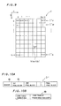
- Fig. 1 is a conceptual diagram showing pixel blocks in an image 1.
- the image 1 is composed of XxY pixels P, and is divided into VxH pixel blocks B vh each having a plurality of pixels.
- Fig. 2 is a conceptaul diagram showing the structure of one pixel block B vh .
- the pixel block B vh is composed of MxN pixels P ij and image data f ij is obtained for every pixel.
- the pixel block B vh is composed of 8x8 pixels in the example shown in Fig. 2, the same may be composed of 4x4 pixels or 16x16 pixels.
- the image data are first subjected to orthogonal transformation with respect to every pixel block B vh in the image 1.
- orthogonal transformation Several types of the orthogonal transformation can be applied such as discrete Fourier transformation, Hadamard's transformation and the like.
- a Discrete Cosine Transformation (hereinafter referred to as "DCT") is employed.
- DCT Discrete Cosine Transformation
- the following equation expresses a coefficient F mn associated with a specific function in a series of transformation functions for DCT. m and n have values generally within ranges of zero to (M - 1) and zero to (N - 1), respectively.
- Fig. 3 is an explanatory diagram showing the image data f ij within one pixel block and the transformation coefficient F mn obtained through the expression (1).
- Fig. 3 (a-1) and Fig. 3(b-2) show tables FT which have the transformation coefficients F mn .
- a tranformation coefficient F00 shows an average value (hereinafter referred to as "direct current component") of the image data f ij
- remaining tranformation coefficients F mn hereinafter referred to as "alternate current components” show distribution of the image data f ij .
- Each of the tranformation coefficients F mn is expressed by means fo binary data of 8 bit, for example. However, the values of the coefficients are shown in decimal notation in Fig. 3, for convenience of illustration.
- the transformation coefficients F mn show the following character. As well as positions (m,n) at which the transformation coefficients F mn are nonzero, the values of the coefficients F mn are considerably varied in response to the distribution of the image data f ij . Those of the transformation coefficients F mn having large absolute values sprecifically represent the distribution of the original image data f ij , and the number of those tranformation coefficients F mn having large absolute values is increased in response to spatial uneveness of the image data f ij .
- Fig. 4 is an explanatory diagram showing a code table.
- This code table CT only a part of coordinates (m,n) are supplied with an effective bit number I mn .
- the effective bit number I mn indicates that the transformation coefficient F mn in the position (m,n) is validated by the table CT.
- the effective bit number I mn further indicates the maximum bit number for expressing the transformation coefficient F mn in binary system.
- symbol "-" indicates that the effective bit number is zero.
- All of the effective bit numbers I mn may be of the same value (8 bits, for example).
- the compression rate is raised by employing appropriate values (such as 8 bits or 3 bits, for example) which are smaller than the bit number (8 bits) of the original transformation coefficients F mn , and which are varied with the coordinates (m,n). Even if a transformation coefficient F mn has a value larger than the maximum effective value F max , its value is limited to the maximum effective value F max by the effective bit number I mn .
- the effective bit numbers I mn are empirically determined to avoid such situation as much as possible and even if the transformation coefficient F mn is limited to the maximum effective value F max , influence thereof can be neglected.
- a plurality of the code tables CT are prepared in advance of the data compression.
- the respective code tables CT have different patterns and values of the effective bit numbers I mn from each other.
- the patterns of the effective bit numbers I mn are empirically determined in order to reproduce an image of higher image quality with a smaller number of the transformation coefficients.
- the coefficient tables FT like those shown in Fig. 3 are first prepared for typical images such as a human figure, a landsape, a still life and the like. Then, by comparing the distribution of the coefficients in those coefficient tables FT with each other, the code tables are defined so as to represent major types of the distribution of the coefficients frequently seen in those coefficient tables.
- an optium code table (or a relevant code table) is selected for each coefficient table FT from the plurality of code tables CT.
- the sum S F of the effective transformation coefficients F mn (hereinafter simply referred to as "effective sum") is obtained in accordance with the following expression:
- the effective sum S F is obtained for each code table CT with respect to one coefficient table FT.
- the code table CT having the maximun effective sum is selected as the optium one to the coefficient table FT.
- the reliability of the selection of the optium code table as a funcion of the effective sum S F is further improved if the same number N c of the transformation coefficients F mn (hereinafter refered to as "effective component numbers") are validated by any of the respective code tables CT.
- the optium code table is identified by a table number defined for each code table CT.
- Compressed image data are produced on the basis of an average value of the original image data f ij , the table number of the optium code table CT and the values of the transformation coefficients F mn validated by the optium code talbe CT.
- the effective component number N c is far smaller than the total number MxN of the transformation coefficients F mn within a coefficient table and the value of each transformation coefficient F mn is expressed by a smaller effective bit number I mn , whereby the compression rate is quite increased.
- the compressed image data can be encoded by well-known Huffman codes or the like, in order to further increase the compression rate.
- the code tables CT are classified into a plurality of groups in response to characteristics of the image in order to still further improve the compression rate.
- the code tables CT are classified into a plurality of compression groups (code table groups) in respone to a standard deviation ⁇ of the image data f ij obtained for every pixel block B vh as follows: ⁇ ⁇ ⁇ 1: compression group g1 including code tables CT11 to CT 1L ⁇ 1 ⁇ ⁇ ⁇ ⁇ 2: compression group g2 including code tables CT21 to CT 2L ⁇ 2 ⁇ ⁇ ⁇ ⁇ 3: compression group g3 including code tables CT31 to CT 3L ⁇ 3 ⁇ ⁇ : compression group g4 including code tables CT41 to CT 4L (where ⁇ 1, ⁇ 2 and ⁇ 3 represent prescribed threshold values) Number L of the code tables may be varied with the compression groups g1 to g4.
- Fig. 5 illustrates distribution G of frequency A of the standard deviation ⁇ in an overall image 1. Referring to Fig. 5, the
- the first threshold value ⁇ 1 is determinerd such that the image in the pixel block is fairly even when the standard deviation ⁇ is less than the same.
- the image quality is not so much lowered even if a code table having a small value of the effective component number N c is employed for the data compression. Since the frequency A of a pixel block having smaller standard deviation ⁇ is generally higher as understood from Fig. 5, the compression rate is much improved by treating all of such pixel blocks with the code tables having a small effective component number N c .
- the compression rate would be decresed if all of such pixel blocks were processed with a code table having a large effective component number N c .
- the third threshold value ⁇ 3 is employed for further classification of the code tables.
- the effective component numbers of the code tables are constant within the respective compression groups.
- N c1 0, the compressed image data of a pixel block B vh belonging to the compression group g1 is expressed only by the average of the pixel data f ij , that is, only by the direct current component F00.
- the threshoid values ⁇ 1 to ⁇ 3 and the code tables CT 1k to CT 4k classified into the compression groups g1 to g4 are prepared.
- One of the compression groups g1 to g4 is selected in response to the standard deviation ⁇ of the block B vh , and the optium code table is selected from code tables included in the selected compression group.
- Restored image data f ij in a pixel block are obtained by executing Inverse Discreet Cosine Transformation (or IDCT) on the transformation coefficients F mn of compressed image data.
- IDCT Inverse Discreet Cosine Transformation
- IDCT is expressed as follows:
- the restored image data is so formed as to indicate which one of the compression groups g1 to g4 is employed for producing the compressed image data.
- Such information indicating the compression group is hereinafter referred to as "group information”.
- the code table number has a function of representing the group information, as hereinafter described.
- the group information is integrated into the restored image data f ij by using the least significant digits of the restored image data at prescribed pixel positions within a pixel block, for example.
- the group information can be expressed by two bits.
- two image data f11 and f33 are selected and their values are adjusted as follows to record the group information: compression group g1 : both of f11 and f33 are made even compression group g2 : f11 is made odd and f33 is made even compression group g3 : f11 is made even and f33 is made odd compression group g4 : both of f11 and f33 are made odd
- the bit-AND operator & expresses operation of obtaining logical product for each bit of binary numbers.
- the respective bits forming the group information N g are not restricted to those of the image data f11 and f33, but the least significant bits at two arbitrary pixel positions can be employed.
- the group information N g is expressed in a 2-bit binary number in this embodiment because of four compression groups, the bit number may be increased if more compression groups are employed.
- the restored image data are so formed as to include the group information, whereby the restored image data can be identified as being in the same compression group as the previous one in which the original image data before compression were included.
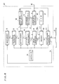
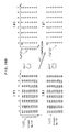
- FIG. 6 is a schematic block diagram showing the structure of an image data compressor emboding the present invention.
- an image data compressor AP comprises an image memory 5, a block read controller 6, a buffer memory 7, a two-dimentional DCT transformer 8, a linear quantizer 9, an encoder 10, a recording controller 11, a group-information read controller 12, a standard deviation calculator 14, a group information controller 15, a ROM 17 and a controller 13.
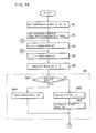
- the operation of the image data compressor AP will be described along flow charts shown in Figs. 7A and 7B.
- Step S1 the threshold values ⁇ 1 to ⁇ 3 of the standard deviation are inputted through a parameter input terminal 16 provided in the exterior of the data compressor AP, and set in the group informaiton controller 15.
- Steps S2 to S4 and S11 to S13 are adapted to sequentially select pixel blocks B vh to be processed.
- the block read controller 6 reads image data f11 within one pixel block B vh , and stores the same in the buffer memory 7.
- a step S6 is adapted to determine the group information N g .
- a decision is made as to whether or not the image data f ij are those of a restored image. If the image data f ij are those of a restored image, the image data f ij has data indicating that they are restored image data, in a header portion of a data file of the image data f ij , for example. The aforementioned decision is made in accordance with presence/absence of such data.
- steps S62 and S63 are carried out.
- the image data f ij are supplied from the buffer memory 7 to the standard deviation calculator 14, which in turn calculates the standard deviation ⁇ .
- the standard deviation ⁇ is supplied from the calculator 14 to the group information controller 15, which in turn determine the group information N g , That is, the group information controller 15 compares the standard deviation ⁇ with the threshold values ⁇ 1 to ⁇ 3, to determine which one of the compression groups g1 to g4 the pixel block belongs to. Then the controller 15 determines the group information N g by the expressions (10a) to (10d).
- a step S64 is carried out.
- the group information N g is synthesized by respective least significant bits e110 and e330 of image data f11 and f33 at two pixel positions, as shown by the expression (9).
- the image data f11 and f33 are read out from the buffer memory 7 in the group-information read controller 12.
- the read controller 12 synthesizes the group information N g through the image data f11 and f33, and supplies the same to the group information controller 15.
- the controller 15 holds the group information N g and performs no operation of determining the group information N g on the basis of the standard deviation ⁇ .
- the image data f ij are transmitted from the buffer memory 7 to the two-dimentional DCT transformer to be subjected to DCT at a step S7.
- the transformation coefficients F mn are linearly quantized.
- linear quantization means proccessing of dividing a transformation coefficient F mn by a predescribed value ⁇ ("quantum width") and making the value F mn / ⁇ to be integral when the values F mn / ⁇ includes decimal part.
- the value of the quantum width ⁇ may be fixed, or may be varied with the standard deviation ⁇ . Such linear quantization may not be performed, as hereinafter described.
- an optimum code table is selected with respect to a coefficient table FT* having the lineary quantized transformation coefficients F mn *.
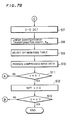
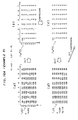
- Fig. 8 is a flow chart showing the procedure of selecting the optimum code table carried out by the encoder 10 at the step S9. Referring to Fig. 8, meaning of each symbol is as follows: max: parameter for obtaining maximum value of effective sum S F Max: parameter representing a code table number of a code table having the maximum effective sum S F l: parameter representing a code table number L: number of the code tables c: parameter representing a serial number of a effective current component N c : number of the effective alternate current components
- Step S21 the compression group of the pixel block under process is identified as a function of the compressing group information N g .
- Steps S22 to S30 are adapted to select that code table within L pieces of code tables of the compression group, which code table has the maximum effective sum S F (see expression (2)).
- a subtable T shown in Fig. 9, which is stored in the ROM 17, is employed.
- the subtable T specifies coordinate values (m lc , n lc ) of the coordinate positions in which the effective bit numbers I mn are nonzero.
- the subscript g of the code tables CT g1 to CT gL represent the compression group g i .
- the coordinates (m lc , n lc ) are sequentially called from the subtable T, and absolute values of the transformation coefficients F mn * of the transformation coefficient table FT* at the coordinates (m lc , n lc ) are added up at the step S24.
- the code table having the maximum effecitve sum S F is selected as the optimum code table.
- the effective transformation coefficients F mn * of the coefficient table FT* are specified by the optimum code table and are expressed in the effective bit numbers I mn (six bits, for example), while the other transformation coeffcients F mn * are neglected.
- the table number Max of the optimum code table and the transformation coefficients F mn * specified as effective by the optimum code table are transformed into a Huffman code train, to form compressed image data (steps S31 and S10 ).
- the average value of the original image data f ij may be simultaneously Huffman-coded at this time, while only the average value may be encoded by a method such as the so-called predictive encoding, independently of the step S31.
- Compressed image data (encoded data) D f thus obtained are transmitted to the data recording controller 11 from the encoder 10, and further outputted to the image memory 5 or a transmission path for an external circuit (not shown).
- a selection command for this output is inputted in the parameter input terminal 16 by an operater in advance of the compression of the image data, and initialized in the data recording controller 11.
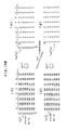
- Figs. 10A and 10B are conceptual diagrams showing the file structure of the encoded compressed image data D f .
- a header 18 of Fig. 10A includes the threshold values ⁇ 1, ⁇ 2 and ⁇ 3 etc., and the code trains of respective pixel blocks are arranged following the header 18.
- Fig. 10B is the internal structure in a code train 19 of each pixel block, which is formed of the table number Max of the optimum code table and the code train of the transformation coefficients F mn * specified as effective by the optimum code table.
- FIG. 11 is a schematic block diagram showing a restoration apparatus for restoring the encoded compressed image data D f .
- This restoraiton apparatus IAP comprises an image memory 20, a read controller 22, a buffer memory 23, a decoder 24, a ROM 25, an inverse quantizer 26, a two-dimentional IDCT Transformer 27, a group information recoder 28 and a recording controller 29.
- the compressed image data D f are read out from the image memory 23 or a transmission path 21 by the read controller 22, and supplied to the buffer memoy 23 and further transmitted to the decoder 24.
- the ROM 25 stores a code table identical to that employed for the compression of the image data, a Huffman code table for decording the Huffman code train, and the like.
- the compressed image data D f are decoded into the transformation coefficients F mn * by the decoder 24.
- the transformation coefficients F mn thus obtained are inverse-converted by the two-dimentional IDCT Transformer 27, whereby the image data ff ij of each pixel within the pixel block are obtained.
- the group information recoder 28 records the group information in the image data ff ij .
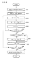
- Fig. 12 is a flow chart showing the recording procedure.
- the group information recoder 28 reads out the code table number Max within the compressed image data D f from the buffer memory 23.
- the group information N g is determined from the code table number Max.
- steps S33a to S33c and S34a to S34d the image data ff11 (f11) and ff33 (f33) are made odd/even.
- the steps S34a to S34d are carried out through the expressions (5) and (8).
- the image data f ij in which the group information N g is recorded are stored in the image memory 20 by the recording controller 28.
- Image data f ij for the overall image can be obtained by performing the restoration processing operation on all of the pixel blocks.
- the group information N g is read out from the least significant bits of two image data f11 and f33. Data compression is performed according to the compression group identified by the group information N g . Firstly, an example 1 will be described in which the linear quantization of F mn is not performed.
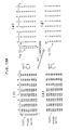
- Figs. 13A and 13B are explanatory diagrams showing image data f ij and transformation coefficients F mn in a first example of repeating compression and restoration.
- the transformation coefficients F mn are not subjected to linear quantization. Therefore, the transformation coefficients F mn of decimal values obtained by DCT are not made to be integers but directly preserved as the compressed image data D t and restored therefrom.
- Figs. 13A and 13B only integral parts of the transformtion coefficients F mn are shown for convenience of illustration.
- the image data f ij (k) are regularly preserved and restored in integral values.
- the image data f ij (0) of the original are DC transformed to the transformation coefficients F mn 0(1) of Fig. 13A(b).
- These transformation coefficients F mn 0(1) are not yet subjected to the selection of effective alternate current components by a code table, but have 19 alternate current components.
- transformation coefficients F mn (1) of Fig. 13A(c) are obtained as the result of the selection of the effective alternate current components by the code table.
- These transformation coefficients F mn (1) include six effecitve alternate current components F01, F02, F10, F11, F13 and F14.
- the restored image data F ij (1) of Fig. 13A(d) are obtained by IDCT of the transformation coefficients F mn (1).
- the threshold value ⁇ 1 is set at 4.0 and the threshold values ⁇ 2 and ⁇ 3 are set to be at least 5.0. Since the standard deviation ⁇ of the image data f ij (0) of the original is 4.862 as shown in Fig. 13A(a), the image data f ij (0) belong to the compression group g2.
- the image data f ij (1) since the standard deviation ⁇ of the image data f ij (1) restored after the first data compression is 3.621, the image data f ij (1) would belong to the compression group g1 if the same were classified by the value of the standard deviation ⁇ .
- the information indicating that the image data f ij (0) of the original belonged to the compression group g2, i,e., the group information N g 01 (binary notation) is recorded by even/odd of the data f11(1) and f33(1) (underlined in Fig. 13A(d)) of the image data f ij (1).
- the data f11(1) is adjusted to be odd and g33(1) is adjusted to be even, as hereinabove described.
- the image data f ij (1) is specified to belong to the compression group g2.
- the restored image data f ij (2) and f ij (3) obtained after the second cycle of the data compression and restoration are equal to the restored image data f ij (1) after the first cycle of the data compression and restoration.
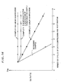
- Fig. 14 illustrates transition of imsge quality of the restored images as SN ratios of the image data f ij (k).
- SN ratios R SN corresponding to the case shown in Figs. 13A and 13B (Example 1) are shown with white circles.
- the SN ratio R SN is defined as follows: where f ij represents a difference between image data of an original and that of a restored image. Symbols X and Y in the expression (11b) represent numbers of colums and rows of pixels existing in the whole image (see Fig.1).
- the SN ratio R SN is not changed after the restored image data f ij (1) in the example 1, that is, the deterioration of image quality is prevented.
- Fig. 14 also shows a reference example, in which data compression and restoration are repeated without applying the present invention, for example.
- the compression groups is identified by the value of standard deviation ⁇
- the image data is decided to belong to the compression group g1 in the second data compression operation. Therefore, the image quality of a restored image after the second data compression is extremely deteriorated, and the value of its S N ratio R SN is also extremely reduced as shown in Fig. 14.
- Examples 2 and 3 will be described next, in which the quantization of F mn is performed.
- the transformation coefficients F mn are not subjected to the linear quantization.
- storage capacity required for preserving the transformation coefficients F mn can be extremely reduced and the compression rate can be further improved.
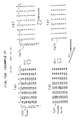
- Figs. 15A and 15B are explanatory diagrams showing image data f ij (k) and transformation coeffcients F mn *(k) with lineary quantization on the transformation coefficients F mn *.
- the subscripts * are attached to the transformation coefficients indicating that the same are linearly quantized.
- linear quantization Since the value of the quantum width ⁇ is "1", the term “linear quantization” herein used is the same as to round to the nearest whole number. The round-off operation is performed by counting fractions over 1/2 as one and disregarding the rest.
- the SN ratio R SN of the image data f ij (k) in the Example 2 shown in Figs. 15A and 15B is shown with black squares in Fig. 14.
- the SN ratio R SN of the Example 2 where the coefficients F mn are linearly quantized decreases more quickly than that of the Example 1 where the linear quantization is not executed
- the SN ratio R SN of the Example 2 decreases more slowly than that of the reference example, and the image quality is also lowered more slowly. It is because the errors caused by the round-off operation in the linear quantization of the transformation coefficients F mn are accumulated, dissimilarly to the case of the Example 1.
- Figs. 16A and 16B show examples of the image data f ij (k) and the transformation coefficients F mn * in the Example 3 where the modification of the transformation coefficients is performed.
- the SN ratio R SN of the Example 3 is shown with white squares in Fig. 14.
- the SN ratio R SN of the Example 3 holds relatevely large, and the SN ratio R SN is maintained constant after the second cycle of the data compression and restoration.
- the expressions (12a) and (12b) are introduced on the basis of the following idea:
- the image data f ij (1) of Fig. 15A which are restored with no modification of the transformation coefficients F mn *, are compared with the image data f ij (0), the restored image data f ij (1) have smaller differences of data values between the pixels. That is, the image data after one cycle of the data compression and restoration are averaged in the pixel block to some extent.
- of the transformation coefficients F mn * denote amplitudes of respective frequency components of the image data f ij restored as a function of the transformation coefficients F mn *, as shown in the expression (4).
- the SN ratio R SN is substantially equal to that of the Example 1 where the linear quantization is not performed and a large effect on suppressing progress of the deterioration of the image quality is attained. Further, since the transformation coefficients F mn * are linearly quantized and preserved, the compressed image data D t can be reduced to achieve high data compressibility.
- code tables are classified into a plurality of code table groups depending on the standard deviation of the image data in the above embodiment, such classification may be performed by means of variance or various statistical vlaue similar to the same, other than the standard deviation. That is, classification may be performed by means of some statistical value statistically representing distribution state of the image data.
- the present invention may be applied to respective color separation images as to a color image.
- respective color separation images of YMCK printed images, RGB signal images or Y S /I S /Q S signal (chroma signal) images are compressed respectively.
- data compression suitable for each color separation image can be achieved by varying the number of threshold values of standard deviation and values thereof, the number of code tables in each code tables group, the numbers of effective alternate current components of the code tables, and the patterns of effective bit numbers of the code tables for each color separation image.
- pixel positions (i, j) ((1, 1) and (3, 3) in the above embodiment) for recording the group information in the image data f ij to be varied with the respective color separation images. Since values of the least significant digits of the image data f ij in these pixel positions are adjusted in recording of the group information, such adjustment causes a small change of the image quality. Hence the change of the image quality is reduced as a whole if the pixel position whose least significant digit values are adjusted are not overlapped in overprinting respective color separation images. similarly, these pixel positions are preferably not adjacent to other pixel positions in the respective color separation images.
- the group information is expressed by means of the least significant digits of the image data f ij of the restored image in the above embodiment, the group information may be recorded as other data separately from the image data f ij .
- the image data are defined as that including not only the data f ij (hereinafter referred to as "image density data") representing density values of respective pixel positions but other data representing the group information.
- the method of the data compression and restoration is not restricted to that of the above embodiment, but various methods such as that disclosed in Japanese Open Laying Gazette No.109086/1980 can be applied.
- the present invention is applicable to a method of obtaining a statistical value substantially representing standard deviation of image data within pixel blocks and selecting one of prescribed procedures of data compression with response to the statistical value.
- four procedures of the data compression operation using one of the code table groups different for the compression groups g1 to g4 correspond to the "plurality of prescribed procedures".
- the purality of prescribed procedures are not distinguished by means of the compression groups dissimilarly to the above enbodiment, some identification data for identifying the selected procedure is included in the restored image data.
- compressed image data are also preserved with such identification data.
- the image data f11 and f33 in the restored image data f ij and the code table number Max in the compressed image data D t play the role of the identifying data, respectively.
- the present invention only a part of the transformation coefficients are employed to form the compressed image data, whereby the compression rate is increased without lowering the image quality.
- the image data are produced to include the identification data so that the same procedure as that employed in previous data compression can be applied to recompression of the restored image data, whereby progress of the deterioration of the image quality is suppressed even if the data compession and restoration are repeated many times.
- the identification data are expressed by means of the least significant digits of image data in prescribed pixel positions within a pixel block, there is no need to independently preserve the identification data. Consequently, the amount of restored image data is reduced while the deterioration of the image quality of the restored image is minimized.
Landscapes
- Engineering & Computer Science (AREA)
- Multimedia (AREA)
- Signal Processing (AREA)
- Compression Or Coding Systems Of Tv Signals (AREA)
- Compression Of Band Width Or Redundancy In Fax (AREA)
- Image Processing (AREA)
- Compression, Expansion, Code Conversion, And Decoders (AREA)
Applications Claiming Priority (4)
| Application Number | Priority Date | Filing Date | Title |
|---|---|---|---|
| JP165361/88 | 1988-06-30 | ||
| JP63165361A JPH0214672A (ja) | 1988-06-30 | 1988-06-30 | 画像データ圧縮方法 |
| JP321803/88 | 1988-12-19 | ||
| JP63321803A JPH0775398B2 (ja) | 1988-12-19 | 1988-12-19 | 画像処理システム |
Publications (3)
| Publication Number | Publication Date |
|---|---|
| EP0349847A2 true EP0349847A2 (de) | 1990-01-10 |
| EP0349847A3 EP0349847A3 (de) | 1991-10-09 |
| EP0349847B1 EP0349847B1 (de) | 1996-09-04 |
Family
ID=26490124
Family Applications (1)
| Application Number | Title | Priority Date | Filing Date |
|---|---|---|---|
| EP89111416A Expired - Lifetime EP0349847B1 (de) | 1988-06-30 | 1989-06-22 | Verfahren und Vorrichtung für die Bilddatenkomprimierung |
Country Status (3)
| Country | Link |
|---|---|
| US (1) | US5187755A (de) |
| EP (1) | EP0349847B1 (de) |
| DE (1) | DE68927082T2 (de) |
Cited By (9)
| Publication number | Priority date | Publication date | Assignee | Title |
|---|---|---|---|---|
| WO1991013516A3 (fr) * | 1990-02-26 | 1992-02-06 | Alcatel Bell Sdt Sa | Procede de codage de signaux d'image |
| EP0432806A3 (en) * | 1989-12-15 | 1992-05-20 | Dainippon Screen Mfg. Co., Ltd. | Method of and apparatus for compressing image data |
| US5335017A (en) * | 1993-01-08 | 1994-08-02 | Scott C. Harris | Method for encoding transmitting and receiving high definition television signals using single variable independent equations representing each pixel over time |
| EP0618734A3 (de) * | 1993-03-29 | 1995-01-04 | Sony Corp | Bildsignalverarbeitung. |
| US7606124B2 (en) | 2003-05-14 | 2009-10-20 | Sony Corporation | Image processing device and image processing method, information processing device and information processing method, information recording device and information recording method, information reproducing device and information reproducing method, storage medium, and program |
| US7680187B2 (en) | 1999-02-09 | 2010-03-16 | Sony Corporation | Coding system and method, encoding device and method, decoding device and method, recording device and method, and reproducing device and method |
| USRE43021E1 (en) | 1994-03-29 | 2011-12-13 | Sony Corporation | Picture signal transmitting method and apparatus |
| US8170118B2 (en) | 1999-12-03 | 2012-05-01 | Sony Corporation | Information processing apparatus, information processing method and recording medium |
| US8638849B2 (en) | 1998-03-10 | 2014-01-28 | Sony Corporation | Transcoding system using encoding history information |
Families Citing this family (29)
| Publication number | Priority date | Publication date | Assignee | Title |
|---|---|---|---|---|
| JP2844695B2 (ja) * | 1989-07-19 | 1999-01-06 | ソニー株式会社 | 信号符号化装置 |
| US5933538A (en) * | 1990-07-31 | 1999-08-03 | Fujitsu Limited | Image data processing method and apparatus |
| EP0469855B1 (de) | 1990-07-31 | 1999-12-01 | Fujitsu Limited | Verfahren und Gerät zur Bilddatenverarbeitung |
| US5875266A (en) * | 1990-07-31 | 1999-02-23 | Fujitsu Limited | Image data processing a method and apparatus |
| US5920349A (en) * | 1990-11-05 | 1999-07-06 | Canon Kabushiki Kaisha | Image pickup device |
| JP2945487B2 (ja) * | 1990-12-26 | 1999-09-06 | 株式会社日立製作所 | 行列乗算器 |
| JP2802694B2 (ja) * | 1991-10-30 | 1998-09-24 | 富士写真フイルム株式会社 | 画像再生装置および方法 |
| JP3105335B2 (ja) * | 1992-02-07 | 2000-10-30 | 株式会社ハドソン | 画像の直交変換符号化による圧縮・伸張方法 |
| JPH05298419A (ja) * | 1992-04-20 | 1993-11-12 | Ricoh Co Ltd | 画像ファイリング装置 |
| JPH05316360A (ja) * | 1992-05-14 | 1993-11-26 | Fuji Xerox Co Ltd | 画像信号の符号化復号装置 |
| JP3196906B2 (ja) * | 1992-08-21 | 2001-08-06 | 富士ゼロックス株式会社 | 画像信号の符号化装置 |
| US5379355A (en) * | 1992-08-24 | 1995-01-03 | Ricoh Corporation | Data encoding using one or more adaptive decision trees |
| JP2856300B2 (ja) * | 1993-02-19 | 1999-02-10 | 富士ゼロックス株式会社 | 画像符号化装置および復号装置 |
| EP0700547A1 (de) * | 1993-05-24 | 1996-03-13 | Motorola, Inc. | Verfahren und geraet zum speichern komprimierter daten einer nachfolgenden praesentation auf einer aktiven adressierten anzeigevorrichtung |
| MX9700385A (es) | 1994-07-14 | 1998-05-31 | Johnson Grace Company | Metodo y aparato para comprimir imagenes. |
| JPH08116448A (ja) * | 1994-10-13 | 1996-05-07 | Fuji Xerox Co Ltd | 画像信号の符号化装置及び復号装置 |
| US5727092A (en) * | 1995-05-17 | 1998-03-10 | The Regents Of The University Of California | Compression embedding |
| JP3792762B2 (ja) * | 1995-09-22 | 2006-07-05 | キヤノン株式会社 | 画像処理装置および画像処理方法 |
| US5710835A (en) * | 1995-11-14 | 1998-01-20 | The Regents Of The University Of California, Office Of Technology Transfer | Storage and retrieval of large digital images |
| US5949920A (en) * | 1996-08-13 | 1999-09-07 | Hewlett-Packard Co. | Reconfigurable convolver circuit |
| US6094453A (en) * | 1996-10-11 | 2000-07-25 | Digital Accelerator Corporation | Digital data compression with quad-tree coding of header file |
| SE521925C2 (sv) * | 1997-11-21 | 2003-12-16 | Ericsson Telefon Ab L M | Förfarande och anordning vid datakompromering |
| US6580837B1 (en) * | 1999-12-07 | 2003-06-17 | Intel Corporation | Up-sampling decimated color plane data |
| US8819723B1 (en) | 2000-04-27 | 2014-08-26 | The Directv Group, Inc. | System and method for brokering auxiliary data broadcasting services |
| JP3854790B2 (ja) * | 2000-08-22 | 2006-12-06 | キヤノン株式会社 | 画像処理装置及び方法及び記憶媒体 |
| US6961449B2 (en) * | 2001-01-16 | 2005-11-01 | University Of Massachusetts Lowell | Method of correlation of images in biometric applications |
| JP2005524260A (ja) * | 2002-04-23 | 2005-08-11 | キルバンク ダニエル | 通信においてマイクロレッツを使用するためのシステムおよび方法 |
| CN1296010C (zh) * | 2003-07-28 | 2007-01-24 | 东软飞利浦医疗设备系统有限责任公司 | 针对原始ct图像数据的压缩及解压缩方法 |
| US7424151B2 (en) * | 2004-06-04 | 2008-09-09 | Xerox Corporation | Method and system for image classification and halftone frequency detection |
Family Cites Families (7)
| Publication number | Priority date | Publication date | Assignee | Title |
|---|---|---|---|---|
| US4910609A (en) * | 1984-06-07 | 1990-03-20 | Raytel Systems Corporation | Teleradiology system |
| US4760461A (en) * | 1986-02-28 | 1988-07-26 | Kabushiki Kaisha Toshiba | Binary data compression and expansion processing apparatus |
| JPS62222783A (ja) * | 1986-03-24 | 1987-09-30 | Kokusai Denshin Denwa Co Ltd <Kdd> | 動画像の高能率符号化方式 |
| US4918541A (en) * | 1986-04-17 | 1990-04-17 | Canon Kabushiki Kaisha | Image processing method and apparatus |
| US4947447A (en) * | 1986-04-24 | 1990-08-07 | Hitachi, Ltd. | Method for data coding |
| EP0260721B1 (de) * | 1986-09-25 | 1993-12-01 | Nec Corporation | Verfahren und Apparat zur Kodierung von Bewegtbildsignalen |
| US4922273A (en) * | 1987-04-02 | 1990-05-01 | Konica Corporation | Compression method of halftone image data |
-
1989
- 1989-06-21 US US07/369,423 patent/US5187755A/en not_active Expired - Fee Related
- 1989-06-22 EP EP89111416A patent/EP0349847B1/de not_active Expired - Lifetime
- 1989-06-22 DE DE68927082T patent/DE68927082T2/de not_active Expired - Fee Related
Cited By (17)
| Publication number | Priority date | Publication date | Assignee | Title |
|---|---|---|---|---|
| EP0432806A3 (en) * | 1989-12-15 | 1992-05-20 | Dainippon Screen Mfg. Co., Ltd. | Method of and apparatus for compressing image data |
| US5204738A (en) * | 1989-12-15 | 1993-04-20 | Dainippon Screen Mfg. Co., Ltd. | Method of an apparatus for compressing images data |
| WO1991013516A3 (fr) * | 1990-02-26 | 1992-02-06 | Alcatel Bell Sdt Sa | Procede de codage de signaux d'image |
| US5335017A (en) * | 1993-01-08 | 1994-08-02 | Scott C. Harris | Method for encoding transmitting and receiving high definition television signals using single variable independent equations representing each pixel over time |
| EP0618734A3 (de) * | 1993-03-29 | 1995-01-04 | Sony Corp | Bildsignalverarbeitung. |
| US5473380A (en) * | 1993-03-29 | 1995-12-05 | Sony Corporation | Picture signal transmitting method and apparatus |
| USRE43238E1 (en) | 1994-03-29 | 2012-03-13 | Sony Corporation | Picture signal transmitting method and apparatus |
| USRE43021E1 (en) | 1994-03-29 | 2011-12-13 | Sony Corporation | Picture signal transmitting method and apparatus |
| USRE43043E1 (en) | 1994-03-29 | 2011-12-27 | Sony Corporation | Picture signal transmitting method and apparatus |
| USRE43111E1 (en) | 1994-03-29 | 2012-01-17 | Sony Corporation | Picture signal transmitting method and apparatus |
| US8638849B2 (en) | 1998-03-10 | 2014-01-28 | Sony Corporation | Transcoding system using encoding history information |
| US8687690B2 (en) | 1998-03-10 | 2014-04-01 | Sony Corporation | Transcoding system using encoding history information |
| US7680187B2 (en) | 1999-02-09 | 2010-03-16 | Sony Corporation | Coding system and method, encoding device and method, decoding device and method, recording device and method, and reproducing device and method |
| US8681868B2 (en) | 1999-02-09 | 2014-03-25 | Sony Corporation | Coding system and method, encoding device and method, decoding device and method, recording device and method, and reproducing device and method |
| US8170118B2 (en) | 1999-12-03 | 2012-05-01 | Sony Corporation | Information processing apparatus, information processing method and recording medium |
| US7859956B2 (en) | 2003-05-14 | 2010-12-28 | Sony Corporation | Image processing device and image processing method, information processing device and information processing method, information recording device and information recording method, information reproducing device and information reproducing method, storage medium, and program |
| US7606124B2 (en) | 2003-05-14 | 2009-10-20 | Sony Corporation | Image processing device and image processing method, information processing device and information processing method, information recording device and information recording method, information reproducing device and information reproducing method, storage medium, and program |
Also Published As
| Publication number | Publication date |
|---|---|
| EP0349847B1 (de) | 1996-09-04 |
| DE68927082D1 (de) | 1996-10-10 |
| US5187755A (en) | 1993-02-16 |
| EP0349847A3 (de) | 1991-10-09 |
| DE68927082T2 (de) | 1997-04-10 |
Similar Documents
| Publication | Publication Date | Title |
|---|---|---|
| EP0349847A2 (de) | Verfahren und Vorrichtung für die Bilddatenkomprimierung | |
| KR950004117B1 (ko) | 직교변환 부호화장치 | |
| EP0107426B1 (de) | Bildübertragung | |
| US6449395B1 (en) | Image encoding apparatus, image encoding method, and recording medium in which image encoding program is recorded | |
| EP0558016A2 (de) | Verfahren und Vorrichtung zur Bildsignalkodierung mit merhstufigen Quantisierungnummernbestimmung | |
| MXPA02010002A (es) | Compresion mejorada de imagenes de nivel gris. | |
| US5719961A (en) | Adaptive technique for encoder and decoder signal transformation | |
| JPH0563996A (ja) | 画像処理装置 | |
| JPH07184057A (ja) | 最小圧縮比のadct圧縮方法 | |
| US5461682A (en) | Image filing apparatus providing image data suitable for several input/output devices | |
| JPH04328960A (ja) | 画像データ伝送装置および画像データ伝送方法 | |
| KR960001483B1 (ko) | 직교변환 부호화장치 | |
| JP2004528791A (ja) | インターフレーム符号化方法および装置 | |
| JP3532963B2 (ja) | 画像圧縮装置 | |
| JP3359215B2 (ja) | 多値画像符号化装置 | |
| JP3108133B2 (ja) | カラー文書画像の適応符号化方式 | |
| GB2308771A (en) | Video encoding based on inter block correlation | |
| US5825422A (en) | Method and apparatus for encoding a video signal based on inter-block redundancies | |
| WO2002013539A1 (en) | Sub-optimal variable length coding | |
| JPH0856358A (ja) | 画像データ符号化装置 | |
| JP3306201B2 (ja) | データ圧縮装置 | |
| JP3017510B2 (ja) | 圧縮データ量制御方法 | |
| JPH089373A (ja) | 画像圧縮装置 | |
| Alhadi | Compression of Medical Images Based on 2D-Discrete Cosine Transform and Vector Quantization Algorithms | |
| JP2950559B2 (ja) | 画像処理方法および装置 |
Legal Events
| Date | Code | Title | Description |
|---|---|---|---|
| PUAI | Public reference made under article 153(3) epc to a published international application that has entered the european phase |
Free format text: ORIGINAL CODE: 0009012 |
|
| AK | Designated contracting states |
Kind code of ref document: A2 Designated state(s): DE FR GB IT |
|
| PUAL | Search report despatched |
Free format text: ORIGINAL CODE: 0009013 |
|
| AK | Designated contracting states |
Kind code of ref document: A3 Designated state(s): DE FR GB IT |
|
| 17P | Request for examination filed |
Effective date: 19920109 |
|
| 17Q | First examination report despatched |
Effective date: 19931102 |
|
| GRAH | Despatch of communication of intention to grant a patent |
Free format text: ORIGINAL CODE: EPIDOS IGRA |
|
| GRAH | Despatch of communication of intention to grant a patent |
Free format text: ORIGINAL CODE: EPIDOS IGRA |
|
| GRAA | (expected) grant |
Free format text: ORIGINAL CODE: 0009210 |
|
| AK | Designated contracting states |
Kind code of ref document: B1 Designated state(s): DE FR GB IT |
|
| PG25 | Lapsed in a contracting state [announced via postgrant information from national office to epo] |
Ref country code: FR Effective date: 19960904 Ref country code: IT Free format text: LAPSE BECAUSE OF FAILURE TO SUBMIT A TRANSLATION OF THE DESCRIPTION OR TO PAY THE FEE WITHIN THE PRE;WARNING: LAPSES OF ITALIAN PATENTS WITH EFFECTIVE DATE BEFORE 2007 MAY HAVE OCCURRED AT ANY TIME BEFORE 2007. THE CORRECT EFFECTIVE DATE MAY BE DIFFERENT FROM THE ONE RECORDED.SCRIBED TIME-LIMIT Effective date: 19960904 |
|
| REF | Corresponds to: |
Ref document number: 68927082 Country of ref document: DE Date of ref document: 19961010 |
|
| EN | Fr: translation not filed | ||
| PLBE | No opposition filed within time limit |
Free format text: ORIGINAL CODE: 0009261 |
|
| STAA | Information on the status of an ep patent application or granted ep patent |
Free format text: STATUS: NO OPPOSITION FILED WITHIN TIME LIMIT |
|
| 26N | No opposition filed | ||
| PGFP | Annual fee paid to national office [announced via postgrant information from national office to epo] |
Ref country code: GB Payment date: 19980617 Year of fee payment: 10 |
|
| PGFP | Annual fee paid to national office [announced via postgrant information from national office to epo] |
Ref country code: DE Payment date: 19980629 Year of fee payment: 10 |
|
| PG25 | Lapsed in a contracting state [announced via postgrant information from national office to epo] |
Ref country code: GB Free format text: LAPSE BECAUSE OF NON-PAYMENT OF DUE FEES Effective date: 19990622 |
|
| GBPC | Gb: european patent ceased through non-payment of renewal fee |
Effective date: 19990622 |
|
| PG25 | Lapsed in a contracting state [announced via postgrant information from national office to epo] |
Ref country code: DE Free format text: LAPSE BECAUSE OF NON-PAYMENT OF DUE FEES Effective date: 20000503 |