EP0349813B1 - Blendeneinstellvorrichtung in einem fotografischen Vergrösserungs- oder Kopiergerät mit mehreren Objektiven mit verstellbarer Blende - Google Patents
Blendeneinstellvorrichtung in einem fotografischen Vergrösserungs- oder Kopiergerät mit mehreren Objektiven mit verstellbarer Blende Download PDFInfo
- Publication number
- EP0349813B1 EP0349813B1 EP89111065A EP89111065A EP0349813B1 EP 0349813 B1 EP0349813 B1 EP 0349813B1 EP 89111065 A EP89111065 A EP 89111065A EP 89111065 A EP89111065 A EP 89111065A EP 0349813 B1 EP0349813 B1 EP 0349813B1
- Authority
- EP
- European Patent Office
- Prior art keywords
- aperture
- copying apparatus
- lenses
- drive
- apertures
- Prior art date
- Legal status (The legal status is an assumption and is not a legal conclusion. Google has not performed a legal analysis and makes no representation as to the accuracy of the status listed.)
- Expired - Lifetime
Links
Images


Classifications
-
- G—PHYSICS
- G03—PHOTOGRAPHY; CINEMATOGRAPHY; ANALOGOUS TECHNIQUES USING WAVES OTHER THAN OPTICAL WAVES; ELECTROGRAPHY; HOLOGRAPHY
- G03B—APPARATUS OR ARRANGEMENTS FOR TAKING PHOTOGRAPHS OR FOR PROJECTING OR VIEWING THEM; APPARATUS OR ARRANGEMENTS EMPLOYING ANALOGOUS TECHNIQUES USING WAVES OTHER THAN OPTICAL WAVES; ACCESSORIES THEREFOR
- G03B27/00—Photographic printing apparatus
- G03B27/32—Projection printing apparatus, e.g. enlarger, copying camera
- G03B27/34—Means for automatic focusing therefor
- G03B27/36—Means for automatic focusing therefor by mechanical connections, e.g. by cam, by linkage
- G03B27/40—Means for automatic focusing therefor by mechanical connections, e.g. by cam, by linkage adapted for use with lenses of different focal length
Definitions
- the invention relates to a photographic enlarger or copier with a plurality of lenses with an adjustable aperture and an aperture setting device according to the preamble of claim 1.
- Known photographic enlargers are set up in such a way that they can be used to produce photographic prints in different formats and on the basis of copying templates, which are also available in different formats.
- magnification devices are equipped with several lenses of different focal lengths, which can be moved into the working position.
- Each lens is usually also equipped with an adjustable aperture to adjust the intensity of the copying light to the specific conditions of the exposure to be carried out.
- German patent DE-C 30 45 157 describes a lens slide with three lenses, where the diaphragms of the individual lenses can be manually adjusted to predetermined positions, each corresponding to a fixed aperture value, using a common adjuster and the setting positions by means of correspondingly arranged, one below the other and with a series of signal lamps electrically connected microswitches are detected.
- Such a device is suitable for setting and capturing only a limited number of aperture values and is also unsuitable for inclusion in an automatic control system, as is the case with modern magnification devices in connection with the exposure control and other measuring and control functions.
- the manual adjustment of the lens hoods means not only a restriction of the automatic operation of the enlarger with a corresponding extension of the processing times; it is also a source of error because of the risk that the aperture value on which the exposure calculation is based does not match the aperture value that is actually set. Without direct communication between the aperture setting and the exposure control of the enlarger, it is left to the operator to set the aperture value on which the exposure calculation is based or to correctly transfer a set aperture value to the exposure control.
- a control circuit for the automatic setting of a motor-driven lens aperture of a film camera is also known.
- light reflected from a sector lamella is measured and evaluated and the diaphragm is set to a value corresponding to the film exposure required in each case by means of a direct current motor which is controlled by the size and direction of the diagonal voltage of a resistance bridge circuit.
- a photographic copying device is known from EP-A-0 250 368, the lighting device of which has a variable lighting objective (zoom) with movable lenses, by means of which the size of the original surfaces acted upon by the copying light can be adapted to the respectively set original format.
- the lenses are adjusted by means of stepper motors which are connected to an electronic control circuit which receives information about the format of the copy template.
- the object of the invention is to provide an aperture setting device in a magnifying device with a plurality of lenses with an adjustable aperture, in which the aperture setting can be continuously controlled and the aperture of each lens can be automatically adjusted to predetermined values in adaptation to the individual setting characteristics.
- the device should be simple and space-saving in construction, so that it is suitable for an optics carrier of compact design.
- an aperture setting device which has means for jointly adjusting the apertures of all lenses and means for detecting the actual position of the apertures and is characterized in that the means for detecting the actual position of the Orifices are designed for continuous position detection, the means for adjusting the orifices comprise a motor drive, and that the orifice adjusting device comprises a control circuit which, by comparing the actual position of the orifices with a predetermined desired position, provides a control signal for the drive for moving the Apertures generated in the intended target position, and that a device for identifying the lens in the working position is further provided for a differentiated control of the aperture of each lens according to its individual setting characteristics.
- the diaphragms of the individual lenses are motionally connected via a toothed belt which encompasses the diaphragm rings and the drive.
- a particularly advantageous and space-saving design results through the use of a stepper motor, because the number of steps performed directly gives a measure of the adjustment path, without the need for other devices for position detection.
- a DC motor can be used as the drive in conjunction with a separate displacement sensor for the adjustment path.
- the aperture setting is controlled by a microprocessor system. This offers the possibility of taking the individual control characteristics of the aperture of each individual lens into account in the execution of the control program.
- the reference number 1 denotes a photographic enlarger, which essentially comprises a base board 2, a support column 3 and an illumination and projection head 4 carried by the latter.
- the latter is fastened to a holding block 5, which is guided by rollers 6, which bear against the support column on opposite sides thereof, and along the support column is adjustable.
- a gear 7 driven by a motor 8 is in engagement with a toothed section 9 of the support column. In this way, the projection head 4 can be moved along the support column by a motor and can thus be moved to a desired height position above the base board.
- the projection head 4 comprises a light source 10, the light of which illuminates a copy template 11 held in an image stage 12, which is imaged by an objective 13 of an optics carrier 14 onto the photo paper 15 arranged on the base board.
- the optics carrier 14 is held on the projection head 4 and can be displaced along guide rods 16 in the direction of the projection axis relative to the original plane.
- a toothed rack 17 fixedly attached to the optics carrier engages with a toothed wheel 18 which is fastened to the body of the projection head and is driven by a motor 19.
- the optics carrier itself comprises a rotating plate 20 driven by a motor 21, which carries a plurality of lenses 13, 13 'and is rotatable about a central axis so that the individual lenses alternately get into the working position on the projection axis.
- the image stage optics carrier area is surrounded by a light-tight bellows 22.
- the magnification scale can be adjusted within a wide range by changing the distance between the original image and the copying plane in connection with the choice of a lens having a suitable focal length, in order to take into account the different formats of both the original copies and the desired prints.
- the projected image is focused for each selected magnification by adjusting the optics carrier relative to the original image.
- the optics carrier 14 is described in more detail below, in particular with regard to the aperture setting of the lenses used. Identical parts are identified in the figures with the same reference number.
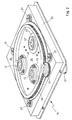
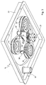
- the optics carrier consists of an essentially rectangular one Frame 23 with a bottom 24 which has an extensive round opening 25.
- a circular lens support plate 26 is held on the circumference by four guide rollers 27 which are rotatably mounted at a distance from one another on the base 24, such that the plate 26 can be rotated in a plane parallel to the base in a manner superimposed on the central opening of the base.
- the plate 26 has on its side facing the frame an annular projection 28 which engages freely in a corresponding groove 29 in the base 24. This creates a light trap that prevents light from passing from one side of the optics carrier to the other.
- the lens support plate has a concentric ring gear 30 which is coupled via a gear wheel 31 to an electric motor 32 fastened to the frame.
- the lens support plate 26 is designed for receiving three lenses 13, 13 ', 13 ⁇ , which are arranged on a circle concentric with the axis of rotation, which intersects the axis of the projection system. In this way, one lens after the other enters the area of the projection axis when the plate is rotated.
- the lenses 13, 13 'and 13 ⁇ are screwed into their own adapter rings 33, 33' and 33 ⁇ , which in turn are fastened with a screw connection on the lens support plate.
- the attachment is designed so that the rotational position of at least two adapter rings is adjustable, whereby the mutual rotational position of the lenses screwed into the adapter rings can be changed.
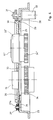
- Each adapter ring is adapted to the screwed-in lens in such a way that when the lenses are screwed in, the aperture rings 34, 34 'and 34 ⁇ , with which the individual lenses are equipped, come to lie in the same plane in the area below the lens support plate 26, such as clearly visible in FIGS. 3 and 4.
- the aperture rings have a toothing on the outer circumference and are connected to one another in motion by a toothed belt 35 which runs over a drive toothed wheel 36.
- the gear wheel 36 is coupled to an electric motor 37 which is fastened on the lens carrier plate and moves with it.
- the timing belt is in the sections between the individual aperture rings over guide rollers 38, which are rotatably mounted on fixed, protruding bolts from the lens support plate and are arranged so that the support of the toothed belt on the aperture rings and on the drive gear 36 is guaranteed.
- One of the guide rollers 38 is also biased with a return spring 39 radially towards the center of the lens support plate, so that it performs the function of a belt tensioner.
- the frame 23 together with the lens carrier plate is part of the optics carrier 14 and moves with it in the direction of the projection axis of the exposure system as indicated above with reference to FIG. 1.
- the mode of operation is described below with reference to the functional circuit diagram in FIG are as in the previous figures.
- the number 26 denotes the lens support plate, with the numbers 13, 13 'and 13 ⁇ three lenses mounted on the support plate, with 34, 34' and 34 ⁇ the aperture rings of the individual lenses and with 37 their servomotor.
- the line labeled 39 schematically shows a dynamic coupling between the aperture rings and the drive motor.
- the center of the diaphragm control is a microprocessor system 41, comprising a central processor unit 42 and peripheral elements such as a read memory (ROM) 43 as program memory, a read-write memory (RAM) 44 as data memory and a timer (clock) 45.
- the microprocessor system is more than one Input interface 46 a data and command input unit 47 and or signal output of a position detector 50 connected, which indicates the rotational position of the lens support plate 26 with respect to the identification of the lens in the working position.
- a motor control unit 49 for the diaphragm actuator 37 and the drive motor 32 of the lens support plate are via an output interface 48 connected to the microprocessor system.
- the servomotor 37 is a stepper motor and the number of control pulses fed to it determines the extent of the rotary movement of the motor shaft and is thus indirectly a measure of the diaphragm adjustment path. Due to the fixed assignment of the diaphragm values to the rotational position of the diaphragm rings, the counting of the control impulses or the motor steps continuously delivers the current diaphragm value starting from a starting or reference position. The end stop of the diaphragm rings in the direction of the lowest diaphragm value is advantageously selected as the starting position.
- the microprocessor system is programmed in such a way that it compares the recorded actual aperture value with a predetermined, previously entered value, determines from the comparison the number of motor steps that are required to adjust the aperture to the specified value and controls the servomotor accordingly.
- the system is therefore suitable for the automatic setting of the diaphragms to a desired value previously entered via the data input unit 47.
- the microprocessor system receives information about which of the lenses is in the working position via the position detector 50 of the lens support plate 26 and the processor program can take into account the individual setting characteristics of each aperture.
- a differentiated one Adjustment of the individual diaphragms can also be achieved by a suitable choice of the transmission ratio between the drive and the respective diaphragm ring, for example by using diaphragm rings of different diameters.
- a DC motor can also be used as the servomotor, to which a separate device for detecting the aperture value is assigned on the basis of the position of the aperture rings.
- a separate device for detecting the aperture value is assigned on the basis of the position of the aperture rings.
- Such a device is shown in broken lines in FIG. 5, the reference number 51 designating a displacement sensor which indicates the adjustment path of the diaphragm rings in relation to an initial position and thus provides a signal representative of the set diaphragm value.
- a potentiometer, the wiper of which is coupled to the aperture rings can be used, for example, as a displacement sensor in such a device. If a fixed voltage is present at the potentiometer resistor, a voltage is set at the potentiometer tap, which is an analog measurement signal for the aperture value and as such is supplied to the microprocessor system in digitized form.
- the aperture setting may be desirable to limit the aperture setting to a series of discrete aperture values, for example 5.6 - 8 - 11 - 16.
- the microprocessor system is prepared so that only the input of these values is accepted.
- the microprocessor system advantageously also performs control functions in connection with the determination of the exposure values and the control of the exposure process, as is known from modern photographic copying machines and is therefore not described in more detail here.
Landscapes
- Physics & Mathematics (AREA)
- General Physics & Mathematics (AREA)
- Projection-Type Copiers In General (AREA)
- Optical Systems Of Projection Type Copiers (AREA)
- Control Of Exposure In Printing And Copying (AREA)
- Variable Magnification In Projection-Type Copying Machines (AREA)
- Mounting And Adjusting Of Optical Elements (AREA)
- Exposure Control For Cameras (AREA)
- Diaphragms And Bellows (AREA)
- Diaphragms For Cameras (AREA)
Priority Applications (1)
| Application Number | Priority Date | Filing Date | Title |
|---|---|---|---|
| AT89111065T ATE102714T1 (de) | 1988-07-03 | 1989-06-19 | Blendeneinstellvorrichtung in einem fotografischen vergroesserungs- oder kopiergeraet mit mehreren objektiven mit verstellbarer blende. |
Applications Claiming Priority (2)
| Application Number | Priority Date | Filing Date | Title |
|---|---|---|---|
| IT8804839A IT1224919B (it) | 1988-07-03 | 1988-07-03 | Dispositivo regolatore di diaframma in un ingranditore o riproduttore fotografico con piu' obiettivi a diaframma regolabile. |
| IT483988 | 1988-07-03 |
Publications (3)
| Publication Number | Publication Date |
|---|---|
| EP0349813A2 EP0349813A2 (de) | 1990-01-10 |
| EP0349813A3 EP0349813A3 (en) | 1991-07-03 |
| EP0349813B1 true EP0349813B1 (de) | 1994-03-09 |
Family
ID=11114768
Family Applications (1)
| Application Number | Title | Priority Date | Filing Date |
|---|---|---|---|
| EP89111065A Expired - Lifetime EP0349813B1 (de) | 1988-07-03 | 1989-06-19 | Blendeneinstellvorrichtung in einem fotografischen Vergrösserungs- oder Kopiergerät mit mehreren Objektiven mit verstellbarer Blende |
Country Status (6)
| Country | Link |
|---|---|
| US (1) | US4961087A (it) |
| EP (1) | EP0349813B1 (it) |
| JP (1) | JPH0328840A (it) |
| AT (1) | ATE102714T1 (it) |
| DE (1) | DE58907156D1 (it) |
| IT (1) | IT1224919B (it) |
Families Citing this family (7)
| Publication number | Priority date | Publication date | Assignee | Title |
|---|---|---|---|---|
| US5097289A (en) * | 1990-02-21 | 1992-03-17 | Orren J. Lucht | Photographic printer |
| KR960015077B1 (ko) * | 1993-03-30 | 1996-10-24 | 엘지전자 주식회사 | 액정투사기의 화면크기 제어방법 |
| US5576792A (en) * | 1995-05-19 | 1996-11-19 | Eastman Kodak Company | Method for assembling an iris diaphragm |
| US5635999A (en) * | 1995-05-19 | 1997-06-03 | Eastman Kodak Company | Iris diaphragm for high speed photographic printers having improved speed and reliability |
| US5552939A (en) * | 1995-07-07 | 1996-09-03 | Umax Data Systems Inc. | Multi-lens changing mechanism for use in optical scanners |
| US5758955A (en) * | 1995-07-11 | 1998-06-02 | High End Systems, Inc. | Lighting system with variable shaped beam |
| US5767950A (en) * | 1996-04-15 | 1998-06-16 | Eastman Kodak Company | Method and apparatus for calibrating iris of photographic printer |
Family Cites Families (6)
| Publication number | Priority date | Publication date | Assignee | Title |
|---|---|---|---|---|
| US2871776A (en) * | 1953-07-30 | 1959-02-03 | Gen Precision Lab Inc | Television camera iris control mechanism |
| DE1597237A1 (de) * | 1967-06-05 | 1970-04-09 | Inst Polygraphische Maschinen | Anordnung zur Verstellung wahlweise verstellbarer Blenden in Objektiven an Zweiraum-Reproduktionskameras |
| JPS5111973Y2 (it) * | 1971-04-19 | 1976-03-31 | ||
| DE2966442D1 (en) * | 1979-05-28 | 1984-01-05 | Oce Helioprint As | Lens turret |
| DE3045157C2 (de) * | 1980-12-01 | 1983-02-10 | Dr. Böger Duplomat Apparate KG (GmbH & Co), 2000 Wedel | Objektivschlittenanordnung an einer Reproduktionskamera |
| DE3763914D1 (de) * | 1986-06-20 | 1990-08-30 | Gretag Ag | Fotografische kopiervorrichtung. |
-
1988
- 1988-07-03 IT IT8804839A patent/IT1224919B/it active
-
1989
- 1989-06-19 EP EP89111065A patent/EP0349813B1/de not_active Expired - Lifetime
- 1989-06-19 AT AT89111065T patent/ATE102714T1/de not_active IP Right Cessation
- 1989-06-19 DE DE89111065T patent/DE58907156D1/de not_active Expired - Fee Related
- 1989-06-29 US US07/374,236 patent/US4961087A/en not_active Expired - Fee Related
- 1989-06-30 JP JP1167192A patent/JPH0328840A/ja active Pending
Also Published As
| Publication number | Publication date |
|---|---|
| EP0349813A3 (en) | 1991-07-03 |
| ATE102714T1 (de) | 1994-03-15 |
| JPH0328840A (ja) | 1991-02-07 |
| DE58907156D1 (de) | 1994-04-14 |
| EP0349813A2 (de) | 1990-01-10 |
| IT1224919B (it) | 1990-10-29 |
| US4961087A (en) | 1990-10-02 |
| IT8804839A0 (it) | 1988-07-03 |
Similar Documents
| Publication | Publication Date | Title |
|---|---|---|
| EP1186956B1 (de) | Projektionsbelichtungsanlage | |
| DE3430750C2 (it) | ||
| DE3034049C2 (de) | Vorrichtung zum Einstellen der Abbildungsgröße bei Kopiergeräten | |
| DE2805030A1 (de) | Verfahren und vorrichtung zum automatischen fokussieren einer reproduktionskamera | |
| EP0349813B1 (de) | Blendeneinstellvorrichtung in einem fotografischen Vergrösserungs- oder Kopiergerät mit mehreren Objektiven mit verstellbarer Blende | |
| DE3218335A1 (de) | Zoomobjektivanordnung mit einer autofokussiereinrichtung | |
| DE3228962C2 (it) | ||
| DE3400293C2 (it) | ||
| DE2410744C3 (de) | Zoomobjektiv | |
| DE3939306B4 (de) | Kameraverschluß mit Objektivverstellmechanismus | |
| DE2528789C2 (de) | Reproduktionsapparat | |
| DE3203851A1 (de) | Aufzeichnungsgeraet zum erzeugen von bildern auf einem lichtempfindlichen material unter verwendung einer codierten optischen einrichtung | |
| DE3916003C2 (it) | ||
| EP0250368B1 (de) | Fotografische Kopiervorrichtung | |
| DE3903263C2 (de) | Verfahren zur Scharfeinstellung eines Objektives in einem fotografischen Vergrößerungsgerät | |
| EP0261407B1 (de) | Verfahren und Vorrichtung zum automatischen Scharfstellen in einem fotografischen Vergrösserungs- oder Kopiergerät mit veränderlichem Vergrösserungsmassstab | |
| DE3016068C2 (de) | Schlitzbelichtungseinrichtung | |
| DE3339991A1 (de) | Fotografisches rollenkopiergeraet | |
| DE3234933C2 (it) | ||
| DE3013951C2 (de) | Lichtsetzmaschine mit grundliniensteuernder Schriftscheibe | |
| DE2925329C2 (de) | Belichtungseinrichtung für ein Kopiergerät, insbesondere für die lichtempfindliche Trommel eines elektrophotographischen Kopiergerätes | |
| DE4011048C2 (de) | Belichtungsmeßeinheit mit variablem Öffnungswinkel | |
| DE3046661C2 (de) | Einrichtung zum Schwenken eines Objektivs in den Strahlengang eines optischen Gerätes und zur nachfolgenden Blendeneinstellung | |
| DE10210258A1 (de) | Scanner mit Mehrfachauflösung | |
| DE2219849C3 (de) | Verfahren und Einrichtung zum Einstellen des Kontrasts bei photografischen Aufnahmen |
Legal Events
| Date | Code | Title | Description |
|---|---|---|---|
| PUAI | Public reference made under article 153(3) epc to a published international application that has entered the european phase |
Free format text: ORIGINAL CODE: 0009012 |
|
| AK | Designated contracting states |
Kind code of ref document: A2 Designated state(s): AT BE CH DE ES FR GB GR LI NL SE |
|
| PUAL | Search report despatched |
Free format text: ORIGINAL CODE: 0009013 |
|
| AK | Designated contracting states |
Kind code of ref document: A3 Designated state(s): AT BE CH DE ES FR GB GR LI NL SE |
|
| 17P | Request for examination filed |
Effective date: 19910723 |
|
| 17Q | First examination report despatched |
Effective date: 19930312 |
|
| RAP1 | Party data changed (applicant data changed or rights of an application transferred) |
Owner name: DURST PHOTOTECHNIK A.G. |
|
| RAP3 | Party data changed (applicant data changed or rights of an application transferred) |
Owner name: DURST PHOTOTECHNIK A.G. |
|
| GRAA | (expected) grant |
Free format text: ORIGINAL CODE: 0009210 |
|
| AK | Designated contracting states |
Kind code of ref document: B1 Designated state(s): AT BE CH DE ES FR GB GR LI NL SE |
|
| PG25 | Lapsed in a contracting state [announced via postgrant information from national office to epo] |
Ref country code: SE Free format text: THE PATENT HAS BEEN ANNULLED BY A DECISION OF A NATIONAL AUTHORITY Effective date: 19940309 Ref country code: GR Free format text: LAPSE BECAUSE OF FAILURE TO SUBMIT A TRANSLATION OF THE DESCRIPTION OR TO PAY THE FEE WITHIN THE PRESCRIBED TIME-LIMIT Effective date: 19940309 Ref country code: ES Free format text: THE PATENT HAS BEEN ANNULLED BY A DECISION OF A NATIONAL AUTHORITY Effective date: 19940309 Ref country code: BE Effective date: 19940309 |
|
| REF | Corresponds to: |
Ref document number: 102714 Country of ref document: AT Date of ref document: 19940315 Kind code of ref document: T |
|
| REF | Corresponds to: |
Ref document number: 58907156 Country of ref document: DE Date of ref document: 19940414 |
|
| PG25 | Lapsed in a contracting state [announced via postgrant information from national office to epo] |
Ref country code: AT Effective date: 19940619 |
|
| ET | Fr: translation filed | ||
| GBT | Gb: translation of ep patent filed (gb section 77(6)(a)/1977) |
Effective date: 19940615 |
|
| PLBE | No opposition filed within time limit |
Free format text: ORIGINAL CODE: 0009261 |
|
| STAA | Information on the status of an ep patent application or granted ep patent |
Free format text: STATUS: NO OPPOSITION FILED WITHIN TIME LIMIT |
|
| 26N | No opposition filed | ||
| PGFP | Annual fee paid to national office [announced via postgrant information from national office to epo] |
Ref country code: CH Payment date: 19960523 Year of fee payment: 8 |
|
| PGFP | Annual fee paid to national office [announced via postgrant information from national office to epo] |
Ref country code: GB Payment date: 19960610 Year of fee payment: 8 |
|
| PGFP | Annual fee paid to national office [announced via postgrant information from national office to epo] |
Ref country code: NL Payment date: 19960627 Year of fee payment: 8 |
|
| PGFP | Annual fee paid to national office [announced via postgrant information from national office to epo] |
Ref country code: FR Payment date: 19960628 Year of fee payment: 8 |
|
| PG25 | Lapsed in a contracting state [announced via postgrant information from national office to epo] |
Ref country code: GB Free format text: LAPSE BECAUSE OF NON-PAYMENT OF DUE FEES Effective date: 19970619 |
|
| PG25 | Lapsed in a contracting state [announced via postgrant information from national office to epo] |
Ref country code: LI Free format text: LAPSE BECAUSE OF NON-PAYMENT OF DUE FEES Effective date: 19970630 Ref country code: CH Free format text: LAPSE BECAUSE OF NON-PAYMENT OF DUE FEES Effective date: 19970630 |
|
| PG25 | Lapsed in a contracting state [announced via postgrant information from national office to epo] |
Ref country code: NL Effective date: 19980101 |
|
| GBPC | Gb: european patent ceased through non-payment of renewal fee |
Effective date: 19970619 |
|
| REG | Reference to a national code |
Ref country code: CH Ref legal event code: PL |
|
| PG25 | Lapsed in a contracting state [announced via postgrant information from national office to epo] |
Ref country code: FR Free format text: LAPSE BECAUSE OF NON-PAYMENT OF DUE FEES Effective date: 19980227 |
|
| NLV4 | Nl: lapsed or anulled due to non-payment of the annual fee |
Effective date: 19980101 |
|
| REG | Reference to a national code |
Ref country code: FR Ref legal event code: ST |
|
| REG | Reference to a national code |
Ref country code: FR Ref legal event code: ST |
|
| PGFP | Annual fee paid to national office [announced via postgrant information from national office to epo] |
Ref country code: DE Payment date: 20000628 Year of fee payment: 12 |
|
| PG25 | Lapsed in a contracting state [announced via postgrant information from national office to epo] |
Ref country code: DE Free format text: LAPSE BECAUSE OF NON-PAYMENT OF DUE FEES Effective date: 20020403 |