EP0349737A2 - Procédé pour commander un appareil de chauffage et appareil de chauffage - Google Patents
Procédé pour commander un appareil de chauffage et appareil de chauffage Download PDFInfo
- Publication number
- EP0349737A2 EP0349737A2 EP89108665A EP89108665A EP0349737A2 EP 0349737 A2 EP0349737 A2 EP 0349737A2 EP 89108665 A EP89108665 A EP 89108665A EP 89108665 A EP89108665 A EP 89108665A EP 0349737 A2 EP0349737 A2 EP 0349737A2
- Authority
- EP
- European Patent Office
- Prior art keywords
- heater
- load
- control device
- load level
- heating device
- Prior art date
- Legal status (The legal status is an assumption and is not a legal conclusion. Google has not performed a legal analysis and makes no representation as to the accuracy of the status listed.)
- Withdrawn
Links
- 238000000034 method Methods 0.000 title claims abstract description 23
- 238000010438 heat treatment Methods 0.000 title abstract description 25
- 230000015572 biosynthetic process Effects 0.000 claims description 2
- 238000012544 monitoring process Methods 0.000 claims 2
- 230000006641 stabilisation Effects 0.000 claims 1
- 238000011105 stabilization Methods 0.000 claims 1
- 238000002485 combustion reaction Methods 0.000 description 4
- 239000007788 liquid Substances 0.000 description 4
- XLYOFNOQVPJJNP-UHFFFAOYSA-N water Substances O XLYOFNOQVPJJNP-UHFFFAOYSA-N 0.000 description 4
- 230000001419 dependent effect Effects 0.000 description 3
- 238000010586 diagram Methods 0.000 description 2
- 238000010304 firing Methods 0.000 description 2
- 238000010521 absorption reaction Methods 0.000 description 1
- 238000001514 detection method Methods 0.000 description 1
- 230000007257 malfunction Effects 0.000 description 1
- 238000011017 operating method Methods 0.000 description 1
Images

Classifications
-
- F—MECHANICAL ENGINEERING; LIGHTING; HEATING; WEAPONS; BLASTING
- F24—HEATING; RANGES; VENTILATING
- F24H—FLUID HEATERS, e.g. WATER OR AIR HEATERS, HAVING HEAT-GENERATING MEANS, e.g. HEAT PUMPS, IN GENERAL
- F24H9/00—Details
- F24H9/20—Arrangement or mounting of control or safety devices
-
- B—PERFORMING OPERATIONS; TRANSPORTING
- B60—VEHICLES IN GENERAL
- B60H—ARRANGEMENTS OF HEATING, COOLING, VENTILATING OR OTHER AIR-TREATING DEVICES SPECIALLY ADAPTED FOR PASSENGER OR GOODS SPACES OF VEHICLES
- B60H1/00—Heating, cooling or ventilating [HVAC] devices
- B60H1/22—Heating, cooling or ventilating [HVAC] devices the heat being derived otherwise than from the propulsion plant
- B60H1/2203—Heating, cooling or ventilating [HVAC] devices the heat being derived otherwise than from the propulsion plant the heat being derived from burners
- B60H1/2206—Heating, cooling or ventilating [HVAC] devices the heat being derived otherwise than from the propulsion plant the heat being derived from burners controlling the operation of burners
-
- F—MECHANICAL ENGINEERING; LIGHTING; HEATING; WEAPONS; BLASTING
- F23—COMBUSTION APPARATUS; COMBUSTION PROCESSES
- F23N—REGULATING OR CONTROLLING COMBUSTION
- F23N1/00—Regulating fuel supply
- F23N1/002—Regulating fuel supply using electronic means
-
- B—PERFORMING OPERATIONS; TRANSPORTING
- B60—VEHICLES IN GENERAL
- B60H—ARRANGEMENTS OF HEATING, COOLING, VENTILATING OR OTHER AIR-TREATING DEVICES SPECIALLY ADAPTED FOR PASSENGER OR GOODS SPACES OF VEHICLES
- B60H1/00—Heating, cooling or ventilating [HVAC] devices
- B60H1/22—Heating, cooling or ventilating [HVAC] devices the heat being derived otherwise than from the propulsion plant
- B60H2001/2228—Heating, cooling or ventilating [HVAC] devices the heat being derived otherwise than from the propulsion plant controlling the operation of heaters
- B60H2001/2231—Heating, cooling or ventilating [HVAC] devices the heat being derived otherwise than from the propulsion plant controlling the operation of heaters for proper or safe operation of the heater
-
- B—PERFORMING OPERATIONS; TRANSPORTING
- B60—VEHICLES IN GENERAL
- B60H—ARRANGEMENTS OF HEATING, COOLING, VENTILATING OR OTHER AIR-TREATING DEVICES SPECIALLY ADAPTED FOR PASSENGER OR GOODS SPACES OF VEHICLES
- B60H1/00—Heating, cooling or ventilating [HVAC] devices
- B60H1/22—Heating, cooling or ventilating [HVAC] devices the heat being derived otherwise than from the propulsion plant
- B60H2001/2259—Heating, cooling or ventilating [HVAC] devices the heat being derived otherwise than from the propulsion plant output of a control signal
- B60H2001/2265—Heating, cooling or ventilating [HVAC] devices the heat being derived otherwise than from the propulsion plant output of a control signal related to the quantity of heat produced by the heater
-
- F—MECHANICAL ENGINEERING; LIGHTING; HEATING; WEAPONS; BLASTING
- F23—COMBUSTION APPARATUS; COMBUSTION PROCESSES
- F23N—REGULATING OR CONTROLLING COMBUSTION
- F23N2225/00—Measuring
- F23N2225/08—Measuring temperature
-
- F—MECHANICAL ENGINEERING; LIGHTING; HEATING; WEAPONS; BLASTING
- F23—COMBUSTION APPARATUS; COMBUSTION PROCESSES
- F23N—REGULATING OR CONTROLLING COMBUSTION
- F23N2227/00—Ignition or checking
- F23N2227/02—Starting or ignition cycles
-
- F—MECHANICAL ENGINEERING; LIGHTING; HEATING; WEAPONS; BLASTING
- F23—COMBUSTION APPARATUS; COMBUSTION PROCESSES
- F23N—REGULATING OR CONTROLLING COMBUSTION
- F23N2233/00—Ventilators
- F23N2233/06—Ventilators at the air intake
-
- F—MECHANICAL ENGINEERING; LIGHTING; HEATING; WEAPONS; BLASTING
- F23—COMBUSTION APPARATUS; COMBUSTION PROCESSES
- F23N—REGULATING OR CONTROLLING COMBUSTION
- F23N2237/00—Controlling
- F23N2237/10—High or low fire
-
- F—MECHANICAL ENGINEERING; LIGHTING; HEATING; WEAPONS; BLASTING
- F23—COMBUSTION APPARATUS; COMBUSTION PROCESSES
- F23N—REGULATING OR CONTROLLING COMBUSTION
- F23N2241/00—Applications
- F23N2241/14—Vehicle heating, the heat being derived otherwise than from the propulsion plant
Definitions
- the invention relates to a method for operating a heater, in particular a vehicle heater, which can be operated in at least two load stages, and a heater which has a control device which allows operation in at least two load stages, a full-load operating state and a part-load operating state .
- the invention therefore aims to overcome the difficulties outlined above, to provide a method for operating a heater, in particular a vehicle heater and a heater of the generic type, which ensure reliable operation of such a heater even with low heat requirements.
- a method for operating a heating device in particular a vehicle heating device, which can be operated in at least two load stages, is characterized in that the firing operation of the heater is always started in the lower or lowest load stage.
- the heater is operated in this way, the maximum possible heat is not generated after starting, but only the minimum possible amount of heat in order to be able to dissipate the generated heat to a sufficient extent from the heater even in critical cases. In this way, malfunctions, for example caused by tripping a temperature fuse, can be avoided.
- the method according to the invention is expediently designed in such a way that after flame formation in the heater, which is detected, for example, with the aid of a flame detector, and / or a switchover to the higher load level or the highest load level takes place in order to increase the amount of heat generated by the heater for rapid heating, in particular of the passenger compartment of a vehicle.
- the heater works in control mode, in which a switchover between the load stages, such as full load, part load, off, is carried out
- the procedure is selected in such a way that a switchover to the higher load stage takes place only after a specified or variable waiting time the heat requirement has increased in the meantime.
- a switching threshold for the heat requirement is expediently specified, and if it is undershot, a switchover to the higher or highest load level takes place.
- a heater in particular a vehicle heater, with a control device for operating the heater in at least two load levels is characterized in that the control device is designed in such a way that the start of the firing operation of the heater always takes place in the lower or lowest load level.
- a trigger device for a switching threshold is included in the control device of the same, so that in the case of regular operation of the heater, a heat-dependent changeover from the lowest load level after starting to a higher or higher load level is made possible.
- the switching threshold of the trigger device is expediently selected such that when it is undershot, a switchover to the higher or highest load level takes place.
- the switching stages are a switching stage for blower ON or OFF, a switching stage for switching from part load TL to full load VL, a switching stage for switching from full load VL to part load TL and a switching threshold for part load TL-AUS and part load TL given as examples to illustrate a schematic process flow.
- the curve A shown in solid lines in FIG. 1 relates to the process sequence if the amount of heat Q ab dissipated in the heating circuit is less than the heating power generated in the part-load operation TL, ie for curve A applies Q ab ⁇ TL .
- the heater when the heater is started, it is switched to the partial load mode TL. If a flame monitor FW emits a signal that indicates that a flame has been generated in the heater and that it has stabilized, then a switchover from part-load operation TL to full-load operation VL takes place.
- the fan ie the heater fan
- the fan is then switched on. Because the amount of heat dissipated in the heating circuit Q ab, is less than that produced in the partial load operation is heating power of the heater, is then carried out in the process flow, a switch from the full load to partial load operation VL TL. When the switching threshold TL-off is reached, the heater is then switched off from partial load operation.
- a curve B is entered with a broken line, which is traversed if, after the heater has been switched off from the part-load operation TL, it is determined that an additional heat requirement is now present.
- This therefore shown in broken line curve B relates to the case that the heating power generated at full load VL as the heat dissipated in the heat carrier circuit heat quantity Q and this is longer from turn is greater than the heat output generated in the partial load operation TL, that is, it turns yellow following: VL> Q from > TL
- the temperature in the heat transfer circuit continues to drop from the switching threshold for the part-load operation from TL, and the heater is then operated such that a switchover from the part-load stage TL to the full-load stage VL takes place.
- a switchover from full load operation VL to partial load operation TL takes place, and after the temperature of the heat transfer circuit drops, likewise for example at 10 ° C, there is then a switchover from part-load operation TL to full-load operation VL, etc.
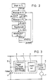
- the process sequence for operating the heating device according to the invention is shown schematically, specifying selected temperatures in the heat transfer circuit.
- the heater is always started in the partial load mode TL and even after the control break has elapsed, the heater is restarted in the partial load mode TL.
- This procedure allows thermal loads on the heater to be avoided when starting and after the control break, the design also being such that when there is a relatively large heat requirement, a switch to the next higher or the highest load level, the relatively quickly Full-load operation VL is carried out, so that the greatest possible heating power is generated in full-load operation VL in a relatively short time after the start of the heater, starting from the partial-load operation TL, and thus, for example, the passenger compartment of a vehicle is quickly heated up if the heater operated according to the invention is a vehicle heater.
- the control device is denoted overall by 1. As shown, it comprises a logic part 2 and a trigger circuit 3, which is intended for the switching thresholds and which contains an analog / digital (A / D) converter.
- the temperature of the heat transfer medium for example the water temperature in the case of a liquid heat transfer medium, is used as a guide variable in the example shown if the heater is a so-called water heater.
- a temperature sensor 4 is provided, the output of which at the input of the trigger circuit 3 below Interposition of the A / D converter is present.
- the queries regarding the switching thresholds are then carried out via the logic part 2.
- the control device 1 controls the heater, not shown, to the procedure described above.
- a ballast resistor is shown on the temperature sensor 4, which is arranged between the positive pole and the node between the output of the temperature sensor 4 and the input of the trigger circuit 3.
- the output of the control device 1 is applied to an actuator 6, via which, for example, the control of a combustion air blower motor 7 takes place.
- the design is such that the heater is always started in part-load operation TL and that a further temperature threshold is introduced in the process sequence, which switches from part-load operation TL to full-load operation VL if this switching threshold is undershot, since in the meantime there has been a higher heat requirement in the heat transfer circuit.
- the invention is not limited to the example explained above, but instead of the two load states described there, such as partial load TL and full load VL, of course, more heating output levels can also be implemented, if appropriate, the design then being such that the heater is always started in the lower heating output level or the lowest heating output level and then, if necessary, a switchover to the next higher heating output level is carried out.
Landscapes
- Engineering & Computer Science (AREA)
- Mechanical Engineering (AREA)
- Physics & Mathematics (AREA)
- Thermal Sciences (AREA)
- Chemical & Material Sciences (AREA)
- Combustion & Propulsion (AREA)
- General Engineering & Computer Science (AREA)
- Air-Conditioning For Vehicles (AREA)
- Control Of Combustion (AREA)
- Regulation And Control Of Combustion (AREA)
- Control Of Temperature (AREA)
- Control Of Resistance Heating (AREA)
Applications Claiming Priority (2)
| Application Number | Priority Date | Filing Date | Title |
|---|---|---|---|
| DE3822899 | 1988-07-06 | ||
| DE3822899A DE3822899A1 (de) | 1988-07-06 | 1988-07-06 | Verfahren zum betreiben eines heizgeraets und heizgeraet |
Publications (2)
| Publication Number | Publication Date |
|---|---|
| EP0349737A2 true EP0349737A2 (fr) | 1990-01-10 |
| EP0349737A3 EP0349737A3 (fr) | 1990-09-26 |
Family
ID=6358096
Family Applications (1)
| Application Number | Title | Priority Date | Filing Date |
|---|---|---|---|
| EP19890108665 Withdrawn EP0349737A3 (fr) | 1988-07-06 | 1989-05-13 | Procédé pour commander un appareil de chauffage et appareil de chauffage |
Country Status (5)
| Country | Link |
|---|---|
| EP (1) | EP0349737A3 (fr) |
| JP (1) | JPH0257820A (fr) |
| KR (1) | KR900002040A (fr) |
| CN (1) | CN1039479A (fr) |
| DE (1) | DE3822899A1 (fr) |
Cited By (5)
| Publication number | Priority date | Publication date | Assignee | Title |
|---|---|---|---|---|
| DE4309934A1 (de) * | 1993-03-26 | 1994-09-29 | Stiebel Eltron Gmbh & Co Kg | Verfahren zum Einleiten eines Bennvorgangs |
| WO1998020281A1 (fr) * | 1996-11-02 | 1998-05-14 | J. Eberspächer Gmbh & Co. | Bruleur a pulverisation sous pression pour systeme de chauffage automobile independant du moteur |
| EP1936274A3 (fr) * | 2006-12-12 | 2010-01-13 | J. Eberspächer GmbH Co. KG | Appareil de chauffage pour véhicule et procédé de démarrage du fonctionnement d'un appareil de chauffage pour véhicule |
| DE102009005639B4 (de) * | 2009-01-22 | 2016-07-14 | Eberspächer Climate Control Systems GmbH & Co. KG | Verfahren zum Regeln der Heizleistung eines Fahrzeugheizgerätes |
| CN109838808A (zh) * | 2019-03-26 | 2019-06-04 | 广东万和新电气股份有限公司 | 热负荷调节装置及全预混燃气热水器 |
Families Citing this family (6)
| Publication number | Priority date | Publication date | Assignee | Title |
|---|---|---|---|---|
| DE4014185A1 (de) * | 1990-05-03 | 1991-11-07 | Webasto Ag Fahrzeugtechnik | Verfahren zum betreiben eines mit fluessigbrennstoff gespeisten brenners |
| DE4139886C2 (de) * | 1991-12-04 | 1995-03-16 | Webasto Ag Fahrzeugtechnik | Wärmeträgerkreislauf eines Fahrzeuges |
| DE19523905A1 (de) * | 1995-06-30 | 1997-01-02 | Webasto Thermosysteme Gmbh | Fahrzeug mit einem motorunabhängigen Heizgerät |
| DE102007007122A1 (de) * | 2007-02-13 | 2008-08-14 | J. Eberspächer GmbH & Co. KG | Verfahren zum Betreiben eines Fahrzeugheizgerätes |
| DE102009044608A1 (de) * | 2009-11-20 | 2011-05-26 | Webasto Ag | Heizgerät |
| DE102009054621B4 (de) * | 2009-12-14 | 2021-02-11 | Eberspächer Climate Control Systems GmbH | Verfahren zum Betreiben eines Heizsystems, insbesondere für ein Fahrzeug oder Gebäude, und Heizsystem |
Family Cites Families (6)
| Publication number | Priority date | Publication date | Assignee | Title |
|---|---|---|---|---|
| CH476259A (de) * | 1967-04-14 | 1969-07-31 | Muff Franz | Einrichtung mit einem Ölbrenner der Schalenbauart |
| AT350409B (de) * | 1977-07-15 | 1979-05-25 | Leinfellner Helmut Ing | Regelgeraet fuer die heizleistung von mineraloel- oder gasverbrennenden heizgeraeten, vorzugsweise fuer den betrieb in kraftfahrzeugen |
| JPS6071819A (ja) * | 1983-09-28 | 1985-04-23 | Hitachi Ltd | 熱源機の運転方法 |
| US4638942A (en) * | 1985-12-02 | 1987-01-27 | Carrier Corporation | Adaptive microprocessor control system and method for providing high and low heating modes in a furnace |
| JPS63113221A (ja) * | 1986-10-29 | 1988-05-18 | Isuzu Motors Ltd | 暖房器の燃焼制御装置 |
| US4716858A (en) * | 1986-12-18 | 1988-01-05 | Honeywell Inc. | Automatic firing rate control mode means for a boiler |
-
1988
- 1988-07-06 DE DE3822899A patent/DE3822899A1/de not_active Withdrawn
-
1989
- 1989-05-13 EP EP19890108665 patent/EP0349737A3/fr not_active Withdrawn
- 1989-07-03 JP JP1171739A patent/JPH0257820A/ja active Pending
- 1989-07-05 CN CN89104548A patent/CN1039479A/zh active Pending
- 1989-07-06 KR KR1019890009657A patent/KR900002040A/ko not_active Withdrawn
Cited By (7)
| Publication number | Priority date | Publication date | Assignee | Title |
|---|---|---|---|---|
| DE4309934A1 (de) * | 1993-03-26 | 1994-09-29 | Stiebel Eltron Gmbh & Co Kg | Verfahren zum Einleiten eines Bennvorgangs |
| WO1998020281A1 (fr) * | 1996-11-02 | 1998-05-14 | J. Eberspächer Gmbh & Co. | Bruleur a pulverisation sous pression pour systeme de chauffage automobile independant du moteur |
| US6164554A (en) * | 1996-11-02 | 2000-12-26 | J. Eberspacher Gmbh & Co. | Pressure atomizing type burner for an engine independent heating system in a vehicle |
| EP1936274A3 (fr) * | 2006-12-12 | 2010-01-13 | J. Eberspächer GmbH Co. KG | Appareil de chauffage pour véhicule et procédé de démarrage du fonctionnement d'un appareil de chauffage pour véhicule |
| DE102009005639B4 (de) * | 2009-01-22 | 2016-07-14 | Eberspächer Climate Control Systems GmbH & Co. KG | Verfahren zum Regeln der Heizleistung eines Fahrzeugheizgerätes |
| CN109838808A (zh) * | 2019-03-26 | 2019-06-04 | 广东万和新电气股份有限公司 | 热负荷调节装置及全预混燃气热水器 |
| CN109838808B (zh) * | 2019-03-26 | 2024-06-11 | 广东万和新电气股份有限公司 | 热负荷调节装置及全预混燃气热水器 |
Also Published As
| Publication number | Publication date |
|---|---|
| CN1039479A (zh) | 1990-02-07 |
| JPH0257820A (ja) | 1990-02-27 |
| EP0349737A3 (fr) | 1990-09-26 |
| DE3822899A1 (de) | 1990-01-11 |
| KR900002040A (ko) | 1990-02-28 |
Similar Documents
| Publication | Publication Date | Title |
|---|---|---|
| DE2847097C2 (de) | Vorglühsystem zur Erleichterung des Kaltstarts eines Dieselmotors | |
| DE19728814A1 (de) | Kühlanlage für einen Verbrennungsmotor eines Kraftfahrzeuges | |
| DE3517953A1 (de) | Verfahren und schaltanordnung zum regeln der heizleistung einer heizeinrichtung | |
| DE3007129C2 (fr) | ||
| DE68910709T2 (de) | Abtauverfahren eines Kältemittelkreislaufs zur Anwendung in einem Kühlwagen. | |
| EP0349737A2 (fr) | Procédé pour commander un appareil de chauffage et appareil de chauffage | |
| DE2913101C2 (de) | Glühkerzen-Temperatursteuerschaltung | |
| EP0315934B1 (fr) | Méthode pour le réglage de la température des bougies dans un moteur diesel et circuit pour la réalisation de la méthode | |
| DE4239834B4 (de) | Vorwärmeinrichtung für einen wassergekühlten Kraftfahrzeugmotor mit externem Heizgerät | |
| DE2743059A1 (de) | Verfahren und anordnung zum schnellaufheizen von gluehkerzen | |
| WO2006066713A1 (fr) | Systeme et procede pour reguler la temperature d'une huile moteur dans un moteur a combustion interne d'un vehicule automobile | |
| DE19605216C5 (de) | Verfahren zum Betreiben eines Fahrzeugzusatzheizgerätes und Glüheinrichtung | |
| EP1279829B1 (fr) | Méthode et dispositif de commande du chauffage de bougies à incandescence pour un moteur Diesel | |
| DE19601772C2 (de) | Verfahren zum Starten eines Fahrzeugzusatzheizgerätes | |
| DE4106205A1 (de) | Steuervorrichtung fuer ein fahrzeug zur steuerung einer darin angebrachten einrichtung | |
| EP2059739B1 (fr) | Appareil frigorifique comportant un évaporateur à ventilation forcée | |
| DE2750464C2 (de) | Kontrolleinrichtung für die Glühkerzen einer luftverdichtenden Brennkraftmaschine | |
| DE102011003273B4 (de) | Verfahren zum Betreiben eines Heizsystems in einem Fahrzeug, insbesondere in einem Standheizungsbetriebsmodus | |
| DE19901807C1 (de) | Verfahren zum Betreiben eines Fahrzeug-Zusatzheitzgeräts | |
| DE10024448C1 (de) | Verfahren zum Steuern eines Heizwasserkreislaufs in einem Fahrzeug | |
| DE3110502C2 (de) | Durchlauferhitzer zur Vorwärmung von viskosem Brennstoff für eine Heizeinrichtung | |
| DE4328715C2 (de) | Brennkraftmaschine | |
| EP0688942A1 (fr) | Dispositif de refroidissement pour moteur à combustion interne refroidi par liquide d'un véhicule automobile | |
| EP0069967A1 (fr) | Dispositif pour allumer des lampes fluorescentes | |
| DE19607854A1 (de) | Heizgerät und Verfahren zur Regelung eines Heizgerätes |
Legal Events
| Date | Code | Title | Description |
|---|---|---|---|
| PUAI | Public reference made under article 153(3) epc to a published international application that has entered the european phase |
Free format text: ORIGINAL CODE: 0009012 |
|
| AK | Designated contracting states |
Kind code of ref document: A2 Designated state(s): DE FR GB SE |
|
| PUAL | Search report despatched |
Free format text: ORIGINAL CODE: 0009013 |
|
| AK | Designated contracting states |
Kind code of ref document: A3 Designated state(s): DE FR GB SE |
|
| STAA | Information on the status of an ep patent application or granted ep patent |
Free format text: STATUS: THE APPLICATION IS DEEMED TO BE WITHDRAWN |
|
| 18D | Application deemed to be withdrawn |
Effective date: 19910327 |