EP0349523A2 - Dispositif de séparation du laitier de l'acier - Google Patents
Dispositif de séparation du laitier de l'acier Download PDFInfo
- Publication number
- EP0349523A2 EP0349523A2 EP89890173A EP89890173A EP0349523A2 EP 0349523 A2 EP0349523 A2 EP 0349523A2 EP 89890173 A EP89890173 A EP 89890173A EP 89890173 A EP89890173 A EP 89890173A EP 0349523 A2 EP0349523 A2 EP 0349523A2
- Authority
- EP
- European Patent Office
- Prior art keywords
- inlet part
- slag
- collecting chamber
- separator
- collecting
- Prior art date
- Legal status (The legal status is an assumption and is not a legal conclusion. Google has not performed a legal analysis and makes no representation as to the accuracy of the status listed.)
- Withdrawn
Links
Images
Classifications
-
- C—CHEMISTRY; METALLURGY
- C21—METALLURGY OF IRON
- C21C—PROCESSING OF PIG-IRON, e.g. REFINING, MANUFACTURE OF WROUGHT-IRON OR STEEL; TREATMENT IN MOLTEN STATE OF FERROUS ALLOYS
- C21C7/00—Treating molten ferrous alloys, e.g. steel, not covered by groups C21C1/00 - C21C5/00
-
- C—CHEMISTRY; METALLURGY
- C21—METALLURGY OF IRON
- C21C—PROCESSING OF PIG-IRON, e.g. REFINING, MANUFACTURE OF WROUGHT-IRON OR STEEL; TREATMENT IN MOLTEN STATE OF FERROUS ALLOYS
- C21C5/00—Manufacture of carbon-steel, e.g. plain mild steel, medium carbon steel or cast steel or stainless steel
- C21C5/56—Manufacture of steel by other methods
- C21C5/562—Manufacture of steel by other methods starting from scrap
-
- B—PERFORMING OPERATIONS; TRANSPORTING
- B22—CASTING; POWDER METALLURGY
- B22D—CASTING OF METALS; CASTING OF OTHER SUBSTANCES BY THE SAME PROCESSES OR DEVICES
- B22D1/00—Treatment of fused masses in the ladle or the supply runners before casting
-
- C—CHEMISTRY; METALLURGY
- C21—METALLURGY OF IRON
- C21C—PROCESSING OF PIG-IRON, e.g. REFINING, MANUFACTURE OF WROUGHT-IRON OR STEEL; TREATMENT IN MOLTEN STATE OF FERROUS ALLOYS
- C21C7/00—Treating molten ferrous alloys, e.g. steel, not covered by groups C21C1/00 - C21C5/00
- C21C7/0087—Treatment of slags covering the steel bath, e.g. for separating slag from the molten metal
-
- Y—GENERAL TAGGING OF NEW TECHNOLOGICAL DEVELOPMENTS; GENERAL TAGGING OF CROSS-SECTIONAL TECHNOLOGIES SPANNING OVER SEVERAL SECTIONS OF THE IPC; TECHNICAL SUBJECTS COVERED BY FORMER USPC CROSS-REFERENCE ART COLLECTIONS [XRACs] AND DIGESTS
- Y02—TECHNOLOGIES OR APPLICATIONS FOR MITIGATION OR ADAPTATION AGAINST CLIMATE CHANGE
- Y02P—CLIMATE CHANGE MITIGATION TECHNOLOGIES IN THE PRODUCTION OR PROCESSING OF GOODS
- Y02P10/00—Technologies related to metal processing
- Y02P10/20—Recycling
Definitions
- the invention relates to a device for separating slag and steel in continuous metal melting processes.
- the outflowing steel which is only slightly overheated, has to be heated by adding metals which undergo exothermic reactions with the FeO content of the slag.
- this steel heating which takes place via heated slags, is cost-intensive since it is preferably carried out by adding FeSi or Al, although an improvement in the yield can be achieved by partially reducing the FeO of the slag.
- the invention now aims to provide a device of the type mentioned at the outset in which the collection of the melt can be carried out more economically and more simply by a continuous metal melting process, in particular a KVA process.
- the invention aims to enable the bath to overheat without having to operate the melting process at higher temperatures and without causing excessive heating of the slag as a result of the bath overheating.
- the device according to the invention essentially consists in that a separator separate from the melting vessel is arranged between a collecting pan and the tapping opening of the melting vessel, the inlet part of which is connected to the tapping opening of the melting vessel, in particular arranged below the tapping opening, that the inlet part is through a wall immersed in the separator, in particular a fox, is separated from a collecting chamber for the weld pool and has a slag drain such that the lower edge of the wall or fox in the inlet part is lower than the slag outlet on the inlet part, that the collecting chamber has a tap opening or has a drain for the molten bath and that at least part of the collection chamber is equipped with heating devices.
- a separator separate from the melting vessel and collecting pan creates a buffer space in which bath and slag can be collected during the pan change, and the fact that the separator itself has an inlet part and a collection chamber separated from the inlet part by a wall immersed in the separator, in particular a fox, perform the overheating of the bath in such a way that excessive heating of the slag is avoided.
- the design is such that at least a part of the collecting chamber is equipped with heating devices, with the lower edge of the wall immersed in the separator, in particular the fox, lower than the slag drain at the inlet part, providing a safe separation from Slag and bath is achieved.
- the wall immersed in the separator can be designed in a particularly simple manner as a fox, but designs are also readily possible in which the inlet part and the collecting chamber are formed separately from one another and are only connected to one another by an overflow channel.
- the design can be such that the inlet part is designed as a special chamber with refractory lining, that the wall immersed in the separator is formed by a wall of this chamber that is open near the bottom, and that a channel, in particular, is connected to this bottom-opening a channel having a conveyor is connected, which connects the inlet part to the collecting chamber for the molten pool.
- the overflow channel can thus be designed as a trough or have a conveyor to reduce the overall height, so that the conveyor trough can also run obliquely upwards.
- the design is such that the collecting chamber for the molten bath has a connection for a floor flushing, the connection for the floor flushing preferably being provided in the region of inductive heating of the collecting chamber.
- the design can be made in a particularly advantageous manner so that the inlet part has a height , which essentially corresponds to the immersion depth of the wall or the fox, has a cooling device for the refractory lining.
- the inlet part has a height , which essentially corresponds to the immersion depth of the wall or the fox, has a cooling device for the refractory lining.
- the dimensioning can be such that the inlet part can hold about 10 to 50% of the batch weight, whereas the heated area of the collecting chamber can contain about 10 to 50% of the batch weight.
- the collecting vessel can be oversized in such a way that the part of the melt entering during the pan change can be safely accommodated in the collecting vessel.
- the pan and the inlet section can be largely emptied before a pan change in order to provide the required buffer space for the pan change.
- the conveyor device can be designed as an electromagnetic climbing channel when an upwardly extending channel to the collecting chamber for the weld pool is arranged.
- the conveying capacity can be changed at short notice and, for example, to achieve a buffer space when changing the ladle, the conveying capacity of the electromagnetic climbing channel can be briefly increased immediately before changing the ladle, in order to make the required buffer volume available in the inlet part.
- the design can advantageously be made such that the burner is arranged near the outlet for the bath burner in the inlet part above the slag bath and / or in the collection chamber.
- the drain for the melt pool can also be advantageous to design the drain for the melt pool to be closable, for which purpose conventional devices, for example a slide closure, can be arranged.
- the design is advantageously made such that a winding device for Al wire opens into the inlet part, so that bath calming in the inlet part can be achieved.
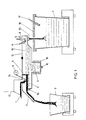
- FIG. 1 shows a first embodiment of a device according to the invention for separating slag and steel in continuous metal melting processes
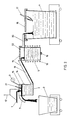
- 2 shows a modified embodiment of a device according to the invention, the inlet part being separated from the collecting chamber
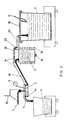
- 3 shows a further embodiment of the inventions device according to the invention, in which a collecting pocket is provided as the inlet part
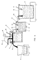
- FIG. 4 shows a modified embodiment of the device according to the invention with a siphon part between the inlet part and the collecting chamber.
- 1 denotes a steel / slag mixture which flows into the collecting part or inlet part 2.
- the metal / slag mixture is separated by the difference in density and the slag flows continuously as an overflow into a slag bucket 3.
- a catch pan 4 is shown in FIG. 1, into which the steel bath flows continuously.
- the separator of the design according to FIG. 1 consists of a superheater part 5, which is separated from the inlet part 2 by a fox 6.
- the fox 6 or the wall arranged in the separator between the inlet part 2 and the superheater part 5 prevents slag which is discharged into the slag bucket 3 via a continuous slag tapping 7 from getting into the superheater part 5.
- a tapping part which can be closed with a stopper 8 adjoins the superheater part 5 of the separator.
- an aluminum wire winding system 9 is provided, which can wind aluminum wire at a preselectable speed continuously or, if required, to calm the cooking reaction .
- a bottom flush 10 is provided in the superheater part or the collecting chamber 5 in order to ensure a sufficiently strong bath flow, which is important for an even heat distribution.
- a burner 11 is provided in order to be able to maintain a corresponding temperature in the area of the plug closure 8.
- the separate device is indicated at 12 in FIG. 1, in which the continuous melting process from which the flowing metal / slag stream 1 is continuously drawn off is carried out.
- the separator consisting of the inlet part 2 and the superheater part 5 is covered by a cover 13.
- cooling of the refractory material of the slag zone including the fox 6 is indicated at 14.
- the entire separator is designated by 15 in FIG.
- the collecting pan 4 has a lid 16 and a burner 17, as is indicated schematically.
- the superheater part 5 is heated by an induction furnace, indicated schematically by 18.
- the performance of this induction furnace is dimensioned so that the maximum amount flowing through can be heated by 80 to 100 ° C.
- the continuous tapping is closed for a while with the stopper or slide 8.
- the separator 15 is designed so that the continuous melting process does not have to be interrupted since there is still a reserve volume for the continuously flowing metal / slag mixture until the slag overflow is reached.
- This reserve volume is designed so that there is a reserve of 60 t, for example, until the rack has to be opened again. It is also advantageous to carry out the continuous steel tapping in such a way that a certain amount of steel, approx. 10% of the tapping weight, immediately flows into the collecting pan at the start of tapping, since this creates the risk of shells education is significantly reduced.
- the surface is additionally heated with the natural gas oxygen burner 11 in order to avoid bearings.
- the entire separator 15 is closed with a bricked cover in order to keep heat losses through radiation low. Except for the cooled slag area of the inlet part, the separator 15 is insulated against heat loss with well-insulating platelets behind the continuous feed. For repairing or relining separator parts, including the induction part, the entire separator 15 can be raised and lowered, extended and tilted. If the melting process is interrupted for a long time, the separator 15 is tipped out and moved to its heating position. Before recommissioning, scrap is charged and melted outside into the induction furnace or the collecting chamber 5, for which purpose the hinged lid 13 is opened, so that the induction furnace is filled with liquid steel into the separator. The opening under the fox 6 is closed with a refractory plate, which breaks through after a short time and allows the first portion of metal / slag to flow from the inlet part into the superheater part.
- This measure prevents slag from entering the induction furnace part, and after a short time, when the lower edge of the fox 6 is reached, no more slag flows from the inlet part 2 into the rest of the separator.
- the slag which initially flowed into the superheater part 3 of the separator 15 is inactivated and stiffened using reducing agents.
- the inlet part 2 is designed as a separate chamber and is separated from the collecting chamber 5, which in turn is heated by the induction furnace 18.
- a side wall of the separate inlet chamber 2 is provided for separating the slag from the metal bath.
- An electromagnetic climbing channel 19 is provided for connecting the inlet part 2 to the collecting chamber or the superheater part 5.
- the outflow for the metal bath of the superheater part is designated 20.
- the inlet part 2 is a refractory, capped vessel, the refractory lining of which is cooled in the area of the slag zone in order to keep the FeO of the slag from attacking the infeed.
- the floating slag is continuously discharged into the slag bucket 3 with the same amount of steel production and removal in the time unit, for example via the climbing channel 19 into the collecting chamber, via an overflow 7.
- Al wire can be wound into the inlet part via a wire winding device 9 in order to contain undesirable cooking reactions in the inlet part.
- a lid burner 21 is provided to preheat the vessel and the contents, especially at the start of melting.
- the inlet section can hold 15-20% of the batch weight. The degree of filling of the inlet part is adjusted by controlling the quantity conveyed via the climbing channel 19.
- the electromagnetic climbing channel 19 conveys the metal from the bottom of the inlet part 2 in an increase of 15 ° into the inductor part or the collecting chamber 5 of the separator 15. With it, the amount of the metal conveyed is matched to the incoming metal / slag mixture.
- the outlet of the electromagnetic climbing channel 19 opens into the inductor or the collecting chamber 5 of the separator 15.
- the inductor is equipped with a cover 22 to reduce the radiation losses. It has a channel drain 20 radially opposite the inlet part of the electromagnetic climbing channel 19, via which the steel flows into the collecting pan 4.
- the inductor is designed in such a way that it contains 10 - 50% of the batch weight and can overheat by 80 - 100 ° with the performance of the melting unit.
- the collecting pan which is provided with a cover 16 with a burner 17 to avoid radiation losses, takes up the amount predetermined for the further processing of the metal.
- the inlet part 2 of the separator 15 is largely emptied before the tapping via an additional conveying of steel compared to the incoming amount of steel of the electromagnetic climbing channel 19, so that sufficient time passes until it returns to the superheater part or the Collection chamber 5 must be promoted so that a pan change can take place in the meantime.
- the superheater part 5 has an unheated section for buffering in the upper part.
- the electromagnetic climbing channel 19 is no longer necessary for the forced removal of steel from the inlet part 2, for the possibility of buffering.
- the inlet part 2 is formed separately from the superheater part or the collecting chamber 5, wherein in FIG. 3 the inlet part is designed as a collection pocket which receives the continuously flowing metal / slag mixture and which is directly connected to the electromagnetic climbing channel 19 is flanged.
- This inlet part designed as a collecting pocket, in turn has a slag overflow 7, via which the slag, which cannot be transported by the electromagnetic climbing channel 19, runs off continuously.
- the inlet part 2 is again formed in the area of the slag drain with a cooling 14 for the lining in order to keep the slag attack low.
- a part of the side wall separating the inlet part 2 from the climbing channel 19 is again provided as the wall immersing in the inlet part 2.
- an Al wire winding machine 9 is provided, by means of which Al wire can be wound continuously or as required to calm cooking reactions in the collecting pocket or the inlet part 2.
- the electromagnetic climbing channel 19 transports the only slightly overheated steel with an inclination of 15 ° into the superheater part 5, which is heated inductively, and which is equipped with the inert gas purging 10 for mixing the steel.
- the superheated metal flows continuously from the superheater part 5, which is designed in such a way that the metal flowing in in the meantime can be overheated by 80-100 °, into a capped, highly preheated collecting pan 4.
- the lid 16 of this collecting pan is in turn covered with a natural gas / Oxygen burner 17 provided so that the pan 4 can be heated even during filling.
- the continuous outflow 20 into the collecting is via a slide closure 23 pan 4 interrupted and the incoming steel buffered in the upper part of the superheater 5 during this changing time.
- the buffer volume is designed so that for a given output approx. 5 min. Steel can be continuously conveyed via the climbing channel 19 into the superheater 5.
- the pan change takes place during this time. In order to avoid the formation of shells in the base region of the pan 4, it is favorable if a certain amount flows in suddenly at the beginning of the continuous pan filling process, which is the case with the inventive concept.
- the inlet part 2 is again formed separately from the superheater part or the collecting chamber 5 and the inlet part 2 in turn has a slag outflow 7, via which slag flows continuously into a slag pan.
- the cooling 14 in the area of the slag zone is again indicated to prevent excessive wear of the lining of the inlet part 2 in this area.
- 6 in turn denotes a fox protruding into the inlet part 2, this fox being designed as a water-cooled siphon part, via which the metal bath is transferred from the inlet part 2 into the superheater part or the collecting chamber 5 with the induction furnace indicated by 18.
- the cover 22 of the collecting chamber 5 has a burner 24, just as a burner 21 is provided in the cover of the inlet part 2.
- a slide closure 23 is provided in the drain 20 of the collecting chamber 5 as in the previous embodiment.
- the inflowing metal is overheated in the superheater part 5 by 80-100.degree. C., in which case a floor flushing 10 with inert gas is also provided.
- the inlet part 2 and the superheater part 5 can have a volume similar to the embodiment according to FIG. 2 in order to enable the pan 4 to be replaced in a suitable manner by forming a sufficient buffer volume.
Landscapes
- Chemical & Material Sciences (AREA)
- Engineering & Computer Science (AREA)
- Materials Engineering (AREA)
- Metallurgy (AREA)
- Organic Chemistry (AREA)
- Manufacturing & Machinery (AREA)
- Analytical Chemistry (AREA)
- Mechanical Engineering (AREA)
- Vertical, Hearth, Or Arc Furnaces (AREA)
- Gasification And Melting Of Waste (AREA)
- Furnace Details (AREA)
- Refinement Of Pig-Iron, Manufacture Of Cast Iron, And Steel Manufacture Other Than In Revolving Furnaces (AREA)
Applications Claiming Priority (2)
| Application Number | Priority Date | Filing Date | Title |
|---|---|---|---|
| AT1667/88 | 1988-06-27 | ||
| AT0166788A AT394732B (de) | 1988-06-27 | 1988-06-27 | Vorrichtung zum trennen von schlacke und stahl |
Publications (2)
| Publication Number | Publication Date |
|---|---|
| EP0349523A2 true EP0349523A2 (fr) | 1990-01-03 |
| EP0349523A3 EP0349523A3 (fr) | 1990-04-04 |
Family
ID=3518383
Family Applications (1)
| Application Number | Title | Priority Date | Filing Date |
|---|---|---|---|
| EP89890173A Withdrawn EP0349523A3 (fr) | 1988-06-27 | 1989-06-21 | Dispositif de séparation du laitier de l'acier |
Country Status (11)
| Country | Link |
|---|---|
| EP (1) | EP0349523A3 (fr) |
| JP (1) | JPH0247214A (fr) |
| KR (1) | KR900000143A (fr) |
| CN (1) | CN1039651A (fr) |
| AT (1) | AT394732B (fr) |
| BR (1) | BR8903117A (fr) |
| DD (1) | DD288178A5 (fr) |
| HU (1) | HU205291B (fr) |
| IN (1) | IN171153B (fr) |
| YU (1) | YU128489A (fr) |
| ZA (1) | ZA894351B (fr) |
Families Citing this family (11)
| Publication number | Priority date | Publication date | Assignee | Title |
|---|---|---|---|---|
| US5114205A (en) * | 1991-07-12 | 1992-05-19 | Jee Elwood Y | Vehicular air deflector |
| ZA978026B (en) * | 1996-09-17 | 1998-03-03 | Holderbank Financ Glarus | Process for working up combustion residues. |
| AT403927B (de) * | 1996-09-17 | 1998-06-25 | Holderbank Financ Glarus | Verfahren zum aufarbeiten von verbrennungsrückständen |
| KR20020049897A (ko) * | 2000-12-20 | 2002-06-26 | 이구택 | 용융슬래그 분배장치 |
| KR100843835B1 (ko) * | 2001-11-23 | 2008-07-03 | 주식회사 포스코 | 슬래그 포트의 슬래그 분리장치 |
| CN101239384B (zh) * | 2007-02-06 | 2010-05-19 | 宝山钢铁股份有限公司 | 铸余渣和钢水的分离方法 |
| CN108393482A (zh) * | 2017-02-05 | 2018-08-14 | 鞍钢股份有限公司 | 一种铁水无污染电磁聚渣方法 |
| CN110629040B (zh) * | 2019-10-17 | 2021-10-01 | 常州大学 | 一种从高铝锌渣中回收低铁含量合金液的装置及方法 |
| CN111074022A (zh) * | 2019-12-04 | 2020-04-28 | 西安交通大学 | 一种液态熔渣缓存及流量控制装置的操作方法 |
| DE102021002170A1 (de) | 2021-04-26 | 2022-10-27 | Bluemetals GmbH | Pfanne mit speziellem Ausguss für einen metallurgischen Betrieb |
| CN120249593A (zh) * | 2025-06-04 | 2025-07-04 | 无锡东雄重型电炉有限公司 | 一种废钢再利用的精炼钢炉设备 |
Family Cites Families (10)
| Publication number | Priority date | Publication date | Assignee | Title |
|---|---|---|---|---|
| FR1418925A (fr) * | 1964-10-12 | 1965-11-26 | Siderurgie Fse Inst Rech | Procédé et dispositif pour l'affinage continu de la fonte en acier |
| FR2174769A2 (en) * | 1972-03-10 | 1973-10-19 | Air Liquide | Treatment of molten metal with solids - in appts ensuring a short time lapse between treatment and casting |
| SE360681B (fr) * | 1972-06-05 | 1973-10-01 | Graenges Essem Ab | |
| DE2325593C2 (de) * | 1973-05-19 | 1975-03-27 | Kloeckner-Werke Ag, 4100 Duisburg | Kontinuierliche Stahlerzeugung |
| US4095777A (en) * | 1976-11-15 | 1978-06-20 | Monsanto | Combustion chamber with slag dam and drain trough |
| DD236860A3 (de) * | 1978-06-28 | 1986-06-25 | Dso Cherna Metalurgia | Verfahren und vorrichtung fuer die raffination von eisenschmelzen |
| US4457777A (en) * | 1981-09-07 | 1984-07-03 | British Steel Corporation | Steelmaking |
| US4520310A (en) * | 1982-06-18 | 1985-05-28 | Sycon Corporation | Autofunction voltmeter |
| DE3231434C1 (de) * | 1982-08-20 | 1983-11-17 | Mannesmann AG, 4000 Düsseldorf | Verfahren und Vorrichtung zum Abtrennen von Schlacke |
| JPS6126762A (ja) * | 1984-07-16 | 1986-02-06 | Toho Aen Kk | ドロス排出装置 |
-
1988
- 1988-06-27 AT AT0166788A patent/AT394732B/de not_active IP Right Cessation
-
1989
- 1989-06-05 IN IN435/CAL/89A patent/IN171153B/en unknown
- 1989-06-08 ZA ZA894351A patent/ZA894351B/xx unknown
- 1989-06-21 EP EP89890173A patent/EP0349523A3/fr not_active Withdrawn
- 1989-06-22 YU YU01284/89A patent/YU128489A/xx unknown
- 1989-06-26 DD DD89329992A patent/DD288178A5/de not_active IP Right Cessation
- 1989-06-26 BR BR898903117A patent/BR8903117A/pt unknown
- 1989-06-26 CN CN89104444A patent/CN1039651A/zh active Pending
- 1989-06-27 KR KR1019890008851A patent/KR900000143A/ko not_active Ceased
- 1989-06-27 JP JP1165140A patent/JPH0247214A/ja active Pending
- 1989-06-27 HU HU893234A patent/HU205291B/hu not_active IP Right Cessation
Also Published As
| Publication number | Publication date |
|---|---|
| JPH0247214A (ja) | 1990-02-16 |
| HUT50069A (en) | 1989-12-28 |
| HU205291B (en) | 1992-04-28 |
| ATA166788A (de) | 1991-11-15 |
| ZA894351B (en) | 1990-02-28 |
| DD288178A5 (de) | 1991-03-21 |
| KR900000143A (ko) | 1990-01-30 |
| YU128489A (en) | 1991-10-31 |
| EP0349523A3 (fr) | 1990-04-04 |
| AT394732B (de) | 1992-06-10 |
| BR8903117A (pt) | 1990-03-20 |
| CN1039651A (zh) | 1990-02-14 |
| IN171153B (fr) | 1992-08-08 |
Similar Documents
| Publication | Publication Date | Title |
|---|---|---|
| AT394732B (de) | Vorrichtung zum trennen von schlacke und stahl | |
| DE2007081B2 (de) | Rinnenofen für Aluminium oder Magnesium enthaltende Schmelzen | |
| DE2944269C3 (de) | Ofengefäß eines kippbaren Lichtbogenofens | |
| DE19826085C2 (de) | Verfahren und Vorrichtung zum Abdichten einer Abstichöffnung in metallurgischen Gefäßen | |
| DE2406480A1 (de) | Verfahren zum raffinieren von stahl | |
| DE2411507C2 (de) | Feuerfest ausgekleidetes, kippbares Konvertergefäß zur Behandlung von Metallschmelzen | |
| EP0799323B1 (fr) | Unite metallurgique basculante constituee de plusieurs recipients | |
| DE69416863T2 (de) | Vorrichtung zum beschicken eines elektrofens mit flüssigmetall | |
| EP0160185B1 (fr) | Carcasse de four basculant métallurgique | |
| DE2325593C2 (de) | Kontinuierliche Stahlerzeugung | |
| DE3732939C2 (fr) | ||
| EP0252308A1 (fr) | Procédé de traitement de métaux liquides et dispositif pour la mise en oeuvre dudit procédé | |
| DE3334733C2 (de) | Verfahren und Anlage zum Herstellen von hochreinen Legierungen | |
| DE602004004159T2 (de) | Verfahren zum chargieren von feinkörnigen materialien in einen elektrolichtbogenofen | |
| EP0128965B1 (fr) | Procédé pour exploiter un four métallurgique de fusion et four métallurgique de fusion | |
| DE3722645C2 (fr) | ||
| DE3878507T2 (de) | Gefaess und verfahren zum behandeln von metallschmelzen. | |
| EP0188891B1 (fr) | Procédé de traitement des métaux liquides | |
| DE3221241C2 (de) | Verfahren und Vorrichtung zum Herstellen von gießfertigem Metall | |
| DE2135289A1 (fr) | ||
| CH299436A (de) | Anlage zum kontinuierlichen Giessen von hochschmelzenden Metallen. | |
| DE661703C (de) | Vorrichtung zum Trennen und Vergiessen hoeher schmelzender Metalle | |
| DE1558426A1 (de) | Verfahren und vorrichtung zur aufarbeitung von kupferkonzentraten | |
| DE1801131A1 (de) | Induktions-Tiegelofen | |
| EP0354897A1 (fr) | Procédé et installation pour réchauffage d'acier en fusion |
Legal Events
| Date | Code | Title | Description |
|---|---|---|---|
| PUAI | Public reference made under article 153(3) epc to a published international application that has entered the european phase |
Free format text: ORIGINAL CODE: 0009012 |
|
| AK | Designated contracting states |
Kind code of ref document: A2 Designated state(s): AT BE CH DE ES FR GB GR IT LI LU NL SE |
|
| PUAL | Search report despatched |
Free format text: ORIGINAL CODE: 0009013 |
|
| AK | Designated contracting states |
Kind code of ref document: A3 Designated state(s): AT BE CH DE ES FR GB GR IT LI LU NL SE |
|
| 17P | Request for examination filed |
Effective date: 19900514 |
|
| 17Q | First examination report despatched |
Effective date: 19901204 |
|
| STAA | Information on the status of an ep patent application or granted ep patent |
Free format text: STATUS: THE APPLICATION IS DEEMED TO BE WITHDRAWN |
|
| 18D | Application deemed to be withdrawn |
Effective date: 19910416 |