EP0348926A2 - Vorrichtung zum Verhindern des Reifenschlupfes und deren Fertigungsverfahren - Google Patents
Vorrichtung zum Verhindern des Reifenschlupfes und deren Fertigungsverfahren Download PDFInfo
- Publication number
- EP0348926A2 EP0348926A2 EP89111742A EP89111742A EP0348926A2 EP 0348926 A2 EP0348926 A2 EP 0348926A2 EP 89111742 A EP89111742 A EP 89111742A EP 89111742 A EP89111742 A EP 89111742A EP 0348926 A2 EP0348926 A2 EP 0348926A2
- Authority
- EP
- European Patent Office
- Prior art keywords
- tire
- arm
- preventing device
- reinforcement member
- slippage preventing
- Prior art date
- Legal status (The legal status is an assumption and is not a legal conclusion. Google has not performed a legal analysis and makes no representation as to the accuracy of the status listed.)
- Withdrawn
Links
- 238000004519 manufacturing process Methods 0.000 title claims description 13
- 230000002787 reinforcement Effects 0.000 claims abstract description 52
- 230000003014 reinforcing effect Effects 0.000 claims description 15
- 239000000463 material Substances 0.000 claims description 7
- 229920003002 synthetic resin Polymers 0.000 claims description 6
- 239000000057 synthetic resin Substances 0.000 claims description 6
- 229920005989 resin Polymers 0.000 claims description 4
- 239000011347 resin Substances 0.000 claims description 4
- 239000000543 intermediate Substances 0.000 claims 4
- 239000011248 coating agent Substances 0.000 claims 2
- 238000000576 coating method Methods 0.000 claims 2
- 229910000831 Steel Inorganic materials 0.000 description 13
- 239000010959 steel Substances 0.000 description 13
- 229920001169 thermoplastic Polymers 0.000 description 11
- 238000000465 moulding Methods 0.000 description 10
- 239000011162 core material Substances 0.000 description 8
- 239000002184 metal Substances 0.000 description 7
- 239000007924 injection Substances 0.000 description 6
- 238000002347 injection Methods 0.000 description 6
- 238000001746 injection moulding Methods 0.000 description 3
- 238000000034 method Methods 0.000 description 3
- 229920002430 Fibre-reinforced plastic Polymers 0.000 description 2
- 239000004677 Nylon Substances 0.000 description 2
- 239000011151 fibre-reinforced plastic Substances 0.000 description 2
- 238000007667 floating Methods 0.000 description 2
- 229920001778 nylon Polymers 0.000 description 2
- 229920000728 polyester Polymers 0.000 description 2
- -1 polyethylene Polymers 0.000 description 2
- 229920001187 thermosetting polymer Polymers 0.000 description 2
- 229920000049 Carbon (fiber) Polymers 0.000 description 1
- JOYRKODLDBILNP-UHFFFAOYSA-N Ethyl urethane Chemical compound CCOC(N)=O JOYRKODLDBILNP-UHFFFAOYSA-N 0.000 description 1
- 239000004698 Polyethylene Substances 0.000 description 1
- 239000004809 Teflon Substances 0.000 description 1
- 229920006362 Teflon® Polymers 0.000 description 1
- 239000004433 Thermoplastic polyurethane Substances 0.000 description 1
- 229920002978 Vinylon Polymers 0.000 description 1
- 238000005452 bending Methods 0.000 description 1
- 239000004917 carbon fiber Substances 0.000 description 1
- 238000010276 construction Methods 0.000 description 1
- 230000003467 diminishing effect Effects 0.000 description 1
- 229920001971 elastomer Polymers 0.000 description 1
- 238000002474 experimental method Methods 0.000 description 1
- 239000000835 fiber Substances 0.000 description 1
- 239000003365 glass fiber Substances 0.000 description 1
- 238000003780 insertion Methods 0.000 description 1
- 230000037431 insertion Effects 0.000 description 1
- 239000012528 membrane Substances 0.000 description 1
- VNWKTOKETHGBQD-UHFFFAOYSA-N methane Chemical compound C VNWKTOKETHGBQD-UHFFFAOYSA-N 0.000 description 1
- 230000002093 peripheral effect Effects 0.000 description 1
- 239000004033 plastic Substances 0.000 description 1
- 229920003023 plastic Polymers 0.000 description 1
- 229920000573 polyethylene Polymers 0.000 description 1
- 229920001155 polypropylene Polymers 0.000 description 1
- 229920002635 polyurethane Polymers 0.000 description 1
- 239000004814 polyurethane Substances 0.000 description 1
- 239000005060 rubber Substances 0.000 description 1
- 238000000926 separation method Methods 0.000 description 1
- 229920002725 thermoplastic elastomer Polymers 0.000 description 1
- 239000012815 thermoplastic material Substances 0.000 description 1
- 229920002803 thermoplastic polyurethane Polymers 0.000 description 1
Images


Classifications
-
- B—PERFORMING OPERATIONS; TRANSPORTING
- B29—WORKING OF PLASTICS; WORKING OF SUBSTANCES IN A PLASTIC STATE IN GENERAL
- B29C—SHAPING OR JOINING OF PLASTICS; SHAPING OF MATERIAL IN A PLASTIC STATE, NOT OTHERWISE PROVIDED FOR; AFTER-TREATMENT OF THE SHAPED PRODUCTS, e.g. REPAIRING
- B29C33/00—Moulds or cores; Details thereof or accessories therefor
- B29C33/12—Moulds or cores; Details thereof or accessories therefor with incorporated means for positioning inserts, e.g. labels
-
- B—PERFORMING OPERATIONS; TRANSPORTING
- B60—VEHICLES IN GENERAL
- B60C—VEHICLE TYRES; TYRE INFLATION; TYRE CHANGING; CONNECTING VALVES TO INFLATABLE ELASTIC BODIES IN GENERAL; DEVICES OR ARRANGEMENTS RELATED TO TYRES
- B60C27/00—Non-skid devices temporarily attachable to resilient tyres or resiliently-tyred wheels
- B60C27/02—Non-skid devices temporarily attachable to resilient tyres or resiliently-tyred wheels extending over restricted arcuate part of tread
- B60C27/04—Non-skid devices temporarily attachable to resilient tyres or resiliently-tyred wheels extending over restricted arcuate part of tread the ground-engaging part being rigid
Definitions
- the present invention relates to a tire slippage preventing a device applied to a tire of a vehicle running on a snow covered street or so and a method of manufacturing the same.
- a tire slippage preventing device of a type which is provided with a boss portion attached to the wheel of a tire and a plurality of arms radially extending from the boss portion, the respective end portions of the arms being contact with the surface of the tire which is contact with a road surface.
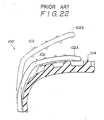
- an arm 102 is made of a flexible material like rubber or plastics and it is of a cantilever type. Accordingly, in case that an end portion 102A of the arm 102 is elongated so as to cover a tire 104 sufficiently and a vehicle equipped with the tire slippage preventing device thus constructed runs at a high speed, the end portion 102A of the arm 102 is floated away from the tire 104 due to a centrifugal force, as shown with an imaginary in Fig. 22. As a result, there is such a problem that the tip portion 102A of the arm 102 hits a fender (not shown in the figure) of the vehicle and might be damaged.
- the length of the end portion 102A is shortened to prevent the end portion 102A from floating.
- the arm 102 does not cover the tire 104 sufficiently, so that slippage of the tire 104 can not be prevented effectively, or in some cases it becomes impossible for the vehicle to run up a slope road.
- An object of the present invention is to provide a tire slippage preventing device in which the tip portion of an arm is not floated from a tire at the time when the tire is rotated at a high speed even though it is elongated, and a mathod of manufacture the same.
- a tire slippage preventing device provides with a base portion disposed on the side of a tire and at least one arm extending from the base portion and disposed to the outer periphery of tire.
- the tire slippage preventing device is also provided with a reinforcing member buried therein for preventing an end portion of the arm from separating largely from the outer periphery of the tire to a centrifugal force even when the tire slippage preventing device is equipped with the tire.
- At least one part of the reinforcement member is buried in the arm, and the reinforcement member resists such a deformation that the end portion of the arm is forced to separate from the outer periphery of the tire, so that the arm is prevented from a large deformation.
- a material having a high tensile strength, at least one part of which is buried in the arm, will be applicable as the reinforcement member.
- a cavity corresponding to the shape of an arm to be formed is provided in a mold for forming arm, and the cavity is filled with melt resin after a reinforcement member is disposed in the cavity.
- the arm formed in this way has the reinforcement member buried in it.
- the reinforcement member is secured to a pin protruded from the mold into the cavity to be positioned in the cavity so taht it is buried at a desired position in the cavity.
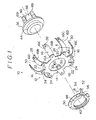
- Figs. 1 to 4 show a first embodiment of a tire slippage preventing device 10 according to the present invention.
- a tire slippage preventing device 10 in a tire slippage preventing device 10 its main body 12 is provided with a boss 14 and eight arms 16, each of which is made of a synthetic resin.
- These members may, for example, by made from thermoplastic elastomer, polyethylene, such thermoplastic plastics as thermoplastic polyurethane, FRP (fiber reinforced plastics), such thermosetting plastics as thermosetting polyurethane.
- the boss 14 which is disposed at a side of a tire, is provided with a disc portion 18 having a through hole 20 formed in its center and eight connecting portions for connecting the arms 16, which are formed integrally radially protruded from the outer periphery of the disc portion 18 at constant intervals.
- the arms 16 are connected at their base portion 16A to the connecting portions 22 by pins 24.
- Intermediate portions 16B of the arms 16 are bent, and end portions 16C thereof are extending in axial direction of the boss 14, they are disposed on a road contact surface of the tire.
- the arm 16 is flat and has a pin insertion hole 26 formed in the base portion 16A for inserting the pin 24.
- the end portion 16C of the arm 16 is forked in order to give the tire a better footing and improve a thrust on snow.
- a plurality of spike pins 28 are protruding from a road contact surface 16D of the end portion 16C of the arms 16. Further, a plurality of projections are protruding from a tire contact surface 16E of the end portions 16C of the arms 16.
- a thickness T of the arm 16 is set at 7 mm.
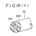
- the reinforcement member 32 of this embodiment is formed of a steel cord 32A with a diameter of 1.5 mm and a hollow cylindrical cover 32B covering the steel cord 32A.
- a pair of the reinforcement member 32 are buried along the longitudinal direction of the arm 16 and on both sides thereof.
- the cover 32B is of the same thermoplastic material as the arm 16 with a thickness of about 1 mm.
- the steel cord 32A and the cover 32B are glued together.
- such a core material for the reinforcement member 32 can be used as another metal cord, a organic fiber canvas (nylon, teflon, polyester, vinylon), a quebracord, a carbon fiber roving, thin metal membranes, a glass fiber cord, an amorphous cord ard the like.
- a core material for the reinforcement member 32 can be used as another metal cord, a organic fiber canvas (nylon, teflon, polyester, vinylon), a quebracord, a carbon fiber roving, thin metal membranes, a glass fiber cord, an amorphous cord ard the like.
- the steel cord 32A When the steel cord 32A is used, care has to be taken about its construction. For example, in the steel cord 32A having a structure where in the center of a plurality of strands 33A a core strand 33B is disposed, as shown in Fig. 16B, only the core strand 33B is liable to be early damaged due to flexion of the arm 16. Therefore, it is preferable, that as shown in Fig. 16(C), the steel cord 32A is made only of the strands 33A without the core strand 33B. As shown in Fig.
- the steel cord 32 has the core strand 33B made of a material having a lower elasticity, that is, a larger tensile strain, than steel, such as nylon, urethane, polypropylen, polyester and the like. Additionally, for improving fatigue resistance, a filament constituting the strand 33A or the core strand 33B should be extremely fine, for example, it is preferable that the filament has a diameter of 0.1 mm or less.
- the steel cord 32A may be constituted by only one core strand 33B having a large diameter, for example, a diameter of 1.5 mm, without the strands 33A of the steel cord 32A shown in Fig. 16(B).
- the only core strand 33B may be constituted by filaments each having a diameter of, for example, 0.3 mm.
- the reinforcement members 32 are buried in the arm 16 nearer to the tire contact surface 16E with respect to a center line K. It is ideal that, the reinforcement member 32 are respectively buried at a distance of 1/2D to 3D from the contact tire surface 16E, where D is the diameter of the reinforcement member.
- the reinforcement members 32 are respectively buried in a position of 1/2 D to 3 D away from both side surface of the arm 16 in a direction towards the center of the arm 16.
- each of the arms 16 is by an operation swingable around each of the pins 24 as a fulcrum in the direction of arrow A shown in Fig. 1.
- the tire slippage preventing device 10 is provided with a mounting device 36 for mounting the main body 12 to an tire assembly 34, and the mounting device 36 has a cylindrical attachment 38 made of a steel plate, a plurality of spring plate 40 fixed to the cylindrical attachment 38, and an end ring 42 removably secured to the attachment 38 and serving as a member for preventing the main body 12 from slipping off.
- Each of the spring plates 40 is formed at its tip portion with a connecting tooth 69 bent outward.
- the attachment 38 is folded several times so that it is formed with an annular projecting portion 44 at one end along the axial direction of the attachment 38 and with an annular recess portion 46 in an intermediate part therealong. the diameter of the projecting portion 44 is smaller than that of through hole 20 of the boss 14.
- the end ring 42 is provided with a C-shaped ring portion 48 which is open at one portion along its longitudinal direction and which has a substantially U-shaped sectional configuration corresponding to the annular projecting portion 44.
- the end ring 42 is also provided projectingly from the ring portion 48 with a flange portion 50 by bending.
- the end ring 42 is equipped with a buckle 52 that connects both ends of the ring portion 48.
- the buckle 52 is provided with a lever 54 pivotted at one end portion of the ring portion 48 and a link plate 56 rotatably supported at the other end portion of the ring portion 48, the other end portion of the ring plate 56 being pivotted to an intermediate portion of the lever 54.
- both the end portions of the ring portion 48 are pulled in the direction approaching to each other by a fraction force generated when the lever 54 is brought down in the direction of arrow B, thereby reducing the diameter of the end ring 42. Since the flange 50 is formed with cuts at regular intervals, the end ring 42 is not prevented from the diameter reduction movement.
- the diameter of the ring portion 48 in the condition that the diameter of the end ring 42 is reduced is slightly smaller than that of the annular projecting portion 44. Accordingly, when the ring portion 48 is wound around the annular projecting portion 44 and fixed to the attachment 38, the end ring 42 is constraint immovable by it's own elastic force. In this state, the outer diameter of the flange portion 50 is sufficiently larger than that of the through hole 20 of the boss 14.
- the tire assembly 34 equipped with the tire slippage preventing device arranged in the above manner includes a wheel 58 and a tire 60 fitted on the wheel 58.
- the wheel 58 is provided wiht a rim portion 62 fitted on the tire 60 and a disc portion 64 welded to the rim portion.
- the rim portion 62 is formed at an end portion of its lug portion and a bent portion of its intermediate portion with annular groove portions 66 and 68 respectively.
- the manufacture method for the arms 16 of the tire slippage preventing device is as follows:
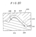
- a metal mold 200 which is applied to a horizontal injection molding machine for forming the arm 16 includes a first molding member 202 and a second molding member 204.
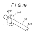
- the first molding member 202 is provided with a plurality of metallic supporting pins protruded into a cavity 206 formed in the first molding member 202 and injected with resin. These supporting pins 208 are disposed at positions corresponding to the position where the reinforcement member 32 is expected to be disposed. Moreover, the supporting pins are formed at their tip portions with forked engaging portions 208 with which the reinforcement member 32 is engaged.
- the first molding member 202 and the second molding member 204 are assembled and molten thermoplastic plastics is injected into the cavity 206 through an injection hole 210 formed between the first and second molding members 202 and 204.
- the arm 16 wiht the reinforcing member 32 in a predetermined position is formed.
- the reinforcing member 32 is held firmly by the supporting pins 208, the reinforcement member 32 is prevented from movement even though injection pressure is increased at the time of injection.
- the hollow cylindrical cover 32B of the reinforcing member 22 is also made from thermoplastic plastics, injection of thermoplastic plastics into the metal mold 200 will cause the hollow cylindrical cover 32B to melt, so that the hollow cylindrical cover 32B unites with the arm 16.
- thermoplastic plastics of the arm 16 and the thermoplastic plastics of the hollow cylindrical cover 32B are greater than the difference in hardness between the thermoplastic plastics of the arm 16 and the thermoplastic plastics of the hollow cylindrical cover 32B is, the better will be the adhesion therebetween.
- the supporting pins 208 are fixed in the first molding member portion 202.
- a pair of supporting pins set at a protruding length of about 3 mm and spaced at a mutual distance of about 4 mm so as to be able to support the reinforcement member 32 therebetween also be arranged as to be freely moved in and out of the cavity 206.
- the supporting pins are moved out of the pins, cavity 206 before the molten thermoplastic plastics injected is solidified, there are no holes corresponding to the supporting pins on the arm 16. Therefore, not only no cracks are likely to form radiating from the holes, but the external appearance of the arm 16 can be improved too.
- Fig. 18 shows the manufacturing method for the arm 16 where two reinforcement members 32 are disposed in the arm 16, but in the manufacturing method for the arm 16 according to the present invention may be applied to the case where one continuous reinforcement member 32 is disposed in the arm 16.
- Fig. 20 shows a metal mold 200 which is applied to a vertical injection molding machine.
- connecting the reinforcement member 32 to the supporting pins 208 is simpler than that in the case of the horizontal injection molding machine.
- the attachment 38 of the mounting device 36 is mounted to the wheel 58. This mounting is completed easily and simply by pushing the attachment 38 into the inner peripheral portion of the rim portion 62.
- the main body 12 of the tire slippage preventing device 10 is mounted on the attachment 38.
- the through hole 20 of the boss 14 is opposed to the attachment 38 and fitted to the same.
- the tire 60 of the vehicle has a broad contact area contacting to the ground because it is squeezed by the weight of the vehicle.
- adjacent two of the eight arms 16 to be disposed on both the sides of the broad contact area of the tire 60 is small in a distance therebetween, if they are, and it is difficult to dispose the tip portions of the end portions 16C of the adjacent two at predetermined positions on the tread portion of the tire 60.
- the adjacent two arms 16 are disposed so as to take the contact area of the tire 60 therebetween.
- the adjacent two arms 16 are swung around the pins 24 from the positions disposed above in the directions of separation from each other, so that they become disposed at the positions deviated from the predetermined positions along the circumferential direction of the tire 60 on the tread portion of the tire 60.
- the end ring 42 is mounted on the attachment 38.
- This mounting is conducted by such an operation that the side of the flange 50 is brought in opposition to the boss 14, the ring portion 48 is fitted around the annular protruding portion 44 in the condition that the lever 54 is not pushed down, and thereafter the lever 54 is pushed down.
- the end ring 42 is securely fixed to the attachment 38.
- the mounting operation of the fire slippage preventing device 10 is completed.
- the adjacent two arms 16 which have been swung around the pins 24 are natural swung back in a direction counter to the previous swinging direction to be disposed in the predetermined positions.
- the boss 14 is only movable at least in radial direction by the the distance obtained by deducting the outer diameter of the portion of the attachment 36 fitted with the boss 14 from the diameter of the through hole 20 of the boss 14.
- the tire slippage preventing device 10 attached to the tire assembly 34 in this way is rotated together with the rotation of the tire assembly 34 at the time of running of the vehicle, because great friction occur between the projections 30 formed on the end portions 16C of the arms 16 and the tire 60. Since the arm 16 grounded is squeezed to a smaller radius by the weight of the vehicle, for absorbing this condition it is bent elastically and simultaneously therewith the boss 14 is moved in the radial direction of the same and inwardly.
- the arms 16 have the spike pins 28 provided on their end portions 16C, so that hte grip power gripping a road increased, especially at the times of starting, braking and turning.
- the tire 60 thereby reveals a travelling ability close to that of a spike tire.
- the end portions 16C of the arms 16 are about to lift off the tire 60 die to centrifugal forces caused from a high rotation of the tire 60 at the running time of the vehicle, but because the reinforcement members 32 are buried in each of the arm 16 closer to the tire contact surface 16E than the center of the thickness of the arm 16, the end portions 16C of the arms 16 are prevented from lifting off. Moreover, a reduction of the elastic modulus of each of the arms 16 occurring after the vehicle runs is suppressed by the buried reinforcement members 32, thereby preventing deformation of the arms 16 due to secular changes.
- the lifting off of the arm can be sufficiently improved, so that the tire slippage preventing device 10 can be attached to a tire of a greater width.
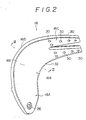
- Fig. 5 shows a tire slippage preventing device 10 according to a second embodiment of the present invention.
- the arm 16 in the second embodiment has one reinforcement member 32 buried in it in a way that the reinforement member 32 is indented near the bifurcation of the end portion 16C of the arm 16.
- three ribs 72 extended in the longitudinal direction of the arm 16 are formed along the width direction of the arm 16 on the intermediate portion 16B thereof and on the side of the tire contact surface E.
- bridge like ribs may be formed together with the arm 16 to both sides of the intermediate portion 16B of the amr 16 for providing additional reinforcement.
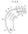
- Fig. 6 shows a tire slippage preventing device 10 according to a third embodiment of the present invention.
- one reinforement member 32 is buried in the arm 16, and an intermediate portion of the reinforcement member 32 is foled back at the end portion 16C close to the intermediate portion 16B and in front of the bifurcation of the arm 16.
- Fig. 7 shows a tire slippage preventing device 10 according to a fourth embodiment of the present invention.
- one reinforcement member 32 is folded back in it's intermediate portion down to the base portion 16A of the arm 16. Tehreby the arm 16 will be reinforced in the same way, as if four reinforcement members 32 would be buried in the longitudinal direction of the arm 16.
- Fig. 8 shows a tire slippage preventing device 10 according to a fifth embodiment of the present invention.
- one reinforcement member 32 is buried in the arm 16 crossing over itself.
- Fig. 9 shows a tire slippage preventing device 10 according to a sixth embodiment of the present invention.
- a plurality of reinforcement members 32 are buried in the arm 16 along the longitudinal direction thereof generally in parallel with each other. These reinforcement members 32 are interconnected at their intermediate portions to each other by other reinforcement members 32 extending in the width direction of the arm 16, thereby forming a frame-like disposition.
- Fig. 10 shows a tire slippage preventing device 10 according to a seventh embodiment of the present invention.
- the end portion 16C of the arm 16 is a type formed without a bifurcation.
- One reinforcing member 32 is buried an each side of the arm 16.
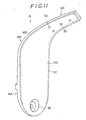
- Fig. 11 shows a tire slippage preventing device 10 according to an eighth embodiment of the present invention.
- end portion 16C of the arm 16 is a type formed without a bifurcation.
- One reinforcing member 32 is buried as to lie along the inside of both sides and the tip portion of the end portion 16C of the arm 16.
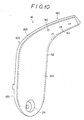
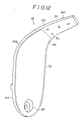
- Fig. 12 shows a tire slippage preventing device 10 according to a ninth embodiment of the present invention.
- the end portion 16C of the arm 16 is a type formed without a bifurcation.
- the reinforcement member 32 is a single one.
- the reinforcing member 32 is folded back at the end portion 16C closer to the intermediate portion 16B and in front of the projections 30 of the end portion 16C of the arm 16.
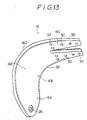
- Fig. 13 shows a tire slippage preventing device 10 according to a tenth embodiment of the present invention.
- the reinforcement member 32 buried in the arm 16 is not extended up to the tip portion of the end portion 16C of the arm 16, differing from the first embodiment. Structurally, the remaining parts of the tire slippage preventing device 10 are similar to those of the first embodiment.
- Fig. 14 shows a tire slippage preventing device 10 according to an eleventh embodiment of the present invention.
- the reinforcement member 32 buried in the arm 16 is not extended up to the tip portion of the end portion 16C of the arm 16, differing so from the seventh embodiment.
- the remaining parts of the tire slippage preventing device 10 are similar to those of the first embodiment.
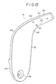
- Fig. 15 shows a tire slippage preventing device 10 according to a twelfth embodiment of the present invention.
- the reinforcement member 32 buried in the arm 16 is extended up to the vicinity of the tip portion of the end portion 16C of the arm 16, as compared with that of the ninth embodiment.
- the remaining parts of the tire slippage preventing device 10 are similar to those of the first embodiment.
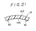
- Fig. 21 shows a tire slippage preventing device 10 according to a thirteenth embodiment of the present invention.
- the arm 16 is constructed such that the reinforcement members 32 are only partially buried in the arm 16. This has the advantage that the condition of the buried reinforcement member 32 can be confirmed from the outside of the arm 16. Further, burying of the reinforcement member 32 in the first to the twelfth embodiments can be changed to similar form as in the present embodiment.
Landscapes
- Engineering & Computer Science (AREA)
- Mechanical Engineering (AREA)
- Injection Moulding Of Plastics Or The Like (AREA)
- Tires In General (AREA)
Applications Claiming Priority (4)
| Application Number | Priority Date | Filing Date | Title |
|---|---|---|---|
| JP16303788 | 1988-06-30 | ||
| JP163037/88 | 1988-06-30 | ||
| JP297846/88 | 1988-11-25 | ||
| JP63297846A JP2719374B2 (ja) | 1988-06-30 | 1988-11-25 | タイヤ滑り止め装置及びその製造方法 |
Publications (1)
| Publication Number | Publication Date |
|---|---|
| EP0348926A2 true EP0348926A2 (de) | 1990-01-03 |
Family
ID=26488615
Family Applications (1)
| Application Number | Title | Priority Date | Filing Date |
|---|---|---|---|
| EP89111742A Withdrawn EP0348926A2 (de) | 1988-06-30 | 1989-06-28 | Vorrichtung zum Verhindern des Reifenschlupfes und deren Fertigungsverfahren |
Country Status (2)
| Country | Link |
|---|---|
| EP (1) | EP0348926A2 (de) |
| JP (1) | JP2719374B2 (de) |
Cited By (1)
| Publication number | Priority date | Publication date | Assignee | Title |
|---|---|---|---|---|
| CN102729733A (zh) * | 2011-04-01 | 2012-10-17 | 王树明 | 一种不充气车轮的万能缓冲装置 |
Family Cites Families (2)
| Publication number | Priority date | Publication date | Assignee | Title |
|---|---|---|---|---|
| JPS577373Y2 (de) * | 1976-08-11 | 1982-02-12 | ||
| JPS55104502U (de) * | 1979-01-18 | 1980-07-21 |
-
1988
- 1988-11-25 JP JP63297846A patent/JP2719374B2/ja not_active Expired - Lifetime
-
1989
- 1989-06-28 EP EP89111742A patent/EP0348926A2/de not_active Withdrawn
Cited By (1)
| Publication number | Priority date | Publication date | Assignee | Title |
|---|---|---|---|---|
| CN102729733A (zh) * | 2011-04-01 | 2012-10-17 | 王树明 | 一种不充气车轮的万能缓冲装置 |
Also Published As
| Publication number | Publication date |
|---|---|
| JPH0295906A (ja) | 1990-04-06 |
| JP2719374B2 (ja) | 1998-02-25 |
Similar Documents
| Publication | Publication Date | Title |
|---|---|---|
| AU2021200240B2 (en) | Reinforced rubber spoke for a tire | |
| JP3535909B2 (ja) | タイヤカーカス固定法 | |
| US20240100883A1 (en) | Non-pneumatic tire | |
| EP0928735A1 (de) | Innenumfangsseitige Antriebs- Gummigleiskette | |
| EP3727884B1 (de) | Verstärkter elastischer träger für einen luftlosen reifen | |
| KR20030085494A (ko) | 가요성 비공압 타이어 | |
| CN111565940A (zh) | 用于非充气轮胎的加强型弹性支撑件 | |
| US11745542B2 (en) | Curved reinforced resilient support for a non-pneumatic tire | |
| JPH078660B2 (ja) | 連結リンク式ゴムクローラ | |
| JP2005512865A (ja) | タイヤ用補強構造物のコードの取り付け方法 | |
| EP0348926A2 (de) | Vorrichtung zum Verhindern des Reifenschlupfes und deren Fertigungsverfahren | |
| US20020062897A1 (en) | Pneumatic tire having multiple element bead assembly | |
| EP1016554B1 (de) | Vollreifen | |
| US4446903A (en) | Non-pneumatic tire | |
| EP0006425A1 (de) | Reifen und Verfahren zu seiner Herstellung | |
| JPH04232101A (ja) | デュアルトレッドタイヤ | |
| JP4183030B2 (ja) | タイヤ/ホイール組立体 | |
| EP4081408B1 (de) | Speiche für nichtpneumatische reifen mit verbessertem elastomerischen gelenkelement | |
| JP4348106B2 (ja) | ゴムクローラの成形方法、及びゴムクローラ | |
| US7836930B2 (en) | Tire whereof at least one bead seat comprises a rib | |
| JPS62173306A (ja) | タイヤ滑り止め装置 | |
| JP5004131B2 (ja) | 道路用標示体 | |
| JP2721559B2 (ja) | タイヤ滑止具の巻付体及びその製造方法 | |
| EP0319338A2 (de) | Kette für Raupenfahrzeuge | |
| JPH0270513A (ja) | タイヤ滑り止め装置 |
Legal Events
| Date | Code | Title | Description |
|---|---|---|---|
| PUAI | Public reference made under article 153(3) epc to a published international application that has entered the european phase |
Free format text: ORIGINAL CODE: 0009012 |
|
| AK | Designated contracting states |
Kind code of ref document: A2 Designated state(s): CH DE FR LI |
|
| STAA | Information on the status of an ep patent application or granted ep patent |
Free format text: STATUS: THE APPLICATION IS DEEMED TO BE WITHDRAWN |
|
| 18D | Application deemed to be withdrawn |
Effective date: 19920102 |