EP0348870B1 - Constructions composed of several precast reinforced-concrete elements for use in the prestressed concrete construction method - Google Patents
Constructions composed of several precast reinforced-concrete elements for use in the prestressed concrete construction method Download PDFInfo
- Publication number
- EP0348870B1 EP0348870B1 EP89111620A EP89111620A EP0348870B1 EP 0348870 B1 EP0348870 B1 EP 0348870B1 EP 89111620 A EP89111620 A EP 89111620A EP 89111620 A EP89111620 A EP 89111620A EP 0348870 B1 EP0348870 B1 EP 0348870B1
- Authority
- EP
- European Patent Office
- Prior art keywords
- bridging
- structural member
- member according
- tube
- sleeve
- Prior art date
- Legal status (The legal status is an assumption and is not a legal conclusion. Google has not performed a legal analysis and makes no representation as to the accuracy of the status listed.)
- Expired - Lifetime
Links
Images


Classifications
-
- E—FIXED CONSTRUCTIONS
- E04—BUILDING
- E04C—STRUCTURAL ELEMENTS; BUILDING MATERIALS
- E04C5/00—Reinforcing elements, e.g. for concrete; Auxiliary elements therefor
- E04C5/08—Members specially adapted to be used in prestressed constructions
- E04C5/10—Ducts
-
- E—FIXED CONSTRUCTIONS
- E04—BUILDING
- E04H—BUILDINGS OR LIKE STRUCTURES FOR PARTICULAR PURPOSES; SWIMMING OR SPLASH BATHS OR POOLS; MASTS; FENCING; TENTS OR CANOPIES, IN GENERAL
- E04H7/00—Construction or assembling of bulk storage containers employing civil engineering techniques in situ or off the site
- E04H7/02—Containers for fluids or gases; Supports therefor
- E04H7/18—Containers for fluids or gases; Supports therefor mainly of concrete, e.g. reinforced concrete, or other stone-like material
- E04H7/20—Prestressed constructions
Abstract
Description
Die Erfindung bezieht sich auf einen aus mehreren Stahlbetonfertigteilen zusammengefügten und an deren Fugen mit erhärtender Füllmasse verbundenen Baukörper in einer Spannbetonbauweise. Ein solcher Baukörper ist z.B. aus der DE-B1-15 59 491 bekannt. Dieser vorbekannte Baukörper ist vornehmlich aus plattenförmigen Fertigteilen zusammengesetzt. Die Erfindung bezieht sich allgemein auf Baukörper gemäß dem Oberbegriff von Anspruch 1 und befaßt sich vornehmlich, aber nicht ausschließlich, mit solchen derartigen Baukörpern, deren Stahlbetonfertigteile sich zu einem zylindrischen Behälter ergänzen. Der Oberbegriff von Anspruch 1 ist auf die FR-A-25 96 439 bezogen, die später noch mehr im einzelnen erörtert wird.The invention relates to a structure composed of several prefabricated reinforced concrete parts and connected at the joints with hardening filling compound in a prestressed concrete construction. Such a structure is e.g. known from DE-B1-15 59 491. This previously known structure is primarily composed of plate-shaped prefabricated parts. The invention relates generally to structures according to the preamble of claim 1 and is primarily, but not exclusively, concerned with such structures, the reinforced concrete parts of which complement one another to form a cylindrical container. The preamble of claim 1 is related to FR-A-25 96 439, which will be discussed in more detail later.
Die Erfindung bezieht sich auf die Sonderform einer Spannbetonbauweise, bei der die Spannelemente erst nachträglich in bereits vorgefertigte Stahlbetonfertigteile eingebracht werden. Für deren Einbringung sind in den einzelnen Stahlbetonfertigteilen Hüllrohre einbetoniert, durch welche die Spannglieder eingezogen werden können und in denen sie sich für die Verspannung dehnen und verlagern können. Diese Spannbetonbauweise wird gewählt, wenn mehrere Stahlbetonfertigteile miteinander tragend verbunden werden sollen. Es ist dabei üblich, jedoch nicht in allen Fällen zwingend erforderlich und daher nach der Erfindung auch nur fakultativ vorgesehen, den Zwischenraum zwischen den Hüllrohren und den Spanngliedern nachträglich mit Injektionsmörtel mindestens teilweise aufzufüllen. Außerdem werden die Fugen zwischen aneinander anschließenden Stahlbetonfertigteilen mit erhärtender Füllmasse verbunden, üblicherweise einem Fugenmörtel.The invention relates to the special form of a prestressed concrete construction, in which the prestressing elements are only introduced subsequently into prefabricated reinforced concrete parts. For their insertion, cladding pipes are embedded in the individual prefabricated reinforced concrete parts, through which the tendons can be retracted and in which they can stretch and shift for tensioning. This prestressed concrete construction is chosen if several precast reinforced concrete parts are to be connected to each other in a load-bearing manner. It is common, but not absolutely necessary in all cases, and is therefore only optional, according to the invention, to subsequently at least partially fill the space between the cladding tubes and the tendons with injection mortar. In addition, the joints between each other subsequent prefabricated reinforced concrete parts connected with hardening filling compound, usually a grout.
Als Spannelemente dienen insbesondere sog. Spannlitzen oder Monolitzen, die aus einzelnen Drähten zusammengesetzt sind und im allgemeinen aus korrodierbarem hochfesten Spannstahl bestehen, der innerhalb einer Kunststoffummantelung mit Fettverfüllung angeordnet ist. Dadurch soll die Stahlkorrosion vermieden werden, z.B. unter dem Einfluß von Wasser oder gar aggressiven Flüssigkeiten, welche in dem Behälter aufbewahrt werden. Es wird sich zeigen, daß die Erfindung demgegenüber vorteilhaftere Bedingungen schafft, so daß auch andere Spannglieder Verwendung finden können, ggf. sogar solche mit korrodierbarer Oberfläche.In particular, so-called tensioning strands or monostrands are used as tensioning elements, which are composed of individual wires and generally consist of corrodible, high-strength tensioning steel which is arranged within a plastic sheathing with grease filling. This is to avoid steel corrosion, e.g. under the influence of water or even aggressive liquids which are kept in the container. It will be shown that the invention creates more advantageous conditions, so that other tendons can be used, possibly even those with a corrodible surface.
Die Erfindung bezieht sich insbesondere auf einen solchen Baukörper, der noch als Ganzes beweglich ist, weil die Füllmasse in den Fugen zwischen den Stahlbetonfertigteilen und ggf. der Injektionsmörtel noch nicht eingebracht sind. Es handelt sich dann um ein bewegliches zusammenhängendes Vorprodukt des fertigen Baukörpers.The invention relates in particular to such a structure, which is still movable as a whole, because the filling compound has not yet been introduced into the joints between the precast reinforced concrete parts and possibly the injection mortar. It is then a movable coherent preliminary product of the finished building.
Die Erfindung befaßt sich jedoch ebenso mit dem fertigen Baukörper, bei dem bereits die Füllmasse und ggf. der Injektionsmörtel erhärtet sind. Derartige fertige Baukörper können unbeweglich an Ort aus den vorgefertigten beweglichen Stahlbetonfertigteilen errichtet sein.However, the invention also deals with the finished structure, in which the filling compound and possibly the injection mortar have already hardened. Finished structures of this type can be immovably erected on site from the prefabricated movable reinforced concrete parts.
Bei derartigen Baukörpern erfolgt das Verspannen der Spannglieder im Regelfall erst nach Erhärten der Füllmasse in den Fugen zwischen den Stahlbetonfertigteilen. Das Einbringen des Injektionsmörtels kann je nach Art des verwendeten Spanngliedes vor oder nach dem Verspannen erfolgen.In such structures, the tendons are usually only tensioned after the filling compound has hardened in the joints between the precast reinforced concrete elements. Depending on the type of tendon used, the injection mortar can be introduced before or after tensioning.
Bei dem Baukörper nach der DE-B1-15 59 491 sind im Bereich der Fingen zwischen benachbarten Stahlbetonfertigteilen Überbrückungsrohre eingesetzt, die mit ihren beiden freien Enden in die Aussparungen der benachbarten Stahlbetonfertigteile eindringen und dort an zurückgesetzte Enden der Hüllrohre anschließen, wobei das jeweilige Überbrückungsrohr einen dem Innenquerschnitt der Hüllrohre entsprechenden Innenquerschnitt hat. Zur Abdichtung der jeweiligen Rohrverbindung zwischen Hüllrohr und Überbrückungsrohr ist dabei die über den Außenquerschnitt des Hüllrohres radial hinausragende Stirnfläche des Verbindungsrohres mittels eines plastischen Kitts mit dem Grund der jeweiligen Aussparung dicht verbunden.In the structure according to DE-B1-15 59 491, bridging pipes are used in the area of the fingers between neighboring prefabricated reinforced concrete parts, which penetrate with their two free ends into the recesses of the neighboring prefabricated reinforced concrete parts and connect there to recessed ends of the cladding pipes, the respective bridging pipe being one has the inside cross section corresponding to the inside cross section of the cladding tubes. For sealing the respective pipe connection between the cladding tube and the bridging tube, the end face of the connecting tube protruding radially beyond the outer cross section of the cladding tube is tightly connected to the base of the respective recess by means of a plastic cement.
Diese vorbekannte Rohrverbindungsart bedingt einen weitgehend starren Zusammenbau der Stahlbetonfertigteile des Baukörpers, welcher den auftretenden Toleranzen der Stahlbetonfertigteile nur höchst unvollkommen Rechnung trägt. Die toleranzausgleichenden Eigenschaften selbst eines plastischen Dichtkitts an einer Rohrstirnseite sind gering. Überbeanspruchungen der Plastizität führen zu Undichtigkeiten. Größere Toleranzen können praktisch höchstens lokal an einer bestimmten Stelle ausgeglichen werden. Damit werden die an sich sehr vorteilhaften sonstigen Eigenschaften des Baukörpers nach der DE-B1-15 59 491 nur sehr bedingt nutzbar.This previously known type of pipe connection requires a largely rigid assembly of the reinforced concrete precast elements of the structure, which only takes the imperfect tolerances of the reinforced concrete precast elements into account in an extremely imperfect manner. The tolerance-compensating properties of even a plastic sealing cement on one end of the pipe are low. Overstraining plasticity leads to leaks. Larger tolerances can practically only be compensated for locally at a certain point. The very advantageous other properties of the structure according to DE-B1-15 59 491 are therefore of very limited use.
Dementsprechend liegt der Erfindung die Aufgabe zugrunde, einen Baukörper zu schaffen, welcher wie der Baukörper nach der DE-B1-15 59 491 folgende Eigenschaften beibehält:
- a. freie und insbesondere unabhängige Wahl der Füllmasse in den Fugen zwischen benachbarten Stahlbetonfertigteilen einerseits und ggf. eines Injektionsmörtels andererseits;
- b. Vermeidung von Knickbeanspruchungen des Spanngliedes insbesondere in Fugenbereichen zwischen benachbarten Stahlbetonfertigteilen;
- c. die Möglichkeit einer im Normalfall vollständigen Verpressung der Hohlräume zwischen den Hüllrohren und den darin befindlichen Spanngliedern mit Injektionsmörtel unter praktisch vollständiger Hohlraumauffüllung und
- d. die Möglichkeit einer vielseitigen Verwendung von Spanngliedern;
und welcher darüber hinaus - e. bessere ausgleichende Eigenschaften bezüglich unterschiedlicher Toleranzen hat.
- a. free and in particular independent choice of the filling compound in the joints between neighboring prefabricated reinforced concrete parts on the one hand and possibly an injection mortar on the other hand;
- b. Avoidance of buckling stresses on the tendon, particularly in joint areas between adjacent prefabricated reinforced concrete parts;
- c. the possibility of a normally complete compression of the cavities between the cladding tubes and the tendons therein with injection mortar with practically complete cavity filling and
- d. the possibility of versatile use of tendons;
and what more - e. has better balancing properties with regard to different tolerances.
Die FR-A-25 96 439, von der der Oberbegriff von Anspruch 1 ausgeht, kommt der Erfindung im Vergleich mit der DE-B1-15 59 491 insoweit näher, als schon eine jeweils im Anschluß an die Fugengrenzfläche vorgesehene Aussparung konisch ausgebildet ist und im Inneren des Stahlbetonfertigteils in einen verjüngten Bereich übergeht, in den ein Hüllrohr des mit der Aussparung versehenen Stahlbetonfertigteils mündet und der ein in die Fuge eingesetztes Überbrückungsrohr des jeweiligen druckdichten Kanals 8 aufnimmt, der sich jeweils über das betreffende Hüllrohr zwischen benachbarten Stahlbetonfertigteilen fortsetzt. Nach der FR-A-25 96 439 sollen speziell die Hüllrohre zweier benachbarter Betonblöcke so genau fluchtend miteinander wie möglich angeordnet werden. Dabei sollen auftretende Größentoleranzen benachbarter Betonblöcke und ihrer Aussparungen ausgeglichen werden. Für diesen Zweck wird die Innenfläche des sich konisch erweiternden Bereichs der Aussparung als Dicht- und Abstützfläche für eine Dichthülse mit sich von innen nach außen konisch erweiterndem Querschnitt genutzt. Diese Dichthülse dient zur Zwangszentrierung der in den beiden benachbarten Betonblökken einbetonierten Hüllrohre relativ zueinander. Dabei ist das gummielastische Material der Dichthülse, welches sich verschieden weit komprimieren läßt, nebenher dazu bestimmt, Größentoleranzen der Abmessungen der beiden benachbarten Betonblöcke bzw. ihrer Aussparungen auszugleichen. Diese Zwangszentrierung in Verbindung mit sekundärem Toleranzausgleich erfolgt dadurch, daß erst die innerhalb der Hüllrohre angeordneten Spannlitzen verspannt und dann der Zwischenraum zwischen den Spannlitzen zur Fixierung der Verspannung mit dem Hüllrohr verspritzt werden. Bei dieser Verspannung werden die beiden benachbarten Betonblöcke unter Verkleinerung ihrer Fuge näher aneinander herangezogen. Die sich verjüngenden Bereiche der beiden Aussparungen sind dabei lediglich als Verschiebungsbereiche genutzt, um bei konstanter axialer Länge des jeweiligen überbrückenden Rohrteils die beiden Betonblöcke näher aneinander heranziehen zu können. Es ist somit eine axiale Verspannung erforderlich, um die Dichtheit zu erreichen. Diese axiale Verspannung führt sogar zu dem Risiko des Einklemmens der jeweiligen elastischen Dichthülse im zentralen Teil, einem Risiko, dem nur bedingt mittels einer zusätzlich vorgesehenen Umfangsnut entgegengewirkt werden kann. Ein axialer Versatz der Betonblöcke gegeneinander ist darüber hinaus nur bedingt möglich, da im Vordergrund die Zwangszentrierung der Betonteile gegeneinander beim Verspannen unter Kompression der jeweiligen Dichthülse steht. Eine Abwinklung der Betonteile gegeneinander ist weder gewollt noch ernsthaft praktisch möglich.FR-A-25 96 439, from which the preamble of claim 1 starts, compares the invention to that of the invention DE-B1-15 59 491 as far as a recess provided in connection with the joint interface is conical and merges into a tapered area in the interior of the precast reinforced concrete part, into which a cladding tube of the precast reinforced concrete part opens and the one into the joint inserted bridging pipe of the respective pressure-
Diese der Erfindung zugrunde liegende Aufgabe wird bei einem gattungsgemäßen Baukörper durch die kennzeichnenden Merkmale von Anspruch 1 gelöst.This object on which the invention is based is achieved in a generic structure by the characterizing features of claim 1.
Gemäß den Forderungen a. bis d. bleiben bei dem erfindungsgemäßen Baukörper die Fugen zwischen den einzelnen Stahlbetonbauteilen einerseits und die Räume um die Spannglieder andererseits selbst im Fugenbereich voneinander separiert, so daß eine vollständig freie Wahl für die Füllmassen der Fugen und ggf. den Injektionsmörtel besteht. Es kann dabei nicht zu einer schädlichen Wechselwirkung der erhärteten Füllmasse der Fuge und den Spanngliedern kommen. Die druckdichte Ausführung der zwischen den einzelnen Spannbetonfertigteilen durchgehenden Umhüllung der Spannglieder stellt ferner weiter sicher, daß in diese Injektionsmörtel unter einem verhältnismäßig hohen Druck injiziert werden und so eine Entstehung von Hohlräumen um die Spannglieder herum praktisch zuverlässig vermieden werden kann. Dadurch können weiter auch Spannglieder mit korrodierbarer Oberfläche durch geeignete Wahl der Injektionsmörtel problemlos einsetzbar werden.According to the requirements a. to d. In the structure according to the invention, the joints between the individual reinforced concrete components on the one hand and the spaces around the tendons on the other hand, even in the joint area, are separated from one another, so that there is a completely free choice for the fillings of the joints and possibly the injection mortar. There can be no harmful interaction between the hardened filling compound of the joint and the tendons. The pressure-tight design of the continuous encapsulation of the tendons between the individual prestressed concrete parts also ensures that injection mortars are injected at a relatively high pressure and thus the formation of voids around the tendons can be avoided practically reliably. As a result, tendons with a corrodible surface can also be used without any problems by suitable choice of injection mortar.
Der Forderung e. trägt die Ausbildung der Rohrverbindungen an beiden Enden des jeweiligen Überbrückungsrohres als gummielastische Gelenke Rechnung.The claim e. takes into account the formation of the pipe connections at both ends of the respective bridging pipe as rubber-elastic joints.
Als gummielastische Gelenke können Dichtelemente dienen, die zweckmäßig aus elastisch-nachgiebigem Material bestehen, z.B. aus Gummi oder einem Gummiersatzstoff. Diese Dichtelemente können dabei ggf. sogar auf einem Rohr der Rohrverbindung fest angebracht, z.B. aufvulkanisiert oder aufgeklebt sein. Meist reicht jedoch eine formschlüssige oder gar nur reibschlüssige Anordnung.Sealing elements which are expediently made of resilient material, for example of rubber or a rubber substitute, can serve as rubber-elastic joints. These sealing elements can possibly even be firmly attached to a pipe of the pipe connection, for example vulcanized or glued on. Usually, however, a form-fitting or even a frictional arrangement is sufficient.
Bei der Abdichtung ist grundsätzlich zu beachten, daß der Stahlbeton der einzelnen Stahlbetonfertigteile selbst für unter höherem Injektionsdruck eingebrachten Injektionsmörtel hinreichend druckdicht ist. Das Dichtelement muß daher in erster Linie eine Abdichtung gegenüber den Fugenbereichen zwischen benachbarten Stahlbetonfertigteilen sicherstellen. Es reicht daher in vielen Fällen aus, wenn das Dichtelement nur umfangsseitig an dem betreffenden kanalbildenden Rohr angeordnet ist und Injektionsmörtel an den Anschlußstellen zwischen benachbarten kanalbildenden Rohren innerhalb der Stahlbetonfertigteile etwas bis in Anlage am Stahlbeton des betreffenden Fertigteils herausquillt.When sealing, it should always be noted that the reinforced concrete of the individual prefabricated reinforced concrete parts is sufficiently pressure-tight, even for injection mortar introduced under higher injection pressure. The sealing element must therefore primarily ensure a seal with respect to the joint areas between adjacent prefabricated reinforced concrete parts. It is therefore sufficient in many cases if the sealing element is arranged only on the circumferential side of the channel-forming pipe in question and injection mortar at the connection points between adjacent channel-forming pipes within the precast reinforced concrete parts slightly oozes out into contact with the reinforced concrete of the precast element concerned.
Im Rahmen der Erfindung lassen sich die gummielastischen Eigenschaften eines aus entsprechendem Material gefertigten Dichtelements zusätzlich für eine Gelenkfunktion dann nutzbar machen, wenn benachbarte Stahlbetonfertigteile im Baukörper mit etwas seitlichem Versatz im Fugenbereich relativ zueinander angeordnet werden. Das Überbrückungsrohr, bei dem ein Dichtelement an beiden Enden als gummielastisches Gelenk vorgesehen wird, ermöglicht sogar eine besonders große seitliche Beweglichkeit nach Art eines Doppelgelenkes. Das Dichtelement dient aufgrund seiner Formelastizität zusätzlich auch noch als Mittel zum Halten des in das betreffende Stahlbetonfertigteil eingesteckten Überbrückungsrohres. Es ist grundsätzlich möglich, daß die Dichtelemente gegenüber den freien Enden der kanalbildenden Rohre auch axial deutlich versetzt sind.Within the scope of the invention, the rubber-elastic properties of a sealing element made of a corresponding material can additionally be used for a joint function if adjacent reinforced concrete prefabricated parts are arranged relative to one another in the structure with a slight lateral offset in the joint area. The bridging tube, in which a sealing element is provided at both ends as a rubber-elastic joint, even enables particularly great lateral mobility in the manner of a double joint. Due to its elasticity in form, the sealing element also serves as a means of holding the bridging tube inserted into the prefabricated reinforced concrete part in question. It is fundamentally possible that the sealing elements are also axially clearly offset from the free ends of the channel-forming tubes.
Da die in den einzelnen Stahlbetonfertigteilen einbetonierten Hüllrohre durch in den Fugenbereichen zwischen den Stahlbetonfertigteilen angeordnete zusätzliche Überbrückungsrohre kommunizierend aneinander angeschlossen werden, lassen sich in den Fugenbereichen überstehende Enden der Hüllrohre vermeiden, welche transport- und aufstellungstechnisch ungünstig erscheinen. Die Überbrückungsrohre können beispielsweise erst unmittelbar vor der Montage des erfindungsgemäßen Baukörpers aus den einzelnen Stahlbetonfertigteilen in jeweils eine Fugengrenzfläche derselben eingesetzt werden. Wie bei der DE-B1-15 59 491 wird dabei insbesondere sichergestellt, daß sich beim Einziehen der Spannglieder in die durchgehenden druckdichten Kanäle durch die Verwendung der Überbrückungsrohre keine oder höchstens geringfügige mechanische Hemmungen ergeben. Bei dieser Bauweise ergibt sich vielmehr ein doppelgelenkiger und elastischnachgiebiger Toleranzausgleich.Since the cladding pipes concreted in the individual reinforced concrete parts are communicatively connected to one another by additional bridging pipes arranged in the joint areas between the reinforced concrete parts, protruding ends of the cladding pipes can be avoided in the joint areas, which appear to be unfavorable in terms of transport and installation technology. The bridging pipes can, for example, only be inserted into the joint boundary surface of the individual prefabricated reinforced concrete parts immediately before the assembly of the structure according to the invention will. As with DE-B1-15 59 491, it is ensured in particular that when the tendons are pulled into the continuous pressure-tight channels, no or at least slight mechanical inhibitions result from the use of the bridging tubes. Rather, this type of construction results in a double-jointed and resilient tolerance compensation.
Ein Hauptmerkmal der Erfindung besteht demzufolge darin, ein gummielastisches Gelenk jeweils zwischen einem im Stahlbetonfertigteil fest einbetonierten Hüllrohr und einem diesem gegenüber abwinkelbaren, die Fuge überbrückenden Überbrückungsrohr zu schaffen, indem eine für die Funktion des gummielastischen Elements geeignet ausgebildete elastische Dichtung innerhalb des verjüngten Bereichs zwischen der Außenmantelfläche des die Fuge überbrückenden Rohrteils einerseits und der Innenmantelfläche des verjüngten Bereichs andererseits angeordnet wird, wobei in Übereinstimmung mit der FR-A-25 96 439 das in dem Stahlbetonfertigteil fest einbetonierte Hüllrohr in den verjüngten Bereich einmündet.A main feature of the invention is therefore to create a rubber-elastic joint between a cladding tube firmly concreted in the precast reinforced concrete part and a bridging tube that can be angled relative to it and bridges the joint, by providing an elastic seal that is suitable for the function of the rubber-elastic element within the tapered area between the The outer circumferential surface of the pipe part bridging the joint on the one hand and the inner circumferential surface of the tapered region on the other hand is arranged, in accordance with FR-A-25 96 439 the cladding tube firmly concreted in the reinforced concrete precast part opens into the tapered region.
Bei der Anordnung nach der Erfindung wird bewußt in Kauf genommen oder sogar für bestimmte Konstruktionen bewußt angestrebt, daß die Hüllrohre benachbarter Betonfertigteile im endgültigen Montagezustand außer Fluchtung sind. Die dabei erforderliche Schrägstellung des die Fuge überbrückenden Rohrteils wird dabei durch den offenen Winkel des konischen Einführtrichters der Aussparung ermöglicht, welcher von einer gummielastischen Abdichtung freibleibt und lediglich die Zusatzfunktion hat, als Einführhilfe für das die Fuge überbrükkende Rohrteil bei der Montage zu dienen.In the arrangement according to the invention, it is consciously accepted or even consciously sought for certain constructions that the cladding tubes of adjacent prefabricated concrete parts are out of alignment in the final assembly state. The required oblique position of the pipe part bridging the joint is made possible by the open angle of the conical insertion funnel of the recess, which remains free of a rubber-elastic seal and only has the additional function of serving as an insertion aid for the pipe part bridging the joint during assembly.
Die Abdichtung der Rohrverbindung wird innerhalb des verjüngten Bereichs vorgenommen und für die beliebige Einstellung der gewünschten Abwinklung als am Grunde des Einführtrichters angeordnetes gummielastisches Gelenk gestaltet.The pipe connection is sealed within the tapered area and designed for the arbitrary adjustment of the desired angle as a rubber-elastic joint arranged at the base of the insertion funnel.
Im Rahmen der Erfindung ist es dabei ohne weiteres möglich, daß zunächst der Zwischenraum zwischen den Spannlitzen und den Hüllrohren verspritzt und dann erst die Spannlitzen verspannt werden, da diese Verspannung nicht mehr eine Zwangszentrierungsfunktion wie im Falle der FR-A-25 96 439 hat. Die Erfindung ermöglicht vielmehr eine freie axiale Einstellung in den verjüngten Bereichen.In the context of the invention, it is readily possible that the space between the tensioning strands and the cladding tubes is first sprayed and only then the tensioning strands are tensioned, since this tensioning is no longer a Forced centering function as in the case of FR-A-25 96 439. Rather, the invention enables free axial adjustment in the tapered areas.
Eine Abwinklung der Betonteile gegeneinander ist bei entsprechender Gestaltung und Anordnung der gummielastischen Dichtung sogar bis in den Bereich einer Abwinklung des trichterförmigen Öffnungswinkels der Ausnehmung möglich und für bestimmte Konstruktionsaufgaben bewußt angestrebt.Angling the concrete parts against each other is possible with a corresponding design and arrangement of the rubber-elastic seal even up to the area of angling the funnel-shaped opening angle of the recess and is consciously aimed for certain construction tasks.
Anspruch 2 sieht eine Möglichkeit vor, bei der eine Überbrückung der Fugen zwischen benachbarten Stahlbetonfertigteilen durch ein teleskopisch verschiebbares Glied vorgesehen ist, welches im Transportzustand in das betreffende Stahlbetonfertigteil ganz oder im wesentlichen eingeschoben sein kann. Das hat nicht nur Bedeutung bezüglich der Transportmöglichkeit, sondern auch dann, wenn ein ringförmig geschlossener Baukörper mit dem letzten Stahlbetonfertigteil ergänzt werden muß. Während man bei noch unvollständiger ringförmiger Aufstellung die einzelnen Elemente des Ringes in Umfangsrichtung ineinander stecken kann, bestehen Schwierigkeiten beim radialen Einfügen des letzten Stahlbetonfertigteils in den dann geschlossenen Ring, beispielsweise die Wand eines zylindrischen Behälters (vgl. auch Anspruch 13). Entsprechendes gilt auch in anderen Fällen, wenn ein Stahlbetonfertigteil nachträglich in eine Lücke eingefügt werden muß, beispielsweise ein Fertigteil in einer Sonderausführung, z.B. wenn alleine ein Einsetzen von oben oder unten her möglich ist. Anspruch 4 betrifft dabei den bevorzugten Fall einer Betätigung des teleskopischen Gliedes mittels eines Druckmediums. Neben pneumatischen und hydraulischen Betätigungen ist dabei vorzugsweise an eine Betätigung durch hinreichend fließfähigen druckübertragenden Zementmörtel gedacht, der nach seinem Erstarren zugleich eine Feststellung des teleskopischen Gliedes in der ausgefahrenen Position sicherstellt. In anderen Fällen müßte man zusätzliche Sicherungsmaßnahmen ergreifen, z.B. Endstellungssicherungen. Ein derartiger Zementmörtel würde dabei auch einen Kanal im Stahlbetonfertigteil, durch welchen das Druckmedium aufgebracht wird, verschließen.
Die erwähnte Ausführungsform mit teleskopischem Glied kann generell vorgesehen sein; meist reicht es jedoch, diese Ausführungsform nur als Sonderform neben den anderen beschriebenen Ausführungsformen einzusetzen.The aforementioned embodiment with a telescopic link can generally be provided; however, it is usually sufficient to use this embodiment only as a special form in addition to the other described embodiments.
Auch bei diesen teleskopischen Rohrverbindungen stellt das jeweils verwendete Dichtelement ein gummielastisches Gelenk dar, das bei Rohrbiegung in Anspruch genommen wird. Eine solche Rohrbiegung stellt bei den hier in Betracht gezogenen Dimensionierungen und Bemessungen keinen unverhältnismäßigen Widerstand für den angestrebten Toleranzausgleich dar.With these telescopic pipe connections, the sealing element used in each case represents a rubber-elastic joint that is used when the pipe is bent. Such a pipe bend does not represent a disproportionate resistance to the desired tolerance compensation in the dimensions and dimensions considered here.
Es ist zweckmäßig, einen Kolben, über den das Druckmittel auf das teleskopische Glied, d.h. die Überbrückungsmuffe, einwirkt, auch außen gleitend zu führen und so Nebenströme des Druckmittels, welche für die Betätigung nicht benötigt werden, praktisch auszuschließen. Die Ansprüche 6 und 7 bieten hierfür zwei konstruktive Möglichkeiten, die gesondert, aber auch gemeinsam realisiert sein können.It is expedient to have a piston through which the pressure medium acts on the telescopic member, i.e. the bridging sleeve acts to also slide on the outside and practically exclude secondary flows of the pressure medium that are not required for actuation.
Gemäß Anspruch 8 kann das als gummielastisches Gelenk ausgebildete Dichtelement in Doppelfunktion auch als der Kolben eines auf oder in dem Hüllrohr teleskopisch verschiebbaren Gliedes, der Überbrückungsmuffe, dienen, wobei dann nach Anspruch 9 vorzugsweise das als Kolben dienende Dichtelement auch gegenüber einer vorgesehenen Gleitführung dichtet.According to
Bisher wurden nur Bauformen ausdrücklich angesprochen, bei denen das als gummielastisches Gelenk vorgesehene Dichtelement außen am Beton des Stahlbetonfertigteils abgestützt ist (vgl. Anspruch 8). Alternativ kann man jedoch nach Anspruch 12 das Dichtelement außen auch an einer Auftulpung des Hüllrohres abstützen, wobei ggf. diese Auftulpung wiederum ihrerseits am Beton des Stahlbetonfertigteils abgestützt sein kann, aber nicht muß.So far, only designs were expressly addressed in which the sealing element provided as a rubber-elastic joint is supported on the outside of the concrete of the precast reinforced concrete element (cf. claim 8). As an alternative, however, the sealing element can also be supported on the outside on a bulge of the cladding tube, this bulge in turn, if necessary, in turn being supported on the concrete of the precast reinforced concrete part, but need not be.
Der erfindungsgemäße Baukörper ist, wie schon erwähnt, insbesondere auch für die Herstellung eines zylindrischen Behälters geeignet, bei dem sich die Stahlbetonfertigteile zum Behältermantel ergänzen (Anspruch 13). Es sind dabei insbesondere großformatige Baukörper angesprochen, wobei im Falle des Beispiels eines zylindrischen Behälters Durchmesser von sechs bis dreißig Metern und mehr sowie Höhen von drei bis acht Metern und mehr typisch sind.As already mentioned, the structure according to the invention is also particularly suitable for the production of a cylindrical container in which the reinforced concrete precast elements are located complement to the container jacket (claim 13). In particular, large-format structures are addressed, with diameters of six to thirty meters and more and heights of three to eight meters and more being typical in the case of a cylindrical container.
Bisher wurden die als gummielastische Gelenke dienenden Dichtelemente, soweit konkret beschrieben, als Kompressionsdichtungen dargestellt. Gemäß Anspruch 14 findet stattdessen eine Lippendichtung in einer bestimmten Anordnung Anwendung. Deren Dichtwirkung wird erst durch zwischen die Lippen geratendes Kompressionsmittel erzeugt. Das Kompressionsmittel kann der Injektionsmörtel beim Verspritzen der in den einzelnen Stahlbetonfertigteilen einbetonierten Hüllrohre sein, der auch an einer Fuge zwischen den Hüllrohren und den dazwischengesetzten Überbrückungsrohren (oder Überbrückungsmuffen im Sinne von Anspruch 2) zwischen die Dichtlippen geraten kann. Dieser Effekt wird noch verstärkt, wenn im Sinne von Anspruch 4 eine teleskopisch verschiebbare Überbrückungsmuffe dadurch hydraulisch in ihre ausgeschobene Betriebsstellung verschoben wird, indem als Druckfluid ein von außen durch einen eigenen Kanal im Stahlbetonfertigteil zugeführter Injektionsmörtel verwendet wird, der anschließend zu einer Verspritzungsmasse erhärtet.So far, the sealing elements serving as rubber-elastic joints, as far as specifically described, have been represented as compression seals. According to
Es ist möglich, den Schaft der Lippendichtung generell ebenso wie die früher angesprochene Kompressionsdichtung mit radialer Vorspannung an ihrer jeweiligen Dichtfläche anliegen zu lassen. Dies ist jedoch bei Verwendung einer Lippendichtung nicht zwingend erforderlich, ja oft gar nicht einmal erwünscht, um die Montage zu erleichtern.It is possible, in general, to have the lip of the lip seal, like the compression seal mentioned earlier, rest against its respective sealing surface with radial prestress. However, this is not absolutely necessary when using a lip seal, and is often not even desirable in order to facilitate assembly.
Ein Sonderfall liegt vor bei Verwendung einer Überbrückungsmuffe im Sinne von Anspruch 2. In diesem Fall besteht das Problem, daß auch in die Hüllrohre eingespritzter Injektionsmörtel zwischen der Stirnseite des Hüllrohres innerhalb der Überbrückungsmuffe und dem der Fuge abgewandten Ende derselben unter der an der Überbrückungsmuffe anliegenden Lippe der Lippendichtung nach außen rückwärts in Richtung zur Fuge kriechen kann; die Fuge soll jedoch gerade im Rahmen der Erfindung von in die Hüllrohre eingespritztem Injektionsmörtel freigehalten werden. Dem kann man vorbeugen in der Weise, daß gemäß Anspruch 15 der Schaft der Lippendichtung auf die Überbrückungsmuffe radial vorgespannt wird, wie dies bei einer Kompressionsdichtung an sich von vornherein der Fall ist.A special case exists when using a bridging sleeve in the sense of
Zum Herstellen der Vorspannung dient vorzugsweise ein auf den Schaft der Lippendichtung außen aufgeschobener Stützring (Anspruch 16).A support ring pushed onto the shaft of the lip seal on the outside preferably serves to produce the prestress (claim 16).
Die Lippen der Lippendichtung brauchen nicht unmittelbar an einem den durchgehenden druckdichten Kanal bildenden Rohr oder an dem Beton des Stahlbetonfertigteils anzuliegen, sondern es reicht auch aus, wenn die Abdichtung gegenüber einem mit den genannten Teilen dicht verbundenen Zwischenteil erfolgt. Insbesondere wird hierzu nach Anspruch 17 der eine Gleitführung für die Überbrückungsmuffe bildende Führungsteil im Sinne von Anspruch 7 in Betracht gezogen.The lips of the lip seal do not need to rest directly on a pipe forming the continuous pressure-tight channel or on the concrete of the precast reinforced concrete part, but it is also sufficient if the seal is made against an intermediate part which is tightly connected to the parts mentioned. In particular, according to claim 17, the guide part forming a sliding guide for the bridging sleeve is considered within the meaning of claim 7.
Nach einem weiteren Aspekt können gemäß Anspruch 18 die Überbrückungsrohre als Abstandhalter zwischen benachbarten Stahlbetonfertigteilen vorgesehen werden und dabei indirekt deren Fugen im Rahmen der praktisch auftretenden Toleranzen bilden. Toleranzen können dabei sowohl bei der Abstützung der Überbrückungsrohre an den Stahlbetonfertigteilen als auch bezüglich des Abstandes der Abstützstellen zu den fugenbildenden Flächen des jeweiligen Stahlbetonfertigteils auftreten. Eine Äquidistanzierung der Fugen ist daher im Rahmen dieser Weiterbildungsidee zwar an sich möglich, jedoch kann die Einstellung der Weite der Fugen auch die erwähnten Toleranzen bewußt in Kauf nehmen.According to a further aspect, the bridging pipes can be provided as spacers between adjacent prefabricated reinforced concrete parts and indirectly form their joints within the tolerances that occur in practice. Tolerances can occur both when the bridging pipes are supported on the precast reinforced concrete elements and with regard to the distance between the supporting points and the joint-forming surfaces of the respective precast reinforced concrete element. An equidistance of the joints is therefore possible as part of this further training idea, but the adjustment of the width of the joints can also consciously accept the tolerances mentioned.
Vorzugsweise ist gemäß Anspruch 19 ein als gummielastisches Gelenk vorgesehenes Dichtelement axial an einem Vorsprung eines einen durchgehenden druckdichten Kanal bildenden Rohres abgestützt. Dies hat besondere Bedeutung in Verbindung mit einer Überbrückungsmuffe gemäß Anspruch 2, die axial teleskopisch verschoben wird, kann aber ggf. auch bei den Überbrückungsrohren allgemein von Bedeutung sein.Preferably, a sealing element provided as a rubber-elastic joint is axially supported on a projection of a tube forming a continuous pressure-tight channel. This is of particular importance in connection with a bridging sleeve according to
Anspruch 20 sieht vor, in einem solchen Fall den Vorsprung als Sicke auszubilden. Damit kann man einerseits Material einsparen, indem beispielsweise das betreffende Rohr mit im wesentlichen gleichbleibender Rohrstärke gefertigt wird. Außerdem ist eine relativ einfache Herstellung durch Aufblasen des betreffenden Rohres gegen eine Außenform mittels eines eingebrachten aufblasfähigen Druckkörpers, beispielsweise in Gestalt eines Kunststoffschlauches, möglich.
Sei es, daß der Vorsprung in diesem Sinne als Sicke ausgebildet ist, sei es, daß er konventionell ausgebildet ist, in beiden Fällen sieht Anspruch 21 für den Vorsprung noch eine Zweitfunktion für den Fall vor, daß der Vorsprung an einer Überbrückungsmuffe gemäß Anspruch 2 ausgebildet ist. Dann kann der Vorsprung insbesondere im Falle des Anspruchs 5, ggf. aber auch ohne dessen Merkmal, als Gleitführungselement bei der teleskopischen Verschiebung der Überbrückungsmuffe dienen.Be it that the projection in this sense is formed as a bead, or that it is conventional, in both cases claim 21 provides a second function for the projection in the event that the projection is formed on a bridging sleeve according to
Insbesondere für eine solche Überbrückungsmuffe sieht dann Anspruch 22 noch einen weiteren mittleren Vorsprung vor, der im geschilderten Sinne ebenfalls als Sicke ausgebildet sein kann, jedoch nicht sein muß, und der als zusätzliche intermediäre Führung der Überbrückungsmuffe während deren teleskopischer Ausschiebung vor Erreichen eines radial haltenden Eingriffs im gegenüberliegenden Stahlbetonfertigteil nutzbar gemacht wird.In particular for such a bridging sleeve, claim 22 then provides a further central projection, which in the sense described can also be formed as a bead, but does not have to be, and which as an additional intermediate guide of the bridging sleeve during its telescopic extension before reaching a radially holding engagement in the opposite precast reinforced concrete part.
Noch ein Aspekt ist in Anspruch 23 angesprochen für den Fall, daß zur Herstellung des Baukörpers teils allgemein Überbrückungsrohre und teils spezielle Überbrückungsmuffen gemäß Anspruch 2 Verwendung finden, beispielsweise bei Herstellung der Wandung eins rings geschlossenen runden Behälters Überbrückungsrohre im Normalfall, aber Überbrückungsmuffen beim Einsetzen des letzten, die Wand schließenden Stahlbetonfertigteils.Another aspect is addressed in claim 23 in the case that for the manufacture of the structure partly general bridging pipes and partly special bridging sleeves are used according to
Anspruch 24 sieht für diesen Fall vor, die Überbrückungsrohre bzw. die Überbrückungsmuffen aus gleichen vorgefertigten Baukörpern herzustellen, um den Teilebedarf zu reduzieren. Dabei kann man für die Überbrückungsrohre auch die mittleren Vorsprünge gemäß Anspruch 22 mit verwenden, obwohl sie keine Funktion mehr erfüllen, aber auch nicht hinderlich sind. Andererseits hat sich insbesondere die Möglichkeit ergeben, Überbrückungsmuffen einfach durch stirnseitiges Beschneiden von Überbrückungsrohren zu gewinnen.In this case, claim 24 provides for the bridging pipes or the bridging sleeves to be produced from the same prefabricated structures in order to reduce the parts requirement. You can also use the middle projections according to claim 22 for the bridging tubes, although they no longer perform a function, but are also not a hindrance. On the other hand, there has been the possibility, in particular, of obtaining bridging sleeves simply by cutting bridging pipes at the end.
Die einzelnen Aspekte der Ansprüche 14 bis 24 können im Rahmen der Erfindung einzeln und auch in Kombination oder Unterkombination verwirklicht sein.The individual aspects of
Vorzugsweise sind die gummielastischen Gelenke, die von den Dichtelementen gebildet sind, auf einem Rohr der jeweiligen Rohrverbindung vormontiert (Anspruch 25). Im Falle der Verwendung von Überbrückungsrohren nach Anspruch 2 erfolgt dabei zweckmäßig die Vormontierung nur auf dem jeweiligen Überbrückungsrohr (Anspruch 26), wodurch der Vorteil der Doppelgelenkwirkung noch mit einer Montageerleichterung verbunden wird.The rubber-elastic joints, which are formed by the sealing elements, are preferably preassembled on a pipe of the respective pipe connection (claim 25). In the case of using bridging pipes according to
Die Erfindung wird im folgenden anhand schematischer Zeichnungen an mehreren Ausführungsbeispielen noch mehr im einzelnen erläutert. Es zeigen:
- Fig. 1 ausschnittweise einen Schnitt durch zwei benachbarte Betonfertigteile im Fugenbereich, die zu einem Baukörper gemäß der Erfindung vereinigt werden, und zwar mit Darstellung von zwei Varianten in den beiden verschiedenen Stahlbetonfertigteilen zugeordneten Teilbildern;
- Fig. 2 und 3 Darstellungen einer weiteren Ausführungsform mit einem teleskopischen Glied, wobei Fig. 2 in sonst gleichbleibender Darstellungsweise nur ein einziges Stahlbetonfertigteil mit eingeschobenem teleskopischen Glied und Fig. 3 in der Darstellungsweise der Fig. 1 die Verbindung von zwei Stahlbetonfertigteilen mit ausgeschobenem teleskopischen Glied zeigt;
- Fig. 4 ausschnittweise einen Schnitt durch zwei benachbarte Betonfertigteile im Fugenbereich, die zu einem Baukörper gemäß der Erfindung vereinigt werden, wobei zur Verbindung der Hüllrohre Überbrückungsrohre mit Lippendichtungen vorgesehen sind;
- Fig. 5a und 5b in gleichartiger Darstellung wie in Fig. 1 eine Alternative, bei der als Überbrückungsrohre auf Hüllrohren teleskopisch verschiebbare Überbrückungsmuffen mit Lippendichtungselementen Anwendung finden, die in Fig. 5a im ausgeschobenen Einbauzustand und in Fig. 5b in einer Zwischenstellung beim Ausschieben dargestellt sind; und
- Fig. 6 in vergrößerter Teilansicht von Fig. 5a und Fig. 5b eine Modifikation im Bereich der Anordnung der als Dichtelement wie bei den Ausführungsformen nach Fig. 4 und 5 Anwendung findenden Lippendichtung.
- 1 shows a section of a section through two adjacent prefabricated concrete parts in the joint area, which are combined to form a building structure according to the invention, namely with the representation of two variants in the two different prefabricated reinforced concrete parts;
- 2 and 3 representations of a further embodiment with a telescopic link, FIG. 2 in an otherwise constant manner of representation only a single reinforced concrete element with inserted telescopic element and FIG. 3 in the representation of FIG. 1 the connection of two reinforced concrete elements with extended telescopic element shows;
- 4 shows a section of a section through two adjacent prefabricated concrete parts in the joint area which are combined to form a structure according to the invention, bridging pipes with lip seals being provided for connecting the cladding pipes;
- 5a and 5b in an illustration similar to that in FIG. 1, an alternative in which the bypass tubes are Cladding tubes, telescopically displaceable bridging sleeves with lip sealing elements are used, which are shown in FIG. 5a in the extended installation state and in FIG. 5b in an intermediate position when extended; and
- 6 shows an enlarged partial view of FIGS. 5a and 5b, a modification in the area of the arrangement of the lip seal used as a sealing element as in the embodiments according to FIGS. 4 and 5.
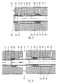
Den verschiedenen Ausführungsformen der Fig. 1 bis 3 ist folgendes gemeinsam:
Im Beton von Stahlbetonfertigteilen 2 sind zylindrische Hüllrohre 4, vorzugsweise aus Kunststoff oder aber einem anderen Material, einbetoniert.The various embodiments of FIGS. 1 to 3 have the following in common:
Mehrere Stahlbetonfertigteile werden über eine Fuge 6 zu einem Baukörper zusammengefügt, wobei die Fugen 6 beim fertigen Baukörper mit nicht dargestellter erhärteter Füllmasse verbunden sind.Several prefabricated reinforced concrete parts are joined via a joint 6 to form a building structure, the
Die Hüllrohre 4 der einzelnen Stahlbetonfertigteile sind im Baukörper im Idealfall axial fluchtend miteinander angeordnet. In praxi kann es bei allen Ausführungsformen beim Zusammenfügen der Stahlbetonfertigteile zu dem Baukörper zu einer gewissen seitlichen Versetzung zueinander kommen. Aber auch dann sollen die Hüllrohre 4 benachbarter Stahlbetonfertigteile 2 immer noch annähernd so fluchtend angeordnet sein, daß in die Hüllrohre 4 benachbarter Stahlbetonfertigteile ein nicht dargestelltes gemeinsames Spannglied eingezogen werden kann. Diese Spannglieder haben dabei einen Außendurchmesser, der deutlich kleiner als der Innendurchmesser der Hüllrohre 4 ist. Der dabei verbleibende Zwischenraum wird möglichst vollständig mit ebenfalls nicht dargestelltem Injektionsmörtel verfüllt.The
Ebenfalls nicht dargestellt sind die erforderlichen Mittel, um die Spannglieder im zusammengefügten Baukörper zur Herstellung einer Spannbetonbauweise zu verspannen.Also not shown are the means required to brace the tendons in the assembled structure for producing a prestressed concrete construction.
Die verschiedenen Ausführungsformen der Fig. 1 bis 3 geben unterschiedliche Mittel wieder, mit denen die Hüllrohre 4 über den Bereich der Fugen 6 zwischen benachbarten Stahlbetonfertigteilen 2 hinweg miteinander zu durchgehenden druckdichten Kanälen 8 für die Spannglieder verbunden werden.The various embodiments of FIGS. 1 to 3 represent different means with which the
In allen Fällen stehen dabei im zusammengefügten Zustand Rohre, welche die Kanäle 8 bilden, mindestens an einer Fugengrenzfläche 10 ständig oder in einem ausgeschobenen Zustand heraus. Deren Zusammenfügung wird im Hinblick auf die besprochene Möglichkeit eines gewissen seitlichen Versatzes benachbarter Stahlbetonfertigteile 2 dadurch erleichtert, daß von der Fugengrenzfläche 10 her eine konische Aussparung 12 mit Verjüngung in das Stahlbetonfertigteil 2 hinein verläuft und trichterähnlich den "Einfädelungsvorgang" der vorstehenden freien Rohrenden erleichtert.In all cases, tubes which form the
Die praktischen Stahlbetonfertigteile und daraus gefertigten Baukörper können die jeweilige Darstellung in mehrfacher Ausführung aufweisen; dargestellt ist jeweils nur der Anschlußbereich längs eines Spanngliedes im Fugenbereich zwischen zwei aneinander angrenzenden Stahlbetonfertigteilen. Die Anschlußweise an weiteren Stahlbetonfertigteilen ist entsprechend.The practical reinforced concrete prefabricated parts and the structures made from them can have the respective representation in multiple versions; only the connection area along a tendon in the joint area between two adjacent precast reinforced concrete parts is shown. The connection to other prefabricated reinforced concrete parts is corresponding.
Bei den einzelnen Ausführungsbeispielen sind folgende Besonderheiten gezeigt:
Fig. 1 betrifft einen Fall, in welchem die durchgehenden druckdichten Kanäle 8 aus jeweils über ein Überbrückungsrohr 24 aufeinander folgenden Hüllrohren 4 gebildet sind. Bei den Stahlbetonfertigteilen ist das Hüllrohr 4 gegenüber der dortigen Fugengrenzfläche 10 zurückgesetzt. Das freie Ende des Hüllrohres 4 mündet dabei jeweils in den zurückgesetzten Bereich 16 ein.The following special features are shown in the individual exemplary embodiments:
1 relates to a case in which the continuous pressure-
Um die beiden freien Enden 14 des Überbrückungsrohres 24 sind die Dichtelemente 20 angeordnet.The sealing
Das Dichtelement 20 ist dabei einerseits gegenüber dem Umfang des es durchdringenden Überbrückungsrohres 24 abdichtend und andererseits auch gegenüber der Mantelfläche des verjüngten Bereichs 30 der konischen Aussparung 12 abdichtend, der dabei zugleich als äußere Abstützung dient.The sealing
Es ist nur ein relativ geringer seitlicher Versatz der beiden Stahlbetonfertigteile 2 relativ zueinander dargestellt. Das jeweilige Dichtelement 20 erfüllt die Funktion eines gummielastischen Gelenkes, bei dem aber die einander zugewandten freien Enden der beiden Hüllrohre etwas gegeneinander versetzt sind.Only a relatively small lateral offset of the two reinforced concrete
Die konischen Ausparungen 12 sind an beiden Stahlbetonfertigteilen angeordnet und ermöglichen im Stahlbetonfertigteil eine gewisse seitliche Auslenkung sowie ein gelenkartiges Ausschwenken des Überbrückungsrohres 24.The conical recesses 12 are arranged on both prefabricated reinforced concrete parts and allow a certain lateral deflection in the prefabricated reinforced concrete part as well as an articulated pivoting of the bridging
Der schraffiert dargestellte Beton der Stahlbetonfertigteile ist gegenüber mit Druck in den Zwischenraum zwischen den Spanngliedern und den Hüllrohren 4 injiziertem Injektionsmörtel hinreichend dicht. Da schon im Hinblick auf die gewisse seitliche Versetzung und Verschwenkung der Enden der Hüllrohre und insbesondere des Überbrückungsrohres 24 zwischen diesen ein kleiner Spalt im jeweiligen Anschlußbereich 18 verbleibt, ist es dabei zulässig, daß der jeweilige Raum 22 zwischen dem Anschlußbereich 18 und dem Dichtelement 20 außerhalb des Hüllrohres 4 und innerhalb der konischen Aussparung 12 von dem Injektionsmörtel im fertig zusammengefügten Baukörper nachgefüllt wird.The hatched concrete of the prefabricated reinforced concrete parts is sufficiently tight against injection mortar injected with pressure into the space between the tendons and the
Der Bereich der Fuge 6 ist zur Bildung des durchgehenden druckdichten Kanals 8 von dem Überbrückungsrohr 24 überbrückt. Dessen beide freien Enden 14 dringen dabei in beide Stahlbetonfertigteile ein. Dabei entstehen zwei Anschlußbereiche 18 des Überbrückungsrohres 24 an das jeweilige Hüllrohr 4, die jeweils bezüglich der benachbarten Fugengrenzfläche 10 zurückgesetzt sind. Diese Anschlußbereiche 18 sind jeweils am Ende der konischen Aussparung 12 gelegen. Die einzelnen den Kanal 8 bildenden Rohre 4 und 24 sind einander axial gegenüberliegend angeordnet.The area of the joint 6 is bridged by the bridging
Man erkennt, daß die Anordnung der beiden gummielastischen Dichtelemente 20 die Funktion eines Doppelgelenkes ergibt, welches größere seitliche Versetzungen der beiden benachbarten Stahlbetonfertigteile relativ zueinander bei gleicher Verformung des einzelnen Dichtelements ermöglicht.It can be seen that the arrangement of the two rubber-
Der von Injektionsmörtel nachträglich auffüllbare Raum 22 ist dabei in doppelter Ausführung in jedem der beiden Stahlbetonfertigteile vorhanden.The
Das jeweils muffenförmige Dichtelement 20 ist also am jeweils freien Ende 14 des Überbrückungsrohres 24 angeordnet und hat keinen axialen Versatz gegenüber dem Anschlußbereich 18. Darüber hinaus weist das Dichtelement 20 einen im wesentlichen winkelförmigen Querschnitt auf, dessen axial verlaufender Schenkel von der muffenförmigen Gestalt des Dichtelementes gebildet ist und der einen nach innen gerichteten Winkelschenkel 26 aufweist, der lochblendenartig an der Stirnfläche des jeweiligen freien Endes 14 des Überbrückungsrohres 24 anliegt.The respective sleeve-shaped
Der Lochdurchmesser der von dem Winkelschenkel 26 gebildeten Ringblende entspricht dabei etwa dem Innendurchmesser der Hüllrohre 4. Die freien Enden 14 des Überbrückungsrohres 24 sind so gegenüber deren mittlerem Bereich etwas eingezogen, daß auch sie dort mit ihrem Innenquerschnitt an den des jeweils anschließenden Hüllrohres 4 angepaßt sind, um in den Anschlußbereichen 18 ein störungsfeies Hindurchschieben der Spannglieder zu erlauben. Wie dargestellt kann dabei das Überbrückungsrohr 24 im mittleren längeren Bereich einen etwas größeren Innenquerschnitt haben, ohne daß dies eine zwingende Bedingung ist.The hole diameter of the annular diaphragm formed by the
Im linken Teilbild von Fig. 1 liegt dabei der Winkelschenkel 26 des Dichtelements 20 an einer Schulter 28 im Beton des Stahlbetonfertigteils 2 an, welche das Dichtelement axial abstützt und zweckmäßig gerade so weit im Abstützungszustand komprimiert, daß beim Übergang vom Hüllrohr über den Winkelschenkel 26 in das Überbrückungsrohr 24 ein stetiger Verlauf der Innenfläche des Kanals 8 gewährleistet ist.In the left partial image of Fig. 1, the
Im rechten Teilbild der Fig. 1 ist dieselbe Schulter 28 ausgebildet, hier jedoch nur als Begrenzung einer Ausnehmung zur Aufnahme des Dichtelements 20, welches hier im entspannten Zustand mit etwas Abstand vor der Schulter 28 angeordnet ist. In diesem Falle dient die Schulter 28 nur als Endanschlag und damit Sicherung gegen ein Verlieren des Dichtelements 20 vom Überbrückungsrohr 24.1, the
Die Dichtelemente 20 sind nicht an einem Bereich derselben Steigung der konischen Aussparung 12 abgestützt, sondern an einem stark abgeschwächt konischen Bereich 30, so daß die radiale Verformung des muffenartigen Dichtelements 20 über dessen axiale Länge nur geringfügig variiert. Im Grenzfall kann der Bereich 30 in nicht dargestellter Weise streng zylindrisch sein oder sich gar in ebenfalls nicht dargestellter Weise in das Stahlbetonfertigteil 2 hinein wieder etwas erweitern und so das Dichtelement bei noch nicht eingeschobenem Überbrückungsrohr 24 unverlierbar oder nach dem Einschieben halten. Vorzugsweise wird das Dichtelement 20 auf dem Überbrückungsrohr 24 vormontiert und zusammen mit diesem eingeführt.The sealing
Durch die Lage der beiden Dichtelemente 20 am Ende des jeweiligen freien Endes 14 des Überbrückungsrohres 24 ist, wie in Fig. 1 dargestellt, ein seitlicher Versatz der einander gegenüberliegenden Enden der Hüllrohre 4 einerseits und des Überbrückungsrohres 24 andererseits durch gelenkartiges Ausschwenken des Überbrückungsrohres vermeidbar.Due to the position of the two sealing
Die anhand der Fig. 2 und 3 beschriebene weitere Ausführungsform variiert den Gedanken eines Überbrückungsrohres 24 gemäß Fig. 1 in der Weise, daß das Überbrückungsrohr hier als Überbrückungsmuffe 32 auf dem noch innerhalb des Stahlbetonfertigteils 2 endenden freien Ende 34 des Hüllrohres teleskopisch verschiebbar geführt ist. Um das freie Ende 34 herum ist dementsprechend ein zylindrischer Verschieberaum 36 im Stahlbeton des Stahlbetonfertigteils 2 ausgespart, welcher an den schmalen Querschnitt der konischen Aussparung 12 in das Stahlbetonfertigteil 2 hinein anschließt.The further embodiment described with reference to FIGS. 2 and 3 varies the concept of a bridging
Die Mantelfläche des Verschieberaums 36 ist zylindrisch und von einer im Beton des Stahlbetonfertigteils 2 einbetonierten Hülse 38 mit innerer zylindrischer Gleitfläche 40 gebildet. Diese dient als Außenführung für eine axiale Verschiebebewegung des wiederum muffenförmigen gummielastischen Dichtelements 20, welches nach Art des linken oder rechten Teilbildes von Fig. 1 am inneren Ende 42 der Überbrückungsmuffe 32 angeordnet ist. Beide Dichtelemente 20 sind dabei an ihren gegenüberliegenden Stirnseiten jeweils durch einen ringkragenartigen Vorsprung 44 zusätzlich zur Sicherung mittels des Winkelschenkels 26 gegen axiale Verschiebung zur Mitte der Überbrückungsmuffe 32 hin gesichert. Eine entsprechende Variante der Dichtungsausbildung und -anordnung kann auch im Falle der anderen Ausführungsformen vorgesehen werden.The lateral surface of the
Im Falle der Fig. 2 und 3 bietet dabei die radiale Stirnfläche des Winkelschenkels 26 eine Kolbenfläche 46 für eine Funktion des Dichtelements, bei dem dieses als Kolben für die axiale Verschiebung der Überbrückungsmuffe längs der teleskopischen Verstellstrecke auf dem freien Ende 34 des betreffenden Hüllrohres 4 dient. Das Hubvolumen des Kolbens wird auf der dem Dichtelement innerhalb des Stahlbetonfertigteils 2 gegenüberliegenden Seite durch eine Ringschulter 48 begrenzt, an welcher der Verschieberaum endet. In Nachbarschaft der Ringschulter 48 führt ein Injektionskanal 50 für Injektionszement im Stahlbetonfertigteil 2 nach außen, durch den Injektionsmörtel eingespritzt werden kann, der als Druckmittel geeignet ist, um die Überbrückungsmuffe 32 aus dem in Fig. 2 dargestellten eingezogenen Zustand, in welchem das freie Ende 52 der Überbrückungsmuffe etwa mit der Fugengrenzfläche 10 an demselben Stahlbetonfertigteil 2 fluchtet, in die in Fig. 3 dargestellte ausgeschobene Anordnung zu verschieben. In dieser übernimmt die Überbrückungsmuffe dieselben Funktionen wie das Überbrückungsrohr 24 gemäß den Anordnungen nach Fig. 1.In the case of FIGS. 2 and 3, the radial end face of the
Man erkennt, daß bei den Ausführungsformen der Fig. 2 und 3 das Dichtelement 20 zugleich eine Abdichtung gegenüber dem Hüllrohr 4 als auch gegenüber der Gleitfläche 40 bewirkt, an denen es jeweils jedenfalls im komprimierten Zustand über eine deutliche axiale Strecke dichtend zur Anlage kommt.It can be seen that in the embodiments of FIGS. 2 and 3, the sealing
Das am freien Ende 52 der Überbrückungsmuffe 32 angeordnete Dichtelement 20 wird beim Wechsel von der Anordnung nach Fig. 2 auf die Anordnung nach Fig. 3 von der Überbrückungsmuffe 32 mit getragen.The sealing
Wie schon angesprochen, betrifft die Erfindung sowohl den vormontierten Baukörper, bei dem noch kein Injektionsmörtel in die Hüllrohre eingespritzt ist und auch die Fugen noch nicht verfugt sind, als auch den fertig hergestellten Baukörper, sei es, daß dieser beweglich ist, sei es, daß dieser ortsfest aufgebaut ist.As already mentioned, the invention relates to both the preassembled structure, in which no injection mortar has been injected into the cladding tubes and the joints have not yet been grouted, as well as the finished structure, be it that it is movable or be it that it is stationary.
Die Darstellungsweise bezieht sich somit auf den vormontierten und noch nicht zum fertigen Baukörper verspritzten und verfugten beweglichen Zustand.The representation thus refers to the preassembled and not yet sprayed and jointed to the finished building movable state.
Die nachfolgende Beschreibung der Fig. 4 bis 6 betrifft dabei auch die Einbeziehung solcher, früher beschriebener Merkmale, die auch auf die nachfolgend beschriebenen Ausführungsbeispiele passen.The following description of FIGS. 4 to 6 also relates to the inclusion of features previously described which also fit the exemplary embodiments described below.
Allen Ausführungsbeispielen der Fig. 4 bis 6 ist folgendes im Sinne der vorhergehenden Beschreibung gemeinsam:The following is common to all of the exemplary embodiments in FIGS. 4 to 6 in the sense of the preceding description:
Im Beton von Stahlbetonfertigteilen 2 sind zylindrische Hüllrohre 4 einbetoniert.
Mehrere Stahlbetonfertigteile 2 werden über eine Fuge 6 zu einem Baukörper zusammengefügt, wobei die Fugen 6 beim fertigen Baukörper mit nicht dargestellter erhärteter Füllmasse verbunden sind.Several prefabricated reinforced
Die Hüllrohre 4 dienen zur Aufnahme ebenfalls nicht dargestellter Spannglieder. Der Zwischenraum zwischen den Spanngliedern und den Hüllrohren wird später mit Injektionsmörtel verspritzt.The
Die Hüllrohre in den benachbarten Stahlbetonfertigteilen liegen sich axial im wesentlichen fluchtend gegenüber, wenn man von kleinen seitlichen Versetzungen im Fugenbereich einmal absieht.The cladding tubes in the neighboring prefabricated reinforced concrete parts are essentially axially aligned with one another, apart from small lateral displacements in the joint area.
Während in den Ausführungsbeispielen gemäß den Fig. 1 bis 3 die Fuge 6 durchgehend eben dargestellt ist, ist sie bei den Ausführungsbeispielen der Fig. 4 bis 6 in ähnlicher Weise profiliert, wie dies auch bereits in der DE-A1-33 35 541 gezeigt ist. In diesem Sinne ist die fugenbildende Fläche an jedem Stahlbetonfertigteil 2 außen an einem Steg 66 mit planer Stirnseite ausgebildet, die rechtwinklig zur Achse der Hüllrohre 4 verläuft. Die Stege 66 begrenzen einen tiefer ausgesparten Aufnahmeraum 68 für Füllmasse, der in die plane Stirnseite des Stegs 66 über eine Anschrägung 70 übergeht. Die planen Stirnflächen aller Randstege 66 liegen in einer Ebene. Parallel zu dieser verläuft der Grund 72 des Aufnahmeraums 68. Von diesem gehen konische Aussparungen 12 aus, die in den jeweiligen Stahlbetonfertigteil 2 hinein jeweils in einen abgeschwächt konischen oder zylindrischen Bereich 30 übergehen, an dessen Innenfläche jeweils ein Dichtelement 20 zur Anlage kommt.While in the exemplary embodiments according to FIGS. 1 to 3, the joint 6 is shown continuously flat, it is profiled in a similar manner in the exemplary embodiments in FIGS. 4 to 6, as is already shown in DE-A1-33 35 541 . In this sense, the joint-forming surface on each prefabricated reinforced
Die Hüllrohre 4 enden im jeweiligen Stahlbetonfertigteil 2 in einem gegenüber der Fugengrenzfläche 10 zurückgesetzten Bereich 16.The
Bei dem Ausführungsbeispiel nach Fig. 4 werden die Hüllrohre 4 der benachbarten Stahlbetonfertigteile 2 jeweils durch Überbrückungsrohre 24 im Sinne der Fig. 1 zu einem durchgehenden druckdichten Kanal 8 überbrückt. Bei den Fig. 5a, 5b und 6 dient zur Überbrückung stattdessen eine Überbrückungsmuffe 32, die im Sinne der Fig. 2 und 3 auf dem in den Fig. 5a und 5b rechts gelegenen Hüllrohr 4 im rechts dargestellten Stahlbetonfertigteil teleskopisch verschiebbar ist.In the exemplary embodiment according to FIG. 4, the
Im jeweiligen Anschlußbereich 18 an ein Hüllrohr 4 ist es durch etwas weitere radiale Bemessung des Überbrückungsrohres 24 bzw. der Überbrückungsmuffe 32 in Kauf genommen, daß in die Hüllrohre injizierter Injektionsmörtel aus dem eigentlichen Bereich des Kanals 8 nach außen dringt. Eine Abdichtung gegenüber der Fuge 6 erfolgt mittels der Dichtelemente 20, welche zwischen den den druckdichten Kanal 8 jeweils bildenden Teilen 4 und 24 oder 32 einerseits und dem Stahlbetonfertigteil 2 andererseits direkt oder indirekt abdichten, wobei zugelassen wird, daß Injektionsmörtel in dem genannten Außenbereich der Kanäle 8 bis an die Dichtelemente 20 hinausquillt und diese äußeren Volumina auch verfüllt.In the
Bei der Ausführungsform der Fig. 5a und 5b mit verschiebbarer Überbrückungsmuffe 32 ist innerhalb des Stahlbetonfertigteils 2, auf deren Hüllrohr 4 die Überbrückungsmuffe längs eins Verschieberaums 36 teleskopisch verschiebbar ist, die Aussparung 12 mit etwas geringerer Erstreckung im Bereich der Fugengrenzfläche 10, mit etwas größerer Steilheit und geringerer axialer Länge bemessen und geht im Bereich 30 in eine im Stahlbetonfertigteil 2 einbetonierte Hülse 38 über, die eine Gleitfläche 40 für das zugeordnete Dichtelement 20 bildet, welches als Kolben für das teleskopische Verschieben der Überbrückungsmuffe 32 Verwendung findet. Hierzu ist in dem betreffenden Stahlbetonfertigteil 2 ein im Verschieberaum 36 mündender Injektionskanal 50 gebildet, durch den Zementmörtel als Druckmedium für das Ausschieben der Überbrückungsmuffe 32 in die in Fig. 5a gezeigte Endstellung injizierbar ist.In the embodiment of FIGS. 5a and 5b with a
Insbesondere sind im genannten Zusammenhang folgende Besonderheiten hervorzuheben:In particular, the following special features should be emphasized in this context:
Das Überbrückungsrohr 24 gemäß Fig. 4 ist als Abstandhalter zwischen den benachbarten Stahlbetonfertigteilen 2 bemessen und schlägt hierzu stirnseitig an den Schultern 28 der Bereiche 30 an, welche etwa in derselben radialen Ebene wie die Anschlußbereiche 18 der Hüllrohre 4 an die Überbrückungsrohre 24 den Grund der Bereiche 30 bilden.The bridging
Alle Dichtelemente 20 sind ferner als Lippendichtungen 54 mit einem der jeweiligen Fuge 6 zugewandten Schaft 56 und zwei Lippen 58 und 60 ausgebildet, von denen die erste Lippe 58 im Falle der Fig. 4 und der jeweils linken Bildseite der Fig. 5a und 5b am Überbrückungsrohr 24 bzw. der Überbrückungsmuffe 32 und die andere zweite Lippe 60 am Beton des Stahlbetonfertigteils 2 innerhalb des Bereichs 30, im Falle der jeweils rechten Bildseite der Fig. 5a und 5b Lippe 58 am Hüllrohr 4 außen und Lippe 60 an der Gleitfläche 40 der Hülse 38, abdichtend zur Anlage kommen.All sealing
Die erste Lippe 58 hat dabei jeweils eine etwas geringere axiale Erstreckung als die zweite Lippe 60.The
Für das Überbrückungsrohr 24 gemäß Fig. 4 und die Überbrückungsmuffe 32 gemäß den Fig. 5a, 5b und 6 wird dasselbe Bauteil verwendet. Hierzu ist am stirnseitigen Ende das beim Überbrückungsrohr 24 nach Fig. 4 vorgesehene, radial etwas zurückgesetzte Endteil 74, an dem dort die erste Lippe 58 zur Anlage kommt, bei der Überbrückungsmuffe 32 weggeschnitten, so daß die Überbrückungsmuffe gerade noch den Übergangsbereich 76 in den Endteil 74 aufweist und die erste Lippe 58 zur abdichtenden Anlage bis an das Hüllrohr 4 kommt, auf dem die Überbrückungsmuffe 32 teleskopisch verschiebbar ist.The same component is used for the bridging
Es versteht sich aus dem Zusammenhang, daß die Lippendichtungen 54 als ringförmige Hülsen gestaltet sind.It is understood from the context that the lip seals 54 are designed as annular sleeves.
Die Lippendichtungen 54 sind dabei an der der benachbarten Fuge 6 zugewandten Stirnseite ihres Schaftes 56 jeweils an einem umlaufenden Vorsprung 44 des Überbrückungsrohres 24 bzw. der Überbrückungsmuffe 32 axial abgestützt, wobei dieser Vorsprung 44 als umlaufende Sicke 62 mit der Wandstürke wie die übrigen Bereiche des Überbrückungsrohres bzw. der Überbrückungsmuffe gestaltet ist.The lip seals 54 are axially supported on the end face of their
Im mittleren Bereich der Überbrückungsmuffe 32 - und wegen der Verwendung desselben Bauteils für das Überbrückungsrohr 24 ohne besondere Funktion auch dort - ist ferner ein mittlerer Vorsprung 63 ebenfalls als Sicke ausgebildet.In the central region of the bridging sleeve 32 - and because of the use of the same component for the bridging
Alle drei Vorsprünge, nämlich die die Lippendichtungen 54 abstützenden stirnseitigen Sicken 62 und der mittlere Vorsprung 63, haben eine solche radiale Weite und eine solche axiale Erstreckung, daß sie während des teleskopischen Ausschiebens der Überbrückungsmuffe 32 als Führung im Bereich 30 bzw. an der Gleitfläche 40 dienen können. Anhand der unterschiedlichen Momentanbilder beim teleskopischen Ausschieben der Fig. 5a und 5b wird deutlich, daß in einer ersten Phase des Ausschiebens gemäß Fig. 5b noch der mittlere Vorsprung 63 innerhalb des Stahlbetonfertigteils 2 als Führung dient, in welchem die Überbrückungsmuffe 32 auf dem Hüllrohr 4 teleskopisch verschiebbar gelagert ist, bis die stirnseitige Sicke am freien Ende der teleskopisch ausgeschobenen Überbrückungsmuffe im Bereich 30 des gegenüberliegenden Stahlbetonfertigteils führend und haltend eingreift.All three projections, namely the
In Fig. 6 ist zunächst gezeigt, daß an die Stelle einer Gleitfläche an einer im Stahlbetonfertigteil einbetonierten Hülse 38 auch eine im Beton des Stahlbetonfertigteils direkt ausgeformte Gleitfläche 30 treten kann, wie dies schon früher angesprochen ist.In Fig. 6 it is first shown that, instead of a sliding surface on a
Unabhängig von dieser Besonderheit befaßt sich Fig. 6 noch mit einem zusätzlichen Abdichtungsproblem, welches insbesondere bei Verwendung von Lippendichtungen gegenüber der Überbrückungsmuffe 32 auftreten kann.Irrespective of this peculiarity, FIG. 6 also deals with an additional sealing problem, which can occur in particular when using lip seals with respect to the bridging
Es besteht nämlich die Gefahr, daß in die Hüllrohre 4 injizierter Injektionsmörtel, der in den Raum 22 innerhalb der Überbrückungsmuffe 32 über den Anschlußbereich 18 eintritt, um den Endteil 74, an dem das die Überbrückungsmuffe 32 bildende vorgefertigte Bauteil abgeschnitten ist, entlang der Grenzfläche 78 an der Außenseite der Überbrückungsmuffe und an der der Fuge 6 abgewandten Stirnseite 80 des stirnseitigen Vorsprungs 44 bzw. der entsprechenden Sicke 62 der Überbrückungsmuffe 32 entlang zurück zur Fuge 6 kriecht. Dies kann verhindert werden, wenn der Schaft 56 gegen die zylindrische Mantelfläche 82 an der Überbrückungsmuffe 32 mit Vorspannung angedrückt wird. Zur Erzeugung dieser Vorspannung dient zweckmäßig ein Stützring 64, der auf den Außenumfang des Schaftes 56 aufgepreßt ist. Man erkennt in der Darstellung von Fig. 6, wie dabei der Stützring 64 das Material des Schaftes radial so zusammenpreßt, daß an beiden Stirnseiten des Stützrings das entspanntere Material des Schaftes radial hervorsteht.This is because there is a risk that injection mortar injected into the
Der Stützring 64 wird auf den Schaft 56 vor der Montage der Lippendichtung 54 auf der Überbrückungsmuffe 32 aufgezogen. Da der Innendurchmesser des Schaftes der Lippendichtung im entspannten Zustand kleiner bemessen wird als der Außendurchmesser der Überbrückungsmuffe und da ferner der Außendurchmesser des Schaftes der Lippendichtung von Haus aus etwas größer ist als der Innendurchmesser des Stützringes, paßt sich der Schaft 56 der Lippendichtung bereits bei der Montage zwischen dem Außendurchmesser der Überbrückungsmuffe 32 und dem Innendurchmesser des Stützringes 64 mit Vorspannung an. Diese Vorspannung reicht aus, um das erwähnte Kriechen des Injektionsmörtels längs der Mantelfläche 82 zuverlässig abzudichten. Der Schaft 56 wirkt hier als Kompressionsdichtung.The
Claims (26)
- Structural member assembled from a plurality of reinforced-concrete prefabricated parts (2) and connectable at the joints (6) of the said parts with hardening filling material, in a prestressed-concrete construction system wherein prestressing elements are insertable into and clampable in casing tubes (4) which are concreted into the individual reinforced-concrete prefabricated parts (2), wherein the casing tubes (4) are connected to beyond the region of the joints (6) between neighbouring reinforced-concrete prefabricated parts (2) to one another to form throughgoing pressure-tight ducts (8) for the prestressing elements, and at least one tube connection is arranged within a recess (12) at the joint boundary surface (10) of at least one reinforced-concrete prefabricated part (2) and is sealed relatively to the recess (12), wherein the recess (12) is given a conical shape adjacent to the joint boundary surface (10) and in the interior of the reinforced-concrete prefabricated part (2) merges into a tapered region (30) into which the casing tube (4) of the reinforced-concrete prefabricated part (2) provided with the recess (12) debouches and which accommodates a bridging tube (24;32) , inserted in the joint (6), of the pressure-tight duct (8), and wherein especially the intervening space between the casing tubes (4) and the prestressing elements is adapted to be filled with injected mortar, characterised in that the tube connection is constructed at both ends of the respective bridging tube (24;32) as an elastomeric articulation (20) between tubes adjoining one another (4,4; 4,14;4,24;4,32;32,38) of the throughgoing pressure-tight ducts (8), and that the conical recess (12) merges in the direction towards the connection region (18) into a weakly conical or cylindrical region (30) on which the elastomeric articulation (20) is supported externally.
- Structural member according to claim 1, characterised in that a bridging sleeve (32) serving as a bridging tube is displaceable telescopically on a casing tube (4) ending freely in a displacement chamber (36) in the reinforced-concrete prefabricated part (2), or is displaceable into the said casing tube to roughly flush with the joint boundary surface (10) of the reinforced-concrete prefabricated part (2) comprising the casing tube (4).
- Structural member according to claim 2, characterised in that at the free end (14) of the bridging sleeve (32) the inside cross-section thereof is adapted to that of the casing tube (4).
- Structural member according to claim 2 or 3, characterised in that the bridging sleeve (32) is provided with a piston which is actable upon by a pressure medium, preferably cement mortar, for pushing out the bridging sleeve (32) to project beyond the joint boundary surface (10).
- Structural member according to claim 4, characterised by an external sliding guide (38,40) for the piston (20).
- Structural member according to claim 5, characterised in that the sliding guide is formed in the concrete of the reinforced-concrete prefabricated part (2).
- Structural member according to claim 5 or 6, characterised in that the sliding guide (38,40) comprises a guide part (38), for example a sleeve, concreted into the concrete of the reinforced-concrete prefabricated part (2).
- Structural member according to one of claims 3 to 7, characterised in that the elastomeric articulation (20) is provided as the piston.
- Structural member according to one of claims 5 to 7 and 8, characterised in that the elastomeric articulation (20) serving as a piston also seals relatively to the sliding guide (38,40).
- Structural member according to one of claims 1 to 9, characterised in that the elastomeric articulation (20) has a substantially angular cross-section, and the inwardly directed angle side (26) abuts on the end face of the bridging tube (24) or of the bridging sleeve (32).
- Structural member according to claim 10, characterised in that the elastomeric articulation (20) is held in non-losable manner on a shoulder (48) in the concrete of the reinforced-concrete prefabricated part (2).
- Structural member according to one of claims 1 to 11, characterised in that the elastomeric articulation (20) is supported externally on a belled portion of the casing tube (4).
- Structural member according to one of claims 1 to 12, characterised in that the reinforced-concrete prefabricated parts (2) supplement each other to make up the shell of a cylindrical container.
- Structural member according to one of claims 1 to 13, characterised in that the elastomeric articulations (20) are constructed as lip-type sealing elements (54) which have a shank (56) directed towards the neighbouring joint (6) and have a first lip (58) abutting on the bridging tube (24,32) and a second lip (60) abutting on the reinforced-concrete prefabricated part directly or via a connected part (38).
- Structural member according to claim 14, characterised in that the shank (56) of the lip-type sealing element (54) is preloaded radially on to the bridging sleeve (32).
- Structural member according to claim 15, characterised by a supporting ring (64) fitted externally on to the shank (56).
- Structural member according to one of claims 14 to 16, characterised in that the connected part (38) is the guide par for the piston of a bridging sleeve (32) which sleeve is displaceable telescopically on a casing tube (4).
- Structural member according to one of claims 1 to 17, characterised in that the bridging tubes (24) are dimensioned as spacer elements between the neighbouring reinforced-concrete prefabricated parts (2) for the adjusting of the width of the joints (6) between these.
- Structural member according to one of claims 1 to 18, characterised in that the elastomeric articulation (20) is held axially by a projection (44) on the casing tube (4) or a bridging tube (24) or a bridging sleeve (32).
- Structural member according to claim 19, characterised in that the projection (44) is constructed as a corrugation (62) on the tube (4, 24, 32).
- Structural member according to one of claims 19 or 20, characterised in that the projection (44) is formed on a telescopically displaceable bridging sleeve (32) with such an amount of radial projection and such an axial length that it serves as a guide element of the bridging sleeve (32) in a sliding guide (40) for a piston of the bridging sleeve.
- Structural member according to claim 21, characterised by a central projection (63) - likewise preferably constructed as a corrugation - on the bridging sleeve (32), which projection is provided as an intermediate guide element of the bridging sleeve (32) in the sliding guide (40) in the only partly pushed-out state of the bridging sleeve (32).
- Structural member according to one of claims 1 to 22, characterised in that bridging tubes (24) are arranged between at least two reinforced-concrete prefabricated parts (2) in each case and bridging sleeves (32) are arranged between at least two other reinforced-concrete prefabricated parts in each case.
- Structural member according to claim 23, characterised in that respectively identical, possibly sheared, components are used for the bridging tubes (24) and the bridging sleeves (32).
- Structural member according to one of claims 1 to 24, characterised in that the respective elastomeric element (20) is pre-mounted on one of the tubes (4,24,32) of the respective tube connection.
- Structural member according to one of claims 1 to 25, characterised in that the bridging tube (24) carries a pre-mounted elastomeric articulation (20) at each of its two ends.
Applications Claiming Priority (4)
| Application Number | Priority Date | Filing Date | Title |
|---|---|---|---|
| DE19883821626 DE3821626A1 (en) | 1988-06-27 | 1988-06-27 | Prestressed structural body which is fitted together using a plurality of precast reinforced-concrete compound units |
| DE3821626 | 1988-06-27 | ||
| DE3824107 | 1988-07-15 | ||
| DE3824107A DE3824107A1 (en) | 1988-06-27 | 1988-07-15 | MULTIPLE REINFORCED CONCRETE CONSTRUCTION COMPONENTS IN A TENSILE CONCRETE CONSTRUCTION |
Publications (2)
| Publication Number | Publication Date |
|---|---|
| EP0348870A1 EP0348870A1 (en) | 1990-01-03 |
| EP0348870B1 true EP0348870B1 (en) | 1994-05-18 |
Family
ID=25869507
Family Applications (1)
| Application Number | Title | Priority Date | Filing Date |
|---|---|---|---|
| EP89111620A Expired - Lifetime EP0348870B1 (en) | 1988-06-27 | 1989-06-26 | Constructions composed of several precast reinforced-concrete elements for use in the prestressed concrete construction method |
Country Status (3)
| Country | Link |
|---|---|
| EP (1) | EP0348870B1 (en) |
| AT (1) | ATE105899T1 (en) |
| DE (2) | DE3824107A1 (en) |
Families Citing this family (8)
| Publication number | Priority date | Publication date | Assignee | Title |
|---|---|---|---|---|
| FR2775492B1 (en) * | 1998-02-27 | 2000-05-05 | Freyssinet Int Stup | PREFABRICATED CONSTRUCTION ELEMENTS, PRE-STRESSED STRUCTURE MADE OF SUCH ELEMENTS AND METHOD FOR MANUFACTURING SUCH ELEMENTS |
| DE29914673U1 (en) * | 1999-08-21 | 1999-12-16 | Dyckerhoff & Widmann Ag | Corrosion-protected free tension member, primarily external tendon for prestressed concrete |
| WO2006099900A2 (en) * | 2005-03-23 | 2006-09-28 | Vsl International Ag | Device for coupling sheaths |
| EP1983125A3 (en) * | 2007-04-17 | 2015-09-02 | A-Consult Holding Group A/S | Sealing device |
| WO2015091915A1 (en) | 2013-12-20 | 2015-06-25 | A/S Skandinavisk Spændbeton | A construction and a method of making a construction |
| US10260230B2 (en) * | 2014-02-06 | 2019-04-16 | Srg Ip Pty Ltd | Connector for use in forming joint |
| EP3543418B1 (en) * | 2018-03-23 | 2021-05-12 | Soletanche Freyssinet | Method for connecting precast segments tendon ducts and resulting structure |
| CN109881573A (en) * | 2019-04-01 | 2019-06-14 | 西南交通大学 | A kind of assembly hollow slab bridges construction |
Family Cites Families (3)
| Publication number | Priority date | Publication date | Assignee | Title |
|---|---|---|---|---|
| AU5379269A (en) * | 1969-04-21 | 1970-10-29 | John Laing And Son Limited | Duct former |
| FR2067996A5 (en) * | 1969-11-25 | 1971-08-20 | Dursapt Henri | |
| FR2596439B1 (en) * | 1986-03-26 | 1988-07-08 | Techniport Sa | CONNECTION DEVICE FOR PRE-STRESSED CONCRETE SHEATH |
-
1988
- 1988-07-15 DE DE3824107A patent/DE3824107A1/en not_active Withdrawn
-
1989
- 1989-06-26 EP EP89111620A patent/EP0348870B1/en not_active Expired - Lifetime
- 1989-06-26 DE DE58907675T patent/DE58907675D1/en not_active Expired - Fee Related
- 1989-06-26 AT AT89111620T patent/ATE105899T1/en active
Also Published As
| Publication number | Publication date |
|---|---|
| DE58907675D1 (en) | 1994-06-23 |
| EP0348870A1 (en) | 1990-01-03 |
| ATE105899T1 (en) | 1994-06-15 |
| DE3824107A1 (en) | 1990-03-15 |
Similar Documents
| Publication | Publication Date | Title |
|---|---|---|
| DE2835237C2 (en) | Tunnel lining made of curved lining segments | |
| EP0725195B1 (en) | Process for erecting concrete walls by means of braced shutterings | |
| WO1996023958A1 (en) | Seal arrangement for tubular tunnel segments | |
| WO2005040526A1 (en) | Formwork system | |
| DE2432439A1 (en) | ELECTRICALLY INSULATING PIPE COUPLING | |
| EP0348870B1 (en) | Constructions composed of several precast reinforced-concrete elements for use in the prestressed concrete construction method | |
| EP0634532A2 (en) | Sealing arrangement on a structural member | |
| DE102014012531B4 (en) | Method for producing a prestressed concrete track sill and component set therefor | |
| EP0189443B1 (en) | Prestressed anchorage rod and pile | |
| EP3078884B1 (en) | Integrated seal with shear force support shoulder | |
| EP1095206A1 (en) | Sealing device | |
| DE3543808A1 (en) | Method of sealing tubbing segments and sealing frames for carrying out the method | |
| EP2467541B1 (en) | Seal for sealing a potting cavity between at least two components | |
| EP2674569A1 (en) | Gap seal for pipe jacking | |
| DE3145924A1 (en) | Butt-jointing of reinforcing bars | |
| DE202017103363U1 (en) | Seal of a tunnel tubbing | |
| EP1243753B1 (en) | Tubing segment for lining a tunnel | |
| DE2558670C3 (en) | Jacking knife for a shoring shield and method for introducing an in-situ concrete lining when driving tunnels, tunnels or the like. by means of a shoring sign | |
| DE3008711A1 (en) | Tunnel tubings hinged joint system - has screws or bolts absorbing sealing pressure, as well as hinges | |
| EP0644980B1 (en) | Corner area of a sealing frame for a tunnel tubbing | |
| DE102009057522B9 (en) | Tubing construction with front ring encircling ring seal | |
| DE4320284A1 (en) | Sealing arrangement for use in post and frame elements which are to be connected mechanically to one another | |
| DE10119988B4 (en) | Dowelling device for the ring elements of a segmental lining for underground structures | |
| DE3404074A1 (en) | Method of making a concrete trench wall | |
| LU85120A1 (en) | PRINTED CONCRETE OR STEEL CONCRETE BEAM |
Legal Events
| Date | Code | Title | Description |
|---|---|---|---|
| PUAI | Public reference made under article 153(3) epc to a published international application that has entered the european phase |
Free format text: ORIGINAL CODE: 0009012 |
|
| AK | Designated contracting states |
Kind code of ref document: A1 Designated state(s): AT BE CH DE FR LI LU NL |
|
| 17P | Request for examination filed |
Effective date: 19900507 |
|
| 17Q | First examination report despatched |
Effective date: 19910425 |
|
| GRAA | (expected) grant |
Free format text: ORIGINAL CODE: 0009210 |
|
| AK | Designated contracting states |
Kind code of ref document: B1 Designated state(s): AT BE CH DE FR LI LU NL |
|
| REF | Corresponds to: |
Ref document number: 105899 Country of ref document: AT Date of ref document: 19940615 Kind code of ref document: T |
|
| REF | Corresponds to: |
Ref document number: 58907675 Country of ref document: DE Date of ref document: 19940623 |
|
| ET | Fr: translation filed | ||
| EPTA | Lu: last paid annual fee | ||
| PLBE | No opposition filed within time limit |
Free format text: ORIGINAL CODE: 0009261 |
|
| STAA | Information on the status of an ep patent application or granted ep patent |
Free format text: STATUS: NO OPPOSITION FILED WITHIN TIME LIMIT |
|
| 26N | No opposition filed | ||
| PGFP | Annual fee paid to national office [announced via postgrant information from national office to epo] |
Ref country code: CH Payment date: 19950621 Year of fee payment: 7 |
|
| PGFP | Annual fee paid to national office [announced via postgrant information from national office to epo] |
Ref country code: AT Payment date: 19950623 Year of fee payment: 7 |
|
| PGFP | Annual fee paid to national office [announced via postgrant information from national office to epo] |
Ref country code: NL Payment date: 19950628 Year of fee payment: 7 |
|
| PGFP | Annual fee paid to national office [announced via postgrant information from national office to epo] |
Ref country code: LU Payment date: 19950701 Year of fee payment: 7 |
|
| PGFP | Annual fee paid to national office [announced via postgrant information from national office to epo] |
Ref country code: BE Payment date: 19950712 Year of fee payment: 7 |
|
| PGFP | Annual fee paid to national office [announced via postgrant information from national office to epo] |
Ref country code: FR Payment date: 19960617 Year of fee payment: 8 |
|
| PG25 | Lapsed in a contracting state [announced via postgrant information from national office to epo] |
Ref country code: LU Free format text: LAPSE BECAUSE OF NON-PAYMENT OF DUE FEES Effective date: 19960626 Ref country code: AT Effective date: 19960626 |
|
| PG25 | Lapsed in a contracting state [announced via postgrant information from national office to epo] |
Ref country code: LI Effective date: 19960630 Ref country code: CH Effective date: 19960630 Ref country code: BE Effective date: 19960630 |
|
| BERE | Be: lapsed |
Owner name: ZAPF WERNER Effective date: 19960630 |
|
| PG25 | Lapsed in a contracting state [announced via postgrant information from national office to epo] |
Ref country code: NL Effective date: 19970101 |
|
| REG | Reference to a national code |
Ref country code: CH Ref legal event code: PL |
|
| NLV4 | Nl: lapsed or anulled due to non-payment of the annual fee |
Effective date: 19970101 |
|
| PG25 | Lapsed in a contracting state [announced via postgrant information from national office to epo] |
Ref country code: FR Free format text: LAPSE BECAUSE OF NON-PAYMENT OF DUE FEES Effective date: 19980227 |
|
| REG | Reference to a national code |
Ref country code: FR Ref legal event code: ST |
|
| REG | Reference to a national code |
Ref country code: FR Ref legal event code: ST |
|
| PGFP | Annual fee paid to national office [announced via postgrant information from national office to epo] |
Ref country code: DE Payment date: 20000829 Year of fee payment: 12 |
|
| PG25 | Lapsed in a contracting state [announced via postgrant information from national office to epo] |
Ref country code: DE Free format text: LAPSE BECAUSE OF NON-PAYMENT OF DUE FEES Effective date: 20020403 |