EP0348853A2 - Tendeur - Google Patents
Tendeur Download PDFInfo
- Publication number
- EP0348853A2 EP0348853A2 EP89111549A EP89111549A EP0348853A2 EP 0348853 A2 EP0348853 A2 EP 0348853A2 EP 89111549 A EP89111549 A EP 89111549A EP 89111549 A EP89111549 A EP 89111549A EP 0348853 A2 EP0348853 A2 EP 0348853A2
- Authority
- EP
- European Patent Office
- Prior art keywords
- edge
- rib
- formation
- clamping
- holding part
- Prior art date
- Legal status (The legal status is an assumption and is not a legal conclusion. Google has not performed a legal analysis and makes no representation as to the accuracy of the status listed.)
- Granted
Links
- 230000015572 biosynthetic process Effects 0.000 claims abstract description 50
- 238000006073 displacement reaction Methods 0.000 claims abstract description 10
- 238000005755 formation reaction Methods 0.000 claims description 48
- 230000000295 complement effect Effects 0.000 claims description 25
- 238000010276 construction Methods 0.000 description 4
- 229910052782 aluminium Inorganic materials 0.000 description 2
- XAGFODPZIPBFFR-UHFFFAOYSA-N aluminium Chemical compound [Al] XAGFODPZIPBFFR-UHFFFAOYSA-N 0.000 description 2
- 230000002349 favourable effect Effects 0.000 description 2
- 241001432959 Chernes Species 0.000 description 1
- 241001166076 Diapheromera femorata Species 0.000 description 1
- 238000010616 electrical installation Methods 0.000 description 1
- 230000001771 impaired effect Effects 0.000 description 1
- 238000003780 insertion Methods 0.000 description 1
- 230000037431 insertion Effects 0.000 description 1
- 238000009434 installation Methods 0.000 description 1
- 229910052751 metal Inorganic materials 0.000 description 1
- 239000002184 metal Substances 0.000 description 1
- 230000004048 modification Effects 0.000 description 1
- 238000012986 modification Methods 0.000 description 1
- 230000035939 shock Effects 0.000 description 1
- 239000007787 solid Substances 0.000 description 1
- 230000006641 stabilisation Effects 0.000 description 1
- 238000011105 stabilization Methods 0.000 description 1
- 239000000725 suspension Substances 0.000 description 1
- 230000007704 transition Effects 0.000 description 1
Images


Classifications
-
- E—FIXED CONSTRUCTIONS
- E04—BUILDING
- E04F—FINISHING WORK ON BUILDINGS, e.g. STAIRS, FLOORS
- E04F13/00—Coverings or linings, e.g. for walls or ceilings
- E04F13/07—Coverings or linings, e.g. for walls or ceilings composed of covering or lining elements; Sub-structures therefor; Fastening means therefor
- E04F13/08—Coverings or linings, e.g. for walls or ceilings composed of covering or lining elements; Sub-structures therefor; Fastening means therefor composed of a plurality of similar covering or lining elements
- E04F13/0801—Separate fastening elements
- E04F13/0803—Separate fastening elements with load-supporting elongated furring elements between wall and covering elements
- E04F13/081—Separate fastening elements with load-supporting elongated furring elements between wall and covering elements with additional fastening elements between furring elements and covering elements
-
- F—MECHANICAL ENGINEERING; LIGHTING; HEATING; WEAPONS; BLASTING
- F16—ENGINEERING ELEMENTS AND UNITS; GENERAL MEASURES FOR PRODUCING AND MAINTAINING EFFECTIVE FUNCTIONING OF MACHINES OR INSTALLATIONS; THERMAL INSULATION IN GENERAL
- F16B—DEVICES FOR FASTENING OR SECURING CONSTRUCTIONAL ELEMENTS OR MACHINE PARTS TOGETHER, e.g. NAILS, BOLTS, CIRCLIPS, CLAMPS, CLIPS OR WEDGES; JOINTS OR JOINTING
- F16B2/00—Friction-grip releasable fastenings
- F16B2/02—Clamps, i.e. with gripping action effected by positive means other than the inherent resistance to deformation of the material of the fastening
- F16B2/18—Clamps, i.e. with gripping action effected by positive means other than the inherent resistance to deformation of the material of the fastening using cams, levers, eccentrics, or toggles
Definitions
- the invention relates to a clamping device for connecting a holding part to a mounting part, in which an eccentric rod arranged between two opposite surfaces braces both parts against abutments as a rotatable clamping part.
- the holding part is designed as a C-profile rail and the mounting part consists of a plate which is inserted centrally into the C-profile and clamped in a longitudinal groove with the aid of the eccentric rod is. If the width of the mounting part approximately corresponds to the width of the cavity of the holding part - which is favorable in order to avoid transverse displacements of the two parts relative to one another, the mounting part must be inserted axially into the holding part from one end. This is the case with holding parts that are several meters long Eg used in roof structures, cumbersome and in some cases not feasible due to space constraints.
- the width of the mounting part was dimensioned so small with respect to the C-profile cavity of the holding part that the mounting part could be inserted transversely into the C-profile . Since the mounting part is only slightly wider than the longitudinal opening of the C-profile of the holding part, there is a risk that shocks or deformations will cause the mounting part to slip out of the C-profile of the holding part due to assembly errors and the clamping of the two parts will at least partially become ineffective with disadvantageous consequences for the overall construction.
- the invention has for its object to improve a clamping device of the type mentioned so that an easier assembly of the parts and their reliable cohesion are guaranteed.
- the mounting part or the holding part is provided with at least one rib formation parallel to the rod-shaped clamping part, which forms a stop against transverse displacement of the two parts relative to one another with a complementary formation of the other part.
- a known eccentric rod is advantageously used, which has a head piece which, in the tensioned state, strikes against an opposite surface shortly after the dead center of the rotary movement.
- the headpiece can be actuated with the aid of an arm fastened to it, or it can be rotated by inserting an Allen key into an internal polygon in its upper end face.
- the mounting part or the holding part has a cross-section C-profile with two flanges and the one flange of the C-profile is provided with an inwardly directed rib formation, that the other part is designed as a plate and that at least one of the longitudinal edges of the plate-shaped other part overlapped by the two flanges of the C-profile part has the complementary formation for the rib formation.
- the rib formation can consist of a projecting rib and the complementary formation can be formed by a groove on the outer edge of the plate-shaped part, so that the rib engages in the groove and the gradation of the groove engages behind the rib of the other part. Securing against transverse displacement of the two parts relative to one another is achieved, so that the plate-shaped part is so narrow can that it can be inserted laterally into the C-profile of the other part by inclination, without the risk of it slipping out after assembly.
- the mounting part and the holding part have a J-shaped cross-section with a bent and a straight longitudinal edge, that the straight edge of one part is encompassed by the bent edge of the other part and that the straight edge of at least one part has the rib formation which mates with the complementary formation on the bent edge of the other part.
- Such cross-sectional profiling of the mounting part and the holding part is particularly advantageous because both parts can be pushed laterally parallel to one another without any special manipulations and, after tensioning with the aid of the eccentric rod pressing against the surfaces of the J-shaped parts, the bent edges of the two pointing towards opposite sides Parts that form abutments.
- the engagement of the rib formations and the complementary formations also prevents slipping out or shifting of parts relative to one another.
- the rib formations and complementary formations can be formed by folding up the edges of the parts.
- the eccentric rod is advantageously embedded in a longitudinal groove in the middle of one part and engages against the central region of the other part, so that the clamping force is equally effective against both sides.
- the mounting part and the holding part have a J-shaped cross-section with a bent and a straight longitudinal edge, that the straight edge of one part is encompassed by the bent edge of the other part and that the straight edge of one part on the surface facing away from its bent edge has a resilient strip which engages with the rib formation on the bent edge of the other part.
- the rib formation can consist of a single rib which is gripped behind by the edge of the resilient strip.
- Such a construction is also assembled by pushing the parts together laterally, the female connector allowing clipping and, in addition to the clamping force of the eccentric rod, exerting a holding force on the parts connected to one another in such a way that one part can be attached laterally to the other in a hanging manner.
- the holding part has two L-shaped angled webs on the same side, the bends of oppositely directed L-shaped bends on two webs of the mounting part are engaged, that the clamping part between the adjacent Surfaces of the L-shaped bends is arranged and that a rib is formed on one part, the complementary formation of which is an edge of the other part.
- This double bracket with interlocking L-shaped webs can be used cheaply as a substructure for railings
- the mounting part can consist of a socket into which a railing tube is inserted, which is arranged with the aid of a in a longitudinal groove Eccentric rod can be clamped to the socket.
- the holding part can be attached to a console or a rail.
- FIG. 5 Another embodiment of the invention (claim 5) provides that the holding part or the mounting part in cross-section has a J-shape with a bent and a straight longitudinal edge, that the other part has the same directional L-profile leg, which is bent and bent behind the straight edge of the J-shaped part and that at least one of the L-profile legs has a rib formation which engages with the complementary formation of the J-shaped part.
- This design is particularly favorable for facade profiles, whereby the J-shaped part can be a facade holder, which is inserted laterally into the holding part with the two L-profile legs until its straight edge and its bent edge engage behind the L-profile legs.
- the clamping part is then inserted into a groove, which is preferably arranged on the facade holder, and is rotated until it reaches its clamping position, in which the longitudinal axis of its eccentric is approximately perpendicular to the mutually opposite surfaces of the mounting part and the holding part. Installation is quick and easy.
- the facade holder is inserted into the various facade profiles from behind, moved briefly and fixed with the clamping part. Clamping parts with cutting grooves are used at the facade fixed points, while clamping parts without cutting grooves are used at the sliding points.
- the holding part or the mounting part has a body, on one of which Side the rib formation is formed, which engages with the complementary formation on the other part and that the clamping part is arranged approximately diametrically opposite the rib and complementary formations.
- the clamping part is arranged between the ends of opposite surfaces of the mounting part and the holding part and two abutments are required, it is preferably diametrically opposite the point of engagement of the rib formation and complementary formation in this embodiment and clamps both parts against only one abutment together.
- the body with the rib formation can be designed as a hollow or solid block or as a rail and any suspension and fastening devices can be constructed, the cohesion of which is ensured by the engagement of the rib formation with the complementary formation and the clamping part which is effective transversely to this interlocking.
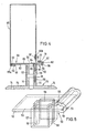
- the holding part 10 consists of a C-profile 11, from the flat middle plate 12 of which two elongate holders 13 extend upwards for fastening to a superstructure.
- Flanges 14, 15, which delimit a cavity 16, are formed on the longitudinal edges of the central plate 12.
- the flange 15 runs at a distance from the inner surface of the central plate 12 parallel to the latter, while the flange 14 is folded inward at its inner free edge to form a rib 17.
- An approximately semicircular groove 18 is formed along the vertical central axis of the central plate 12.
- a rotatable clamping part 19 is loosely inserted into this groove 18 and is designed as an eccentric rod with a circumferential surface that is not radially symmetrical with respect to the axis of rotation.
- the eccentric rod can extend over the entire length or a considerable part of the length of the central plate 12. From the upper end of the eccentric rod, a head piece 20 protrudes at right angles outside the groove 18, which has an inner polygon 21 for attaching an Allen key and a stop surface 22 has.
- the eccentric rod of the clamping part 19 can be oval in cross section or round with two flattened opposite sides. On its circumferential surface it is provided in the region of large diameter with transverse parallel cutting edges 100, which can be seen in the illustration according to FIG. 3 with the clamping part 101, which has a handle 102 protruding approximately at right angles from the eccentric rod 103 at its upper end. The handle 102 extends perpendicular to the axis of the largest diameter of the eccentric rod 103 of the clamping part 101.
- a mounting part 25 with double T-profile is attached hanging.
- the upper flat plate 26 of the mounting part 25 is narrower than the cavity 16 of the C-profile 11.
- the upper plate 26 is inserted obliquely laterally into the cavity 16 of the C-profile 11 and, after being aligned parallel to the inner surface of the central plate 12, is pushed against the flange 14.
- the rib 17 engages in the groove 27, while the edge web 28 of the plate 26 comes to rest against the horizontal part of the flange 14. In this way, a lateral displacement protection is achieved.
- the clamping part 19 is loosely inserted into the groove 18, the larger diameter of the non-circular eccentric rod being aligned parallel to the central plate 12 of the C-profile 11 and the upper plate 26 of the mounting part 25.
- the head piece 20 is pivoted, as a result of which the large diameter of the rod (as shown in FIG. 1) is transversely and the stop surface 22 in the tensioned state shortly after the dead center of the rotary movement on the top plate 26 of the Mounting part 25 strikes.
- the rod now presses with its larger diameter against the bottom of the groove 18 and against the surface of the plate 26, so that the upper plate 26 is pressed against the flanges 14, 15 and the engagement of the rib 17 in the groove 27 is ensured.
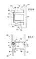
- FIGS 2 and 3 illustrate a facade substructure, which can be made of aluminum.
- the mounting part 30 is provided on a long rail and is designed in cross-section J-shaped with a plate 33 which has a longitudinally bent edge 31 and opposite a longitudinally straight edge 32. From the plate 33 of the J-profile go up two angle rails 34 which have oppositely directed fastening legs 34a for fastening facade panels or the like.
- the L-shaped bent edge 31, the free leg 31a of which is arranged parallel to the flat surface of the plate 33, has at its end an inward upturn which extends over the entire length of the mounting part 30 and a projecting rib 35 forms.
- a longitudinal rib 36 is also located on the straight edge 32. It points in the same direction as the rib 35, namely against the two fastening legs 34a.
- a holding part 40 can be clamped with the mounting part 30.
- This also has a J-shaped cross section with a bent edge 41 and a straight edge 42 and an inwardly directed rib 45 at the end of the bent edge 41 and a longitudinal rib 46 at the end of the straight edge 42.
- the ribs 45 and 46 are directed in the same direction .
- the holding part 40 is designed as an axially short piece of metal (FIG. 3) and in the middle of its plate 43 there is a longitudinally approximately semicircular groove 44 which receives the rod of the clamping part 101.
- a vertically directed tab 68 is formed on the plate 43, which is provided with toothed side surfaces 69 and with a slot hole 47 which is transverse to the course of the toothings.
- the holding part 40 is simply pushed laterally onto the mounting part 30 such that the straight edge 42 engages in the bent edge 31 of the mounting part 30 and the bent edge 41 receives the straight edge 32 of the mounting part 30.
- the ribs 45 and 46 of the holding part 40 engage behind the ribs 35 and 36 of the mounting part 30.
- An angle piece 48 is fastened with its one leg 48b to the masonry 29 or the like with the aid of fastening bolts 23 inserted through the slot hole 49a (FIG. 2 ). Then the tab 68 on the leg 48a by means of the Slotted holes 47, 49 are inserted through bolts to fix the holding part 40. Subsequently, the assembly part 30 is assembled and clamped with the holding part 40 as previously described.
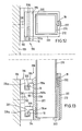
- the example in FIG. 4 is a light box holder with a J-shaped holding part 50 and a J-shaped mounting part 60.
- the holding part 50 consists of a straight plate 53, one edge 52 of which runs straight and the other edge 51 of which is bent like a walking stick .
- the edge 51 is provided at the transition to the flat plate 53 with a longitudinal step 54 and in the region of its free end, which is provided at a distance above the surface of the plate 53, there is a semicircular groove 55 near the step 54 Receiving the clamping part 19.
- the plate 53 is provided outside its center with a cross-shaped opening 56 (FIG. 5), to which a base box 57 adjoins at the bottom, which has longitudinal semicircular grooves 58 in two mutually opposite walls which are open to the outside .
- the base box 57 is clamped with the aid of a clamping part 19 inserted into a groove 58 from above with a straight tube 59 pushed onto the base box 57, so that the holding part 50 and the tube 59 form a coaxial unit.
- the lower open end of the tube 59 is pushed onto an upwardly directed nozzle 71 of a bracket 70.
- the cross-sectional profile of the socket 71 corresponds to that of the base box 57.
- a clamping part 19 is also inserted into an outwardly open semicircular groove 72 for bracing the socket 71 with the pipe 59.
- the console 70 has a large-area base plate 73, which can be circular or angular and which is made with the aid of fastening loops chern 74 allows a connection to any surface.
- the mounting part 60 is placed against the surface of the plate 53 of the holding part 50.
- This also consists of a flat plate 63, the dimensions of which correspond approximately to the plate 53 of the holding part 50 and also has a bent edge 61 and a straight edge 62.
- the straight edge 62 is provided at its end with a longitudinally extending rib 66 pointing downwards which fits behind the step 54 of the bent edge 51 of the holding part 50.
- the clamping part 19 acts against the top of the straight edge 62 of the mounting part 60.
- An opening 64 of the plate 63 is aligned with the opening 56 of the base box 57 and serves for the passage of electrical installations which are guided downward through the base box 57 and the connecting piece 71.
- the bent edge 61 of the mounting part 60 fits around the straight edge 52 of the holding part 50.
- the fork rail 63 receives an angled portion 65a of a transparent box structure 65, the other end 65b of which is screwed, for example, to an upwardly projecting arm 67 of the mounting part 60.
- the plates 53 and 63 lie close together and the scope for adjusting the eccentric clamping part 19 is between the top of the straight edge 62 of the mounting part 60 and the inner surface of the bent part NEN edge 51. In this way, the box structure 65 is stable and shockproof on the substructure.
- FIG. 6 shows a substructure which is suitable for fastening privacy screens or awnings.
- FIG. 6 shows an arrangement of privacy screens 82 on motorways.
- a holding part 80 with a J-shaped cross-section is formed on the underside of a hollow profile rail 81 to which the privacy slats 82 are fastened.
- the lower wall of the hollow profile rail 81 forms the flat plate 83 with a straight edge 84 and an opposite bent edge 85.
- the plate 83 is provided with the semicircular groove 86 for receiving the clamping part 19.
- the bent edge 85 terminates in an elongated end part 85a, the inner surface of which diverges outwards from the lower surface of the wall 83.
- end part 85a On the outer edge of the end part 85a there is an inward projection with an inclined surface 88 which rises from the outside inwards and which ends at a step 87.
- the end part 85a of the bent edge 85 becomes thinner in the direction of the step 87, so that there is a certain spring action transversely to the plate 83.
- the J profile of the mounting part 90 is formed on the top wall 92 of a beam 91 with a square cross section.
- the top wall 92 is extended in the same plane by a plate 93 of the mounting part 90.
- the wall 93 has in the region of the upper wall 92 an upwardly directed bent edge 94 and on its straight edge 95 a resilient strip 96 is formed, which is directed downward and faces the bent edge 94.
- the resilient strip 96 tapers in Transverse direction strong, which gives it a wedge-shaped cross-section.
- the beam 91 is guided laterally against the holding part 80 in such a way that the resilient strip 96 slides over the inclined surface 88 of the projection of the bent edge 85 of the holding part 80 and engages behind the step 87 with its edge 96b when the bent edge 94 of the mounting part 90 includes the straight edge 84 of the holding part 80.
- the locking is achieved in addition to the clipping on the sliding mounting part 90 by the clamping part 19 and its clamping action.
- FIGS. 7, 8 and 9 illustrate schematic end views of fastening devices which are suitable, for example, for attaching hinge bolts or any other movable or immovable components and work with only one abutment.
- the holding part 110 is provided on a hanging rail 111.
- a wide groove 113 with a rectangular cross section is machined into its one side surface.
- the mounting part 115 can be formed from an arbitrarily shaped block 116 which has a slot 117 in its upper half approximately in its longitudinal center plane with a closed bottom 118.
- the one side wall of the slot 117 forms the abutment and contains a groove 119 with a semicircular cross section for receiving the clamping part 19 and the opposite side wall is provided in the mouth region of the slot 117 with a rib 120 facing the groove 119.
- the slot width between the end face of the rib 120 and the opposite edge corresponds to the thickness of the edge region 112, so that the holding part 110 can penetrate into the closed bottom 118 of the slot 117 until the end face thereof stops.
- the eccentric rod of the clamping part 19 presses against the back surface of the edge region 112 and the engaging locking projections 113, 120 are pressed against one another in a force-locking manner and thereby fixed.
- the rib 120 engages in the groove 113, so that the holding part 110 is locked in the mounting part 115.
- the block 116 can have an arbitrarily shaped opening 121 for receiving any element to be attached.
- FIG. 8 shows a construction of a tensioning device similar to FIG. 7.
- the holding part 125 is formed on a rail 126 which has a corner region which is U-shaped in cross section.
- the U-profile accommodates half of an assembly part 130.
- a longitudinal groove 128 with a rectangular cross section is formed on its outward-facing surface, which creates a hook profile 129 with a rounded end face at the end of the leg 127.
- the block-like mounting part 130 has a slot 131 with a closed one Floor 132, which is provided parallel to the longitudinal center plane next to this.
- One wall of the slot serves as an abutment and is equipped with a semicircular groove 133, which receives the clamping part 19 and the other wall is provided with a rib 134 projecting inward over its surface, which is adapted to the groove 128 of the holding part 125 and in this penetrates when the clamping part 19 is tensioned.
- the back surface of the block-like mounting part 130 is pressed against the leg 127 of the rail 126 in the tensioned state, so that it acts as an abutment and stabilizes the overall structure.
- a block 145 of a mounting part 150 is inserted into a U-profile 139 of a holding part 140.
- the block 145 with an approximately rectangular cross section is provided on one side with a semicircular groove 146 for receiving the clamping part 19 and on the opposite side with a longitudinal groove 147 of rectangular cross section.
- a longitudinal rib 148 engages in the groove 147 on the inner surface of a wall of the U-profile 139 of the holding part 140 when the clamping part 19 is tightened against the opposite wall of the holding part 140 serving as an abutment and the parts 140, 150 are clamped together are.
- Figure 10 is similar to the example of Figure 9.
- a cross-sectionally U-shaped mounting part 155 is provided on the inner surface of its one wall 156 in the area of the closed wall 157 with a longitudinal groove 158 and on the inner surface of the opposite wall 159 at a slightly greater distance to the closed wall 157 a semicircular groove 161 for receiving of the clamping part 19.
- the holding part 160 which can be fastened to any, for example vertical, support structure, is designed as an elongated profile body which is formed from a plate 162 with edge flanges 163 projecting on the same side and a longitudinally extending central center structure 164.
- the center structure 164 each includes a wide channel into which the walls 156 and 159 of the mounting part 155 protrude.
- the rib 166 After clamping the clamping part 19 in the groove 161 against the adjacent wall 167 of the center structure 164, the rib 166 is pressed into the groove 158 and the wall 159 is pressed away from the adjacent wall 167 of the center structure 164, so that it acts as a pressure bearing against the lower flange 163 is pressed.
- the entire arrangement is highly resilient.
- a holding part 170 is provided with two parallel rails 171, 172 hanging vertically downwards, which are connected to one another by a horizontal wall 173.
- Each rail 171, 172 has a rib 174, 175 and both ribs face in the same direction.
- a longitudinal profile strand 176 is provided, which forms a semicircular groove 177, which is open against the rib 174 and receives the clamping part 19.
- a slot 178 through which a rail 181 of a mounting part 180 can be inserted so that the rib 174 engages in a groove 182 with a rectangular cross-section when the clamping part 19 is approximately diametrical opposite to groove 182 and rib 174 against the back surface of the rail 181.
- the rib 175 of the rail 172 also engages in a rectangular groove 186 of the rail 187 of the mounting part 180.
- the two rails 181 and 187 of the mounting part 180 are connected to one another by a wall or a web 188.
- FIGS. 12 and 13 are an example of a substructure for a railing, in which a further embodiment of the tensioning device is used.
- a holding part 190 is fastened to a vertical wall 189 by means of bolts 191.
- the holding part 190 has on a plate 192 two mutually parallel L-shaped angled webs 193, 194, the free legs 193a and 194a of which are directed upwards in the same direction. With the surface of the plate 192, the legs 193a and 194a delimit a cavity which is delimited by walls which are perpendicular to one another and is open at the top.
- a mounting part 200 is provided on a wall 201 of a bushing 202 with an approximately square cross section and a perforated bottom 203.
- the mounting part 200 also has L-shaped angled webs 204, 205, the free legs 204a and 205a of which are directed opposite to the legs 193a and 194a of the holding part 190 and are suspended in their cavities (FIG. 13).
- Semicircular grooves 206, 207 are formed on the inner surface of the free legs 204a, 205a and serve to receive the clamping parts 19.
- the clamping parts 19 act ge against the inner surface of the legs 193a, 194a of the holding part 190 and hold the socket on the holding part.
- a rib 208 is formed on the outer surface of the wall 201 of the bush 202, which rib runs parallel to the grooves 206, 207 and which has an outer edge 193b of the upper web 193 as a stop interacts against a displacement of the holding part 190 and the mounting part 200 transversely to their longitudinal axis.
- the socket 202 is open at the top.
- a railing tube 210 with a likewise square cross section can be inserted into this opening.
- FIGS. 14 and 15 show the fastening of a mounting part 230 which can be used as a facade holder to a holding part 220 which is a facade profile.
- the mounting part 230 consists of an extruded profile with an L-shaped cross section with two mutually perpendicular strip parts 231 and 232, one of which strip part 231 is generally J-shaped and has a straight edge 234 and a bent edge 233.
- the bent edge 233 forms a hook.
- the straight edge 234 starts from a strip-shaped intermediate part 235 without deflection and is provided at its outermost end with a longitudinal rib 236 which is directed opposite the hook of the bent edge 233.
- the holding part 220 is designed in cross section as an H-profile with oppositely directed fastening legs 221 for fastening facade panels or the like.
- a strip 223 which are aligned parallel to the fastening legs 221 and form a T-profile with the associated web 222.
- Only one leg 223a of each T-profile is used to fasten the mounting part 230.
- the other leg is available if the mounting part 230 is to be attached to the holding part 220 from the other side, in order to fasten the holding part 220 to an offset fastening surface to enable.
- Each leg 223a is provided on its underside facing the plate 224 with a rib 226 at the edge which delimits a groove.
- the mounting part 230 is pushed laterally into the holding part 220, as the arrow A in FIG. 14 shows.
- the hook of the bent edge 233 grips the leg 223a and the rib 236 engages behind the rib 226, the clamping part 101 is inserted into the groove 237 and rotated into the locking position shown in FIG. 15, in which the handle 102 lies against the bar 223.
- the facade holder is secured by the tensioning device.
- the bent edge 233 of the mounting part 230 is free of a rib.
- the hook can also be provided with an inwardly directed rib, which is the rib 226 of the leg 223a of the lei step 223.
- FIG. 16 illustrates a tensioning device in the case of a facade profile, in which the mounting part 250 and the holding part 240 are configured similarly to those in FIGS. 14, 15.
- the rib formation of one part and the complementary formation of the other part consist of toothed surface profiles 246 and 256.
- This has the essential advantage that the end position of the holding part 240 and the mounting part 250 is not defined unchangeably from the outset, but can be changed depending on the intended use without the locking against transverse displacement in the locked state of the tensioning device being impaired thereby.
- the holding part 240 is designed as an aluminum cassette with a U-shaped cross section, from the base web 241 of which two T-shaped strips 243 are directed outwards on the same side. Only the leg 243a acts as an abutment for the straight edge 256 and the bent edge 253 of the holding part 250 when the clamping part 101 has assumed its locked position.
- the mounting part 250 is fastened by means of a bolt 255 to an angle piece 257, which is used to attach the arrangement to a wall or the like.
Landscapes
- Engineering & Computer Science (AREA)
- Architecture (AREA)
- General Engineering & Computer Science (AREA)
- Civil Engineering (AREA)
- Structural Engineering (AREA)
- Mechanical Engineering (AREA)
- Clamps And Clips (AREA)
Priority Applications (1)
| Application Number | Priority Date | Filing Date | Title |
|---|---|---|---|
| EP91118981A EP0473207B1 (fr) | 1988-06-28 | 1989-06-24 | Dispositif de serrage |
Applications Claiming Priority (2)
| Application Number | Priority Date | Filing Date | Title |
|---|---|---|---|
| DE8808243U DE8808243U1 (de) | 1988-06-28 | 1988-06-28 | Spannvorrichtung |
| DE8808243U | 1988-06-28 |
Related Child Applications (1)
| Application Number | Title | Priority Date | Filing Date |
|---|---|---|---|
| EP91118981.9 Division-Into | 1989-06-24 |
Publications (3)
| Publication Number | Publication Date |
|---|---|
| EP0348853A2 true EP0348853A2 (fr) | 1990-01-03 |
| EP0348853A3 EP0348853A3 (en) | 1990-11-14 |
| EP0348853B1 EP0348853B1 (fr) | 1993-05-19 |
Family
ID=6825400
Family Applications (2)
| Application Number | Title | Priority Date | Filing Date |
|---|---|---|---|
| EP89111549A Expired - Lifetime EP0348853B1 (fr) | 1988-06-28 | 1989-06-24 | Tendeur |
| EP91118981A Expired - Lifetime EP0473207B1 (fr) | 1988-06-28 | 1989-06-24 | Dispositif de serrage |
Family Applications After (1)
| Application Number | Title | Priority Date | Filing Date |
|---|---|---|---|
| EP91118981A Expired - Lifetime EP0473207B1 (fr) | 1988-06-28 | 1989-06-24 | Dispositif de serrage |
Country Status (2)
| Country | Link |
|---|---|
| EP (2) | EP0348853B1 (fr) |
| DE (3) | DE8808243U1 (fr) |
Cited By (3)
| Publication number | Priority date | Publication date | Assignee | Title |
|---|---|---|---|---|
| EP0826850A2 (fr) * | 1996-08-31 | 1998-03-04 | Dietmar Houben | Elément porteur pour façade |
| EP1406021A1 (fr) * | 2002-09-11 | 2004-04-07 | Dietmar Houben | Dispositif à fixation |
| DE202020102247U1 (de) | 2020-04-22 | 2020-06-04 | SCHLÜHER M + K GmbH & Co.KG | Befestigungsvorrichtung und Fassadenkonstruktion hiermit |
Families Citing this family (4)
| Publication number | Priority date | Publication date | Assignee | Title |
|---|---|---|---|---|
| EP0667461B1 (fr) * | 1994-02-09 | 1997-05-28 | Pcm Willen S.A. | Assemblage de précision entre deux pièces |
| AUPO269596A0 (en) * | 1996-10-01 | 1996-10-24 | Sunbum Pty. Limited | Removable surf fin system |
| US20030092333A1 (en) | 2001-11-13 | 2003-05-15 | Mccausland Bill | Removable and adjustable surf fin system |
| CN113530264B (zh) * | 2021-07-05 | 2022-11-04 | 中建一局集团建设发展有限公司 | 一种单元幕墙立柱间隙调节器及其操作方法 |
Citations (4)
| Publication number | Priority date | Publication date | Assignee | Title |
|---|---|---|---|---|
| GB118106A (en) * | 1916-05-29 | 1919-11-13 | Tage Edvard Blum | An Improved Device for Holding or Gripping Plates or the like. |
| US3234702A (en) * | 1960-12-27 | 1966-02-15 | Georgia Marble Co | Anchoring system for the installation of slabs on vertical and overhead surfaces |
| US3356395A (en) * | 1965-07-27 | 1967-12-05 | Unistrut Corp | Adjustable clamp fitting |
| DE2949436A1 (de) * | 1979-12-08 | 1981-06-11 | Dietmar 5600 Wuppertal Houben | Spannvorrichtung |
Family Cites Families (1)
| Publication number | Priority date | Publication date | Assignee | Title |
|---|---|---|---|---|
| US3975805A (en) * | 1975-08-25 | 1976-08-24 | International Electronic Research Corporation | Slide guide retainer |
-
1988
- 1988-06-28 DE DE8808243U patent/DE8808243U1/de not_active Expired
-
1989
- 1989-06-24 EP EP89111549A patent/EP0348853B1/fr not_active Expired - Lifetime
- 1989-06-24 DE DE8989111549T patent/DE58904398D1/de not_active Expired - Fee Related
- 1989-06-24 DE DE58909241T patent/DE58909241D1/de not_active Expired - Fee Related
- 1989-06-24 EP EP91118981A patent/EP0473207B1/fr not_active Expired - Lifetime
Patent Citations (4)
| Publication number | Priority date | Publication date | Assignee | Title |
|---|---|---|---|---|
| GB118106A (en) * | 1916-05-29 | 1919-11-13 | Tage Edvard Blum | An Improved Device for Holding or Gripping Plates or the like. |
| US3234702A (en) * | 1960-12-27 | 1966-02-15 | Georgia Marble Co | Anchoring system for the installation of slabs on vertical and overhead surfaces |
| US3356395A (en) * | 1965-07-27 | 1967-12-05 | Unistrut Corp | Adjustable clamp fitting |
| DE2949436A1 (de) * | 1979-12-08 | 1981-06-11 | Dietmar 5600 Wuppertal Houben | Spannvorrichtung |
Cited By (4)
| Publication number | Priority date | Publication date | Assignee | Title |
|---|---|---|---|---|
| EP0826850A2 (fr) * | 1996-08-31 | 1998-03-04 | Dietmar Houben | Elément porteur pour façade |
| EP0826850A3 (fr) * | 1996-08-31 | 2000-08-23 | Dietmar Houben | Elément porteur pour façade |
| EP1406021A1 (fr) * | 2002-09-11 | 2004-04-07 | Dietmar Houben | Dispositif à fixation |
| DE202020102247U1 (de) | 2020-04-22 | 2020-06-04 | SCHLÜHER M + K GmbH & Co.KG | Befestigungsvorrichtung und Fassadenkonstruktion hiermit |
Also Published As
| Publication number | Publication date |
|---|---|
| DE8808243U1 (de) | 1988-08-18 |
| EP0348853A3 (en) | 1990-11-14 |
| EP0473207A3 (en) | 1992-09-30 |
| DE58904398D1 (de) | 1993-06-24 |
| EP0473207A2 (fr) | 1992-03-04 |
| EP0348853B1 (fr) | 1993-05-19 |
| DE58909241D1 (de) | 1995-06-22 |
| EP0473207B1 (fr) | 1995-05-17 |
Similar Documents
| Publication | Publication Date | Title |
|---|---|---|
| DE2618442C2 (de) | Stütze für ein Geländer oder dergleichen | |
| DE10136681C2 (de) | Rahmengestell | |
| DE102009012438B4 (de) | Pfostenverbinder | |
| EP0945577A2 (fr) | Dispositif de support d'encadrements pour portes ou fenêtres à la périphérie d'une ouverture de paroi | |
| DE202012012290U1 (de) | Befestigungsvorrichtung zur Befestigung plattenförmiger Bauteile | |
| EP2060699B1 (fr) | Dispositif de fixation d'éléments de revêtement ou structure de support pour éléments de revêtement | |
| EP3175127A1 (fr) | Raccord d'angle pour éléments profilés en forme de barre | |
| WO2020049374A1 (fr) | Ferrure d'ajustage et système de support pour modules solaires | |
| DE3048152C2 (de) | Plattenhalterung für Fassaden- oder Dachkonstruktionen | |
| DE69210796T3 (de) | Klammer, insbesondere zur Befestigung von Heizkörpern | |
| EP0348853B1 (fr) | Tendeur | |
| DE2610998B2 (de) | Halterung zur Befestigung von Bekleidungsplatten vor einer Bauwerkswand | |
| EP3241974A1 (fr) | Système pour un joint d'étanchéité, en particulier pour un joint de seuil ou pour un joint de portes s'abaissant automatiquement | |
| DE19722778C1 (de) | Verankerungseinheit | |
| DE3604585A1 (de) | Befestigungsvorrichtung fuer eine fassadenverkleidung | |
| AT518364B1 (de) | Unterkonstruktion für ein Bauwerk | |
| EP2236693B1 (fr) | Support à isolation thermique pour éléments de revêtement | |
| DE4408419A1 (de) | Montageschiene zur Befestigung von Rohren oder dergleichen Gegenständen | |
| DE102019122106B3 (de) | Zaunerweiterungsvorrichtung | |
| DE202006007455U1 (de) | Zaunelement | |
| DE29508686U1 (de) | Bausatz zum Erstellen von Umkleidekabinen, Trennwänden u.dgl. | |
| DE102020101750A1 (de) | Eindrehanker, Anordnung umfassend ein Rahmenprofil und den Eindrehanker und Montageverfahren | |
| DE2949436A1 (de) | Spannvorrichtung | |
| DE3013715C2 (de) | Klemmbefestigung einer elektrischen Einbauleuchte | |
| DE3814535A1 (de) | Laufvorrichtung fuer eine haengende ein- oder mehrfluegelige schiebewand |
Legal Events
| Date | Code | Title | Description |
|---|---|---|---|
| PUAI | Public reference made under article 153(3) epc to a published international application that has entered the european phase |
Free format text: ORIGINAL CODE: 0009012 |
|
| AK | Designated contracting states |
Kind code of ref document: A2 Designated state(s): BE CH DE FR GB IT LI NL |
|
| RHK1 | Main classification (correction) |
Ipc: E04B 2/88 |
|
| PUAL | Search report despatched |
Free format text: ORIGINAL CODE: 0009013 |
|
| AK | Designated contracting states |
Kind code of ref document: A3 Designated state(s): BE CH DE FR GB IT LI NL |
|
| 17P | Request for examination filed |
Effective date: 19901115 |
|
| 17Q | First examination report despatched |
Effective date: 19910425 |
|
| GRAA | (expected) grant |
Free format text: ORIGINAL CODE: 0009210 |
|
| AK | Designated contracting states |
Kind code of ref document: B1 Designated state(s): BE CH DE FR GB IT LI NL |
|
| XX | Miscellaneous (additional remarks) |
Free format text: TEILANMELDUNG 91118981.9 EINGEREICHT AM 24/06/89. |
|
| ITF | It: translation for a ep patent filed | ||
| REF | Corresponds to: |
Ref document number: 58904398 Country of ref document: DE Date of ref document: 19930624 |
|
| ET | Fr: translation filed | ||
| GBT | Gb: translation of ep patent filed (gb section 77(6)(a)/1977) |
Effective date: 19930621 |
|
| PLBE | No opposition filed within time limit |
Free format text: ORIGINAL CODE: 0009261 |
|
| STAA | Information on the status of an ep patent application or granted ep patent |
Free format text: STATUS: NO OPPOSITION FILED WITHIN TIME LIMIT |
|
| 26N | No opposition filed | ||
| REG | Reference to a national code |
Ref country code: GB Ref legal event code: IF02 |
|
| PGFP | Annual fee paid to national office [announced via postgrant information from national office to epo] |
Ref country code: NL Payment date: 20030617 Year of fee payment: 15 |
|
| PGFP | Annual fee paid to national office [announced via postgrant information from national office to epo] |
Ref country code: BE Payment date: 20030702 Year of fee payment: 15 |
|
| PG25 | Lapsed in a contracting state [announced via postgrant information from national office to epo] |
Ref country code: BE Free format text: LAPSE BECAUSE OF NON-PAYMENT OF DUE FEES Effective date: 20040630 |
|
| BERE | Be: lapsed |
Owner name: *HOUBEN DIETMAR Effective date: 20040630 |
|
| PG25 | Lapsed in a contracting state [announced via postgrant information from national office to epo] |
Ref country code: NL Free format text: LAPSE BECAUSE OF NON-PAYMENT OF DUE FEES Effective date: 20050101 |
|
| NLV4 | Nl: lapsed or anulled due to non-payment of the annual fee |
Effective date: 20050101 |
|
| PG25 | Lapsed in a contracting state [announced via postgrant information from national office to epo] |
Ref country code: IT Free format text: LAPSE BECAUSE OF NON-PAYMENT OF DUE FEES;WARNING: LAPSES OF ITALIAN PATENTS WITH EFFECTIVE DATE BEFORE 2007 MAY HAVE OCCURRED AT ANY TIME BEFORE 2007. THE CORRECT EFFECTIVE DATE MAY BE DIFFERENT FROM THE ONE RECORDED. Effective date: 20050624 |
|
| PGFP | Annual fee paid to national office [announced via postgrant information from national office to epo] |
Ref country code: DE Payment date: 20070725 Year of fee payment: 19 |
|
| PGFP | Annual fee paid to national office [announced via postgrant information from national office to epo] |
Ref country code: CH Payment date: 20070724 Year of fee payment: 19 |
|
| PGFP | Annual fee paid to national office [announced via postgrant information from national office to epo] |
Ref country code: FR Payment date: 20070718 Year of fee payment: 19 |
|
| PGFP | Annual fee paid to national office [announced via postgrant information from national office to epo] |
Ref country code: GB Payment date: 20080624 Year of fee payment: 20 |
|
| REG | Reference to a national code |
Ref country code: CH Ref legal event code: PL |
|
| REG | Reference to a national code |
Ref country code: FR Ref legal event code: ST Effective date: 20090228 |
|
| PG25 | Lapsed in a contracting state [announced via postgrant information from national office to epo] |
Ref country code: DE Free format text: LAPSE BECAUSE OF NON-PAYMENT OF DUE FEES Effective date: 20090101 |
|
| PG25 | Lapsed in a contracting state [announced via postgrant information from national office to epo] |
Ref country code: CH Free format text: LAPSE BECAUSE OF NON-PAYMENT OF DUE FEES Effective date: 20080630 Ref country code: LI Free format text: LAPSE BECAUSE OF NON-PAYMENT OF DUE FEES Effective date: 20080630 |
|
| REG | Reference to a national code |
Ref country code: GB Ref legal event code: PE20 Expiry date: 20090623 |
|
| PG25 | Lapsed in a contracting state [announced via postgrant information from national office to epo] |
Ref country code: FR Free format text: LAPSE BECAUSE OF NON-PAYMENT OF DUE FEES Effective date: 20080630 |
|
| PG25 | Lapsed in a contracting state [announced via postgrant information from national office to epo] |
Ref country code: GB Free format text: LAPSE BECAUSE OF EXPIRATION OF PROTECTION Effective date: 20090623 |