EP0348853A2 - Spannvorrichtung - Google Patents
Spannvorrichtung Download PDFInfo
- Publication number
- EP0348853A2 EP0348853A2 EP89111549A EP89111549A EP0348853A2 EP 0348853 A2 EP0348853 A2 EP 0348853A2 EP 89111549 A EP89111549 A EP 89111549A EP 89111549 A EP89111549 A EP 89111549A EP 0348853 A2 EP0348853 A2 EP 0348853A2
- Authority
- EP
- European Patent Office
- Prior art keywords
- edge
- rib
- formation
- clamping
- holding part
- Prior art date
- Legal status (The legal status is an assumption and is not a legal conclusion. Google has not performed a legal analysis and makes no representation as to the accuracy of the status listed.)
- Granted
Links
Images


Classifications
-
- E—FIXED CONSTRUCTIONS
- E04—BUILDING
- E04F—FINISHING WORK ON BUILDINGS, e.g. STAIRS, FLOORS
- E04F13/00—Coverings or linings, e.g. for walls or ceilings
- E04F13/07—Coverings or linings, e.g. for walls or ceilings composed of covering or lining elements; Sub-structures therefor; Fastening means therefor
- E04F13/08—Coverings or linings, e.g. for walls or ceilings composed of covering or lining elements; Sub-structures therefor; Fastening means therefor composed of a plurality of similar covering or lining elements
- E04F13/0801—Separate fastening elements
- E04F13/0803—Separate fastening elements with load-supporting elongated furring elements between wall and covering elements
- E04F13/081—Separate fastening elements with load-supporting elongated furring elements between wall and covering elements with additional fastening elements between furring elements and covering elements
-
- F—MECHANICAL ENGINEERING; LIGHTING; HEATING; WEAPONS; BLASTING
- F16—ENGINEERING ELEMENTS AND UNITS; GENERAL MEASURES FOR PRODUCING AND MAINTAINING EFFECTIVE FUNCTIONING OF MACHINES OR INSTALLATIONS; THERMAL INSULATION IN GENERAL
- F16B—DEVICES FOR FASTENING OR SECURING CONSTRUCTIONAL ELEMENTS OR MACHINE PARTS TOGETHER, e.g. NAILS, BOLTS, CIRCLIPS, CLAMPS, CLIPS OR WEDGES; JOINTS OR JOINTING
- F16B2/00—Friction-grip releasable fastenings
- F16B2/02—Clamps, i.e. with gripping action effected by positive means other than the inherent resistance to deformation of the material of the fastening
- F16B2/18—Clamps, i.e. with gripping action effected by positive means other than the inherent resistance to deformation of the material of the fastening using cams, levers, eccentrics, or toggles
Definitions
- the invention relates to a clamping device for connecting a holding part to a mounting part, in which an eccentric rod arranged between two opposite surfaces braces both parts against abutments as a rotatable clamping part.
- the holding part is designed as a C-profile rail and the mounting part consists of a plate which is inserted centrally into the C-profile and clamped in a longitudinal groove with the aid of the eccentric rod is. If the width of the mounting part approximately corresponds to the width of the cavity of the holding part - which is favorable in order to avoid transverse displacements of the two parts relative to one another, the mounting part must be inserted axially into the holding part from one end. This is the case with holding parts that are several meters long Eg used in roof structures, cumbersome and in some cases not feasible due to space constraints.
- the width of the mounting part was dimensioned so small with respect to the C-profile cavity of the holding part that the mounting part could be inserted transversely into the C-profile . Since the mounting part is only slightly wider than the longitudinal opening of the C-profile of the holding part, there is a risk that shocks or deformations will cause the mounting part to slip out of the C-profile of the holding part due to assembly errors and the clamping of the two parts will at least partially become ineffective with disadvantageous consequences for the overall construction.
- the invention has for its object to improve a clamping device of the type mentioned so that an easier assembly of the parts and their reliable cohesion are guaranteed.
- the mounting part or the holding part is provided with at least one rib formation parallel to the rod-shaped clamping part, which forms a stop against transverse displacement of the two parts relative to one another with a complementary formation of the other part.
- a known eccentric rod is advantageously used, which has a head piece which, in the tensioned state, strikes against an opposite surface shortly after the dead center of the rotary movement.
- the headpiece can be actuated with the aid of an arm fastened to it, or it can be rotated by inserting an Allen key into an internal polygon in its upper end face.
- the mounting part or the holding part has a cross-section C-profile with two flanges and the one flange of the C-profile is provided with an inwardly directed rib formation, that the other part is designed as a plate and that at least one of the longitudinal edges of the plate-shaped other part overlapped by the two flanges of the C-profile part has the complementary formation for the rib formation.
- the rib formation can consist of a projecting rib and the complementary formation can be formed by a groove on the outer edge of the plate-shaped part, so that the rib engages in the groove and the gradation of the groove engages behind the rib of the other part. Securing against transverse displacement of the two parts relative to one another is achieved, so that the plate-shaped part is so narrow can that it can be inserted laterally into the C-profile of the other part by inclination, without the risk of it slipping out after assembly.
- the mounting part and the holding part have a J-shaped cross-section with a bent and a straight longitudinal edge, that the straight edge of one part is encompassed by the bent edge of the other part and that the straight edge of at least one part has the rib formation which mates with the complementary formation on the bent edge of the other part.
- Such cross-sectional profiling of the mounting part and the holding part is particularly advantageous because both parts can be pushed laterally parallel to one another without any special manipulations and, after tensioning with the aid of the eccentric rod pressing against the surfaces of the J-shaped parts, the bent edges of the two pointing towards opposite sides Parts that form abutments.
- the engagement of the rib formations and the complementary formations also prevents slipping out or shifting of parts relative to one another.
- the rib formations and complementary formations can be formed by folding up the edges of the parts.
- the eccentric rod is advantageously embedded in a longitudinal groove in the middle of one part and engages against the central region of the other part, so that the clamping force is equally effective against both sides.
- the mounting part and the holding part have a J-shaped cross-section with a bent and a straight longitudinal edge, that the straight edge of one part is encompassed by the bent edge of the other part and that the straight edge of one part on the surface facing away from its bent edge has a resilient strip which engages with the rib formation on the bent edge of the other part.
- the rib formation can consist of a single rib which is gripped behind by the edge of the resilient strip.
- Such a construction is also assembled by pushing the parts together laterally, the female connector allowing clipping and, in addition to the clamping force of the eccentric rod, exerting a holding force on the parts connected to one another in such a way that one part can be attached laterally to the other in a hanging manner.
- the holding part has two L-shaped angled webs on the same side, the bends of oppositely directed L-shaped bends on two webs of the mounting part are engaged, that the clamping part between the adjacent Surfaces of the L-shaped bends is arranged and that a rib is formed on one part, the complementary formation of which is an edge of the other part.
- This double bracket with interlocking L-shaped webs can be used cheaply as a substructure for railings
- the mounting part can consist of a socket into which a railing tube is inserted, which is arranged with the aid of a in a longitudinal groove Eccentric rod can be clamped to the socket.
- the holding part can be attached to a console or a rail.
- FIG. 5 Another embodiment of the invention (claim 5) provides that the holding part or the mounting part in cross-section has a J-shape with a bent and a straight longitudinal edge, that the other part has the same directional L-profile leg, which is bent and bent behind the straight edge of the J-shaped part and that at least one of the L-profile legs has a rib formation which engages with the complementary formation of the J-shaped part.
- This design is particularly favorable for facade profiles, whereby the J-shaped part can be a facade holder, which is inserted laterally into the holding part with the two L-profile legs until its straight edge and its bent edge engage behind the L-profile legs.
- the clamping part is then inserted into a groove, which is preferably arranged on the facade holder, and is rotated until it reaches its clamping position, in which the longitudinal axis of its eccentric is approximately perpendicular to the mutually opposite surfaces of the mounting part and the holding part. Installation is quick and easy.
- the facade holder is inserted into the various facade profiles from behind, moved briefly and fixed with the clamping part. Clamping parts with cutting grooves are used at the facade fixed points, while clamping parts without cutting grooves are used at the sliding points.
- the holding part or the mounting part has a body, on one of which Side the rib formation is formed, which engages with the complementary formation on the other part and that the clamping part is arranged approximately diametrically opposite the rib and complementary formations.
- the clamping part is arranged between the ends of opposite surfaces of the mounting part and the holding part and two abutments are required, it is preferably diametrically opposite the point of engagement of the rib formation and complementary formation in this embodiment and clamps both parts against only one abutment together.
- the body with the rib formation can be designed as a hollow or solid block or as a rail and any suspension and fastening devices can be constructed, the cohesion of which is ensured by the engagement of the rib formation with the complementary formation and the clamping part which is effective transversely to this interlocking.
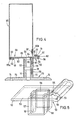
- the holding part 10 consists of a C-profile 11, from the flat middle plate 12 of which two elongate holders 13 extend upwards for fastening to a superstructure.
- Flanges 14, 15, which delimit a cavity 16, are formed on the longitudinal edges of the central plate 12.
- the flange 15 runs at a distance from the inner surface of the central plate 12 parallel to the latter, while the flange 14 is folded inward at its inner free edge to form a rib 17.
- An approximately semicircular groove 18 is formed along the vertical central axis of the central plate 12.
- a rotatable clamping part 19 is loosely inserted into this groove 18 and is designed as an eccentric rod with a circumferential surface that is not radially symmetrical with respect to the axis of rotation.
- the eccentric rod can extend over the entire length or a considerable part of the length of the central plate 12. From the upper end of the eccentric rod, a head piece 20 protrudes at right angles outside the groove 18, which has an inner polygon 21 for attaching an Allen key and a stop surface 22 has.
- the eccentric rod of the clamping part 19 can be oval in cross section or round with two flattened opposite sides. On its circumferential surface it is provided in the region of large diameter with transverse parallel cutting edges 100, which can be seen in the illustration according to FIG. 3 with the clamping part 101, which has a handle 102 protruding approximately at right angles from the eccentric rod 103 at its upper end. The handle 102 extends perpendicular to the axis of the largest diameter of the eccentric rod 103 of the clamping part 101.
- a mounting part 25 with double T-profile is attached hanging.
- the upper flat plate 26 of the mounting part 25 is narrower than the cavity 16 of the C-profile 11.
- the upper plate 26 is inserted obliquely laterally into the cavity 16 of the C-profile 11 and, after being aligned parallel to the inner surface of the central plate 12, is pushed against the flange 14.
- the rib 17 engages in the groove 27, while the edge web 28 of the plate 26 comes to rest against the horizontal part of the flange 14. In this way, a lateral displacement protection is achieved.
- the clamping part 19 is loosely inserted into the groove 18, the larger diameter of the non-circular eccentric rod being aligned parallel to the central plate 12 of the C-profile 11 and the upper plate 26 of the mounting part 25.
- the head piece 20 is pivoted, as a result of which the large diameter of the rod (as shown in FIG. 1) is transversely and the stop surface 22 in the tensioned state shortly after the dead center of the rotary movement on the top plate 26 of the Mounting part 25 strikes.
- the rod now presses with its larger diameter against the bottom of the groove 18 and against the surface of the plate 26, so that the upper plate 26 is pressed against the flanges 14, 15 and the engagement of the rib 17 in the groove 27 is ensured.
- FIGS 2 and 3 illustrate a facade substructure, which can be made of aluminum.
- the mounting part 30 is provided on a long rail and is designed in cross-section J-shaped with a plate 33 which has a longitudinally bent edge 31 and opposite a longitudinally straight edge 32. From the plate 33 of the J-profile go up two angle rails 34 which have oppositely directed fastening legs 34a for fastening facade panels or the like.
- the L-shaped bent edge 31, the free leg 31a of which is arranged parallel to the flat surface of the plate 33, has at its end an inward upturn which extends over the entire length of the mounting part 30 and a projecting rib 35 forms.
- a longitudinal rib 36 is also located on the straight edge 32. It points in the same direction as the rib 35, namely against the two fastening legs 34a.
- a holding part 40 can be clamped with the mounting part 30.
- This also has a J-shaped cross section with a bent edge 41 and a straight edge 42 and an inwardly directed rib 45 at the end of the bent edge 41 and a longitudinal rib 46 at the end of the straight edge 42.
- the ribs 45 and 46 are directed in the same direction .
- the holding part 40 is designed as an axially short piece of metal (FIG. 3) and in the middle of its plate 43 there is a longitudinally approximately semicircular groove 44 which receives the rod of the clamping part 101.
- a vertically directed tab 68 is formed on the plate 43, which is provided with toothed side surfaces 69 and with a slot hole 47 which is transverse to the course of the toothings.
- the holding part 40 is simply pushed laterally onto the mounting part 30 such that the straight edge 42 engages in the bent edge 31 of the mounting part 30 and the bent edge 41 receives the straight edge 32 of the mounting part 30.
- the ribs 45 and 46 of the holding part 40 engage behind the ribs 35 and 36 of the mounting part 30.
- An angle piece 48 is fastened with its one leg 48b to the masonry 29 or the like with the aid of fastening bolts 23 inserted through the slot hole 49a (FIG. 2 ). Then the tab 68 on the leg 48a by means of the Slotted holes 47, 49 are inserted through bolts to fix the holding part 40. Subsequently, the assembly part 30 is assembled and clamped with the holding part 40 as previously described.
- the example in FIG. 4 is a light box holder with a J-shaped holding part 50 and a J-shaped mounting part 60.
- the holding part 50 consists of a straight plate 53, one edge 52 of which runs straight and the other edge 51 of which is bent like a walking stick .
- the edge 51 is provided at the transition to the flat plate 53 with a longitudinal step 54 and in the region of its free end, which is provided at a distance above the surface of the plate 53, there is a semicircular groove 55 near the step 54 Receiving the clamping part 19.
- the plate 53 is provided outside its center with a cross-shaped opening 56 (FIG. 5), to which a base box 57 adjoins at the bottom, which has longitudinal semicircular grooves 58 in two mutually opposite walls which are open to the outside .
- the base box 57 is clamped with the aid of a clamping part 19 inserted into a groove 58 from above with a straight tube 59 pushed onto the base box 57, so that the holding part 50 and the tube 59 form a coaxial unit.
- the lower open end of the tube 59 is pushed onto an upwardly directed nozzle 71 of a bracket 70.
- the cross-sectional profile of the socket 71 corresponds to that of the base box 57.
- a clamping part 19 is also inserted into an outwardly open semicircular groove 72 for bracing the socket 71 with the pipe 59.
- the console 70 has a large-area base plate 73, which can be circular or angular and which is made with the aid of fastening loops chern 74 allows a connection to any surface.
- the mounting part 60 is placed against the surface of the plate 53 of the holding part 50.
- This also consists of a flat plate 63, the dimensions of which correspond approximately to the plate 53 of the holding part 50 and also has a bent edge 61 and a straight edge 62.
- the straight edge 62 is provided at its end with a longitudinally extending rib 66 pointing downwards which fits behind the step 54 of the bent edge 51 of the holding part 50.
- the clamping part 19 acts against the top of the straight edge 62 of the mounting part 60.
- An opening 64 of the plate 63 is aligned with the opening 56 of the base box 57 and serves for the passage of electrical installations which are guided downward through the base box 57 and the connecting piece 71.
- the bent edge 61 of the mounting part 60 fits around the straight edge 52 of the holding part 50.
- the fork rail 63 receives an angled portion 65a of a transparent box structure 65, the other end 65b of which is screwed, for example, to an upwardly projecting arm 67 of the mounting part 60.
- the plates 53 and 63 lie close together and the scope for adjusting the eccentric clamping part 19 is between the top of the straight edge 62 of the mounting part 60 and the inner surface of the bent part NEN edge 51. In this way, the box structure 65 is stable and shockproof on the substructure.
- FIG. 6 shows a substructure which is suitable for fastening privacy screens or awnings.
- FIG. 6 shows an arrangement of privacy screens 82 on motorways.
- a holding part 80 with a J-shaped cross-section is formed on the underside of a hollow profile rail 81 to which the privacy slats 82 are fastened.
- the lower wall of the hollow profile rail 81 forms the flat plate 83 with a straight edge 84 and an opposite bent edge 85.
- the plate 83 is provided with the semicircular groove 86 for receiving the clamping part 19.
- the bent edge 85 terminates in an elongated end part 85a, the inner surface of which diverges outwards from the lower surface of the wall 83.
- end part 85a On the outer edge of the end part 85a there is an inward projection with an inclined surface 88 which rises from the outside inwards and which ends at a step 87.
- the end part 85a of the bent edge 85 becomes thinner in the direction of the step 87, so that there is a certain spring action transversely to the plate 83.
- the J profile of the mounting part 90 is formed on the top wall 92 of a beam 91 with a square cross section.
- the top wall 92 is extended in the same plane by a plate 93 of the mounting part 90.
- the wall 93 has in the region of the upper wall 92 an upwardly directed bent edge 94 and on its straight edge 95 a resilient strip 96 is formed, which is directed downward and faces the bent edge 94.
- the resilient strip 96 tapers in Transverse direction strong, which gives it a wedge-shaped cross-section.
- the beam 91 is guided laterally against the holding part 80 in such a way that the resilient strip 96 slides over the inclined surface 88 of the projection of the bent edge 85 of the holding part 80 and engages behind the step 87 with its edge 96b when the bent edge 94 of the mounting part 90 includes the straight edge 84 of the holding part 80.
- the locking is achieved in addition to the clipping on the sliding mounting part 90 by the clamping part 19 and its clamping action.
- FIGS. 7, 8 and 9 illustrate schematic end views of fastening devices which are suitable, for example, for attaching hinge bolts or any other movable or immovable components and work with only one abutment.
- the holding part 110 is provided on a hanging rail 111.
- a wide groove 113 with a rectangular cross section is machined into its one side surface.
- the mounting part 115 can be formed from an arbitrarily shaped block 116 which has a slot 117 in its upper half approximately in its longitudinal center plane with a closed bottom 118.
- the one side wall of the slot 117 forms the abutment and contains a groove 119 with a semicircular cross section for receiving the clamping part 19 and the opposite side wall is provided in the mouth region of the slot 117 with a rib 120 facing the groove 119.
- the slot width between the end face of the rib 120 and the opposite edge corresponds to the thickness of the edge region 112, so that the holding part 110 can penetrate into the closed bottom 118 of the slot 117 until the end face thereof stops.
- the eccentric rod of the clamping part 19 presses against the back surface of the edge region 112 and the engaging locking projections 113, 120 are pressed against one another in a force-locking manner and thereby fixed.
- the rib 120 engages in the groove 113, so that the holding part 110 is locked in the mounting part 115.
- the block 116 can have an arbitrarily shaped opening 121 for receiving any element to be attached.
- FIG. 8 shows a construction of a tensioning device similar to FIG. 7.
- the holding part 125 is formed on a rail 126 which has a corner region which is U-shaped in cross section.
- the U-profile accommodates half of an assembly part 130.
- a longitudinal groove 128 with a rectangular cross section is formed on its outward-facing surface, which creates a hook profile 129 with a rounded end face at the end of the leg 127.
- the block-like mounting part 130 has a slot 131 with a closed one Floor 132, which is provided parallel to the longitudinal center plane next to this.
- One wall of the slot serves as an abutment and is equipped with a semicircular groove 133, which receives the clamping part 19 and the other wall is provided with a rib 134 projecting inward over its surface, which is adapted to the groove 128 of the holding part 125 and in this penetrates when the clamping part 19 is tensioned.
- the back surface of the block-like mounting part 130 is pressed against the leg 127 of the rail 126 in the tensioned state, so that it acts as an abutment and stabilizes the overall structure.
- a block 145 of a mounting part 150 is inserted into a U-profile 139 of a holding part 140.
- the block 145 with an approximately rectangular cross section is provided on one side with a semicircular groove 146 for receiving the clamping part 19 and on the opposite side with a longitudinal groove 147 of rectangular cross section.
- a longitudinal rib 148 engages in the groove 147 on the inner surface of a wall of the U-profile 139 of the holding part 140 when the clamping part 19 is tightened against the opposite wall of the holding part 140 serving as an abutment and the parts 140, 150 are clamped together are.
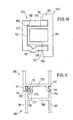
- Figure 10 is similar to the example of Figure 9.
- a cross-sectionally U-shaped mounting part 155 is provided on the inner surface of its one wall 156 in the area of the closed wall 157 with a longitudinal groove 158 and on the inner surface of the opposite wall 159 at a slightly greater distance to the closed wall 157 a semicircular groove 161 for receiving of the clamping part 19.
- the holding part 160 which can be fastened to any, for example vertical, support structure, is designed as an elongated profile body which is formed from a plate 162 with edge flanges 163 projecting on the same side and a longitudinally extending central center structure 164.
- the center structure 164 each includes a wide channel into which the walls 156 and 159 of the mounting part 155 protrude.
- the rib 166 After clamping the clamping part 19 in the groove 161 against the adjacent wall 167 of the center structure 164, the rib 166 is pressed into the groove 158 and the wall 159 is pressed away from the adjacent wall 167 of the center structure 164, so that it acts as a pressure bearing against the lower flange 163 is pressed.
- the entire arrangement is highly resilient.
- a holding part 170 is provided with two parallel rails 171, 172 hanging vertically downwards, which are connected to one another by a horizontal wall 173.
- Each rail 171, 172 has a rib 174, 175 and both ribs face in the same direction.
- a longitudinal profile strand 176 is provided, which forms a semicircular groove 177, which is open against the rib 174 and receives the clamping part 19.
- a slot 178 through which a rail 181 of a mounting part 180 can be inserted so that the rib 174 engages in a groove 182 with a rectangular cross-section when the clamping part 19 is approximately diametrical opposite to groove 182 and rib 174 against the back surface of the rail 181.
- the rib 175 of the rail 172 also engages in a rectangular groove 186 of the rail 187 of the mounting part 180.
- the two rails 181 and 187 of the mounting part 180 are connected to one another by a wall or a web 188.
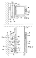
- FIGS. 12 and 13 are an example of a substructure for a railing, in which a further embodiment of the tensioning device is used.
- a holding part 190 is fastened to a vertical wall 189 by means of bolts 191.
- the holding part 190 has on a plate 192 two mutually parallel L-shaped angled webs 193, 194, the free legs 193a and 194a of which are directed upwards in the same direction. With the surface of the plate 192, the legs 193a and 194a delimit a cavity which is delimited by walls which are perpendicular to one another and is open at the top.
- a mounting part 200 is provided on a wall 201 of a bushing 202 with an approximately square cross section and a perforated bottom 203.
- the mounting part 200 also has L-shaped angled webs 204, 205, the free legs 204a and 205a of which are directed opposite to the legs 193a and 194a of the holding part 190 and are suspended in their cavities (FIG. 13).
- Semicircular grooves 206, 207 are formed on the inner surface of the free legs 204a, 205a and serve to receive the clamping parts 19.
- the clamping parts 19 act ge against the inner surface of the legs 193a, 194a of the holding part 190 and hold the socket on the holding part.
- a rib 208 is formed on the outer surface of the wall 201 of the bush 202, which rib runs parallel to the grooves 206, 207 and which has an outer edge 193b of the upper web 193 as a stop interacts against a displacement of the holding part 190 and the mounting part 200 transversely to their longitudinal axis.
- the socket 202 is open at the top.
- a railing tube 210 with a likewise square cross section can be inserted into this opening.
- FIGS. 14 and 15 show the fastening of a mounting part 230 which can be used as a facade holder to a holding part 220 which is a facade profile.
- the mounting part 230 consists of an extruded profile with an L-shaped cross section with two mutually perpendicular strip parts 231 and 232, one of which strip part 231 is generally J-shaped and has a straight edge 234 and a bent edge 233.
- the bent edge 233 forms a hook.
- the straight edge 234 starts from a strip-shaped intermediate part 235 without deflection and is provided at its outermost end with a longitudinal rib 236 which is directed opposite the hook of the bent edge 233.
- the holding part 220 is designed in cross section as an H-profile with oppositely directed fastening legs 221 for fastening facade panels or the like.
- a strip 223 which are aligned parallel to the fastening legs 221 and form a T-profile with the associated web 222.
- Only one leg 223a of each T-profile is used to fasten the mounting part 230.
- the other leg is available if the mounting part 230 is to be attached to the holding part 220 from the other side, in order to fasten the holding part 220 to an offset fastening surface to enable.
- Each leg 223a is provided on its underside facing the plate 224 with a rib 226 at the edge which delimits a groove.
- the mounting part 230 is pushed laterally into the holding part 220, as the arrow A in FIG. 14 shows.
- the hook of the bent edge 233 grips the leg 223a and the rib 236 engages behind the rib 226, the clamping part 101 is inserted into the groove 237 and rotated into the locking position shown in FIG. 15, in which the handle 102 lies against the bar 223.
- the facade holder is secured by the tensioning device.
- the bent edge 233 of the mounting part 230 is free of a rib.
- the hook can also be provided with an inwardly directed rib, which is the rib 226 of the leg 223a of the lei step 223.
- FIG. 16 illustrates a tensioning device in the case of a facade profile, in which the mounting part 250 and the holding part 240 are configured similarly to those in FIGS. 14, 15.
- the rib formation of one part and the complementary formation of the other part consist of toothed surface profiles 246 and 256.
- This has the essential advantage that the end position of the holding part 240 and the mounting part 250 is not defined unchangeably from the outset, but can be changed depending on the intended use without the locking against transverse displacement in the locked state of the tensioning device being impaired thereby.
- the holding part 240 is designed as an aluminum cassette with a U-shaped cross section, from the base web 241 of which two T-shaped strips 243 are directed outwards on the same side. Only the leg 243a acts as an abutment for the straight edge 256 and the bent edge 253 of the holding part 250 when the clamping part 101 has assumed its locked position.
- the mounting part 250 is fastened by means of a bolt 255 to an angle piece 257, which is used to attach the arrangement to a wall or the like.
Landscapes
- Engineering & Computer Science (AREA)
- General Engineering & Computer Science (AREA)
- Architecture (AREA)
- Mechanical Engineering (AREA)
- Civil Engineering (AREA)
- Structural Engineering (AREA)
- Clamps And Clips (AREA)
Abstract
Description
- Die Erfindung betrifft eine Spannvorrichtung zur Verbindung eines Halteteiles mit einem Montageteil, bei der ein zwischen zwei einander gegenüberliegenden Flächen angeordneter Exzenterstab als drehbarer Klemmteil beide Teile gegen Widerlager verspannt.
- Bei einer bekannten derartigen Spannvorrichtung (DE-A-29 49 436) ist das Halteteil als C-Profil-Schiene ausgebildet und das Montageteil besteht aus einer Platte, die zentral in das C-Profil eingelegt und mit Hilfe des Exzenterstabes in einer längslaufenden Nut festgespannt ist. Wenn die Breite des Montageteiles der Breite des Hohlraumes des Halteteiles etwa entspricht - was zur Vermeidung von Querverschiebungen beider Teile relativ zueinander günstig ist, muß das Montageteil von einem Ende her axial in das Halteteil eingeschoben werden. Dies ist bei mehrere Meter langen Halteteilen, wie sie z.B. bei Dachkonstruktionen benutzt werden, umständlich und in manchen Fällen aus Platzgründen gar nicht durchführbar. Um auch in solchen Fällen die an sich günstige Spannvorrichtung mit Exzenterstab benutzen zu können, wurde die Breite des Montageteiles in bezug auf den C-Profil-Hohlraum des Halteteiles so gering bemessen, daß das Montageteil durch Schrägstellung quer in das C-Profil eingesetzt werden konnte. Da das Montageteil dabei nur geringfügig breiter als die Längsöffnung des C-Profils des Halteteiles ist, besteht die Gefahr, daß durch Montagefehler Erschütterungen oder Deformationen das Montageteil aus dem C-Profil des Halteteiles herausrutscht und die Zusammenspannung beider Teile wenigstens teilweise unwirksam wird mit nachteiligen Folgen für die Gesamtkonstruktion.
- Der Erfindung liegt die Aufgabe zugrunde, eine Spannvorrichtung der eingangs erwähnten Art so zu verbessern, daß eine erleichterte Montage der Teile und ihr zuverlässiger Zusammenhalt gewährleistet sind.
- Diese Aufgabe wird erfindungsgemäß dadurch gelöst, daß das Montageteil oder das Halteteil mit mindestens einer zu dem stabförmigen Klemmteil parallelen Rippenformation versehen ist, die mit einer Komplementärformation des anderen Teiles einen Anschlag gegen Querverschiebung der beiden Teile relativ zueinander bildet.
- Die durch die Rippenformation und die Komplementärformation erzielte Sicherung beider Teile gegen Querverschiebung hält das eine Teil auch dann zuverlässig fest, wenn es zur Ermöglichung der Quereinführung in ein wannenförmiges Profil des anderen Teiles verhältnismäßig schmal ist und außerdem sind vielfältige Vari ationen der Querschnittsprofilierung von Montageteil und Halteteil möglich, die ebenfalls ein einfaches seitliches Zusammenschieben von Montageteil und Halteteil an jeder Stelle der Teile zulassen, so daß eine wesentlich vereinfachte und schnellere Montage bei Gewährleistung ihres sicheren Zusammenhaltes nach dem Verspannen möglich ist.
- Vorteilhafterweise wird ein bekannter Exzenterstab verwendet, der ein Kopfstück aufweist, das im gespannten Zustand kurz hinter dem Totpunkt der Drehbewegung gegen eine gegenüberliegende Fläche anschlägt. Das Kopfstück kann mit Hilfe eines an diesem befestigten Armes betätigt werden oder es kann durch Ansetzen eines Imbusschlüssels in einen Innenmehrkant in seiner oberen Stirnseite gedreht werden.
- In vorteilhafter Ausgestaltung der Erfindung (Anspruch 2) ist vorgesehen, daß das Montageteil oder das Halteteil im Querschnitt C-Profil mit zwei Flanschen hat und der eine Flansch des C-Profils mit einer einwärts gerichteten Rippenformation versehen ist, daß das andere Teil als Platte ausgebildet ist und daß wenigstens einer der von den beiden Flanschen des C-Profil-Teiles übergriffenen Längsränder des plattenförmigen anderen Teiles die Komplementärformation für die Rippenformation aufweist. Die Rippenformation kann aus einer vorspringenden Rippe bestehen und die Komplementärformation kann durch eine Rille am äußeren Rand des plattenförmigen Teiles gebildet sein, so daß die Rippe in die Rille eingreift und die Abstufung der Rille die Rippe des anderen Teiles hintergreift. Es wird eine Sicherung gegen Querverschiebung beider Teile relativ zueinander erzielt, so daß der plattenförmige Teil so schmal sein kann, daß er sich durch Schrägstellung seitlich in das C-Profil des anderen Teiles einführen läßt, ohne daß die Gefahr seines Herausrutschens nach der Montage besteht.
- Bei einer anderen Ausführungsform der Erfindung (Anspruch 3) ist vorgesehen, daß das Montageteil und das Halteteil im Querschnitt J-Form mit einem umgebogenen und einem geraden längsverlaufenden Rand haben, daß der gerade Rand des einen Teiles von dem umgebogenen Rand des anderen Teiles umgriffen ist und daß der gerade Rand wenigstens des einen Teiles die Rippenformation aufweist, die mit der Komplementärformation am umgebogenen Rand des anderen Teiles zusammengreift. Eine solche Querschnittsprofilierung des Montageteiles und des Halteteiles ist besonders vorteilhaft, weil beide Teile ohne besondere Manipulationen parallel zueinander seitlich zusammengeschoben werden können und nach dem Verspannen mit Hilfe des gegen die Flächen der J-förmigen Teile andrückenden Exzenterstabes die nach entgegengesetzten Seiten weisenden umgebogenen Ränder der beiden Teile die Widerlager bilden. Der Zusammengriff der Rippenformationen und der Komplementärformationen verhindert auch hier ein seitliches Herausrutschen oder Verschieben von Teilen relativ zueinander. Die Rippenformationen und Komplementärformationen können durch Aufkantungen der Ränder der Teile gebildet sein. Der Exzenterstab ist vorteilhafterweise in eine längslaufende Nut in der Mitte des einen Teiles eingelagert und greift gegen den Mittelbereich des anderen Teiles an, so daß die Spannkraft gegen beide Seiten gleichmäßig wirksam ist.
- Bei einer weiteren Ausführungsmöglichkeit der Erfindung (Anspruch 4) ist vorgesehen, daß das Montageteil und das Halteteil im Querschnitt J-Form mit einem umgebogenen und einem geraden längsverlaufenden Rand haben, daß der gerade Rand des einen Teiles von dem umgebogenen Rand des anderen Teiles umgriffen ist und daß der gerade Rand des einen Teiles auf der seinem umgebogenen Rand abgewandten Fläche eine federnde Leiste aufweist, die mit der Rippenformation an dem umgebogenen Rand des anderen Teiles zusammengreift. Die Rippenformation kann aus einer einzigen Rippe bestehen, die von der Kante der federnden Leiste hintergriffen ist. Eine solche Konstruktion wird ebenfalls durch seitliches Zusammenschieben der Teile montiert, wobei die Federleiste ein Anklipsen ermöglicht und zusätzlich zu der Klemmkraft des Exzenterstabes eine Haltekraft auf die miteinander verbundenen Teile derart ausübt, daß das eine Teil seitlich zu dem anderen versetzt an diesem hängend befestigbar ist.
- Eine weitere Ausgestaltungsmöglichkeit der Erfindung (Anspruch 7) besteht darin, daß das Halteteil zwei nach der gleichen Seite L-förmig abgewinkelte Stege aufweist, deren Abwinkelungen von entgegengesetzt gerichteten L-förmigen Abwinkelungen an zwei Stegen des Montageteiles hintergriffen sind, daß das Klemmteil zwischen den benachbarten Flächen der L-förmigen Abwinkelungen angeordnet ist und daß eine Rippe an dem einen Teil ausgebildet ist, deren Komplementärformation eine Kante des anderen Teiles ist. Diese Doppelhalterung mit ineinander verhakten L-förmigen Stegen läßt sich günstig als Unterkonstruktion für Geländer verwenden, wobei das Montageteil aus einer Buchse bestehen kann, in die ein Geländerrohr eingesteckt ist, das mit Hilfe eines in einer längslaufenden Nut angeordneten Exzenterstabes zu der Buchse verspannt werden kann. Der Halteteil kann an einer Konsole oder einer Schiene angebracht sein.
- Eine weitere Ausgestaltungsmöglichkeit der Erfindung (Anspruch 5) sieht vor, daß das Halteteil oder das Montageteil im Querschnitt J-Form mit einem umgebogenen und einem geraden längsverlaufenden Rand hat, daß das andere Teil gleichsinnig gerichtete L-Profilschenkel aufweist, die von dem umgebogenen und dem geraden Rand des J-förmigen Teiles hintergriffen sind und daß mindestens einer der L-Profilschenkel eine Rippenformation aufweist, die mit der Komplementärformation des J-förmigen Teiles zusammengreift. Diese Ausbildung ist besonders günstig für Fassadenprofile, wobei das J-förmige Teil ein Fassadenhalter sein kann, der seitlich in das Halteteil mit den beiden L-Profilschenkeln eingeschoben wird, bis sein gerader Rand und sein umgebogener Rand hinter die L-Profilschenkel greifen. Sodann wird das Klemmteil in eine vorzugsweise an dem Fassadenhalter angeordnete Nut eingesetzt und bis zur Einnahme seiner Spannstellung gedreht, in der die Längsachse seines Exzenters auf den einander gegenüberliegenden Flächen von Montageteil und Halteteil etwa senkrecht steht. Die Montage ist schnell und einfach. Der Fassadenhalter wird von hinten in die verschiedenen Fassadenprofile eingesetzt, kurzzeitig verschoben und mit dem Klemmteil fixiert. An den Fassaden-Festpunkten werden Klemmteile mit Schneidrillen verwandt, während an den Gleitpunkten Klemmteile ohne Schneidrillen eingesetzt werden.
- Weitere Ausgestaltungsmöglichkeiten der Erfindung (Anspruch 8) ergeben sich dadurch, daß das Halteteil oder das Montageteil einen Körper aufweist, an dessen einer Seite die Rippenformation ausgebildet ist, die mit der Komplementärformation an dem anderen Teil zusammengreift und daß das Klemmteil etwa diametral gegenüber den Rippen- und Komplementärformationen angeordnet ist. Während bei den vorangegangenen Ausgestaltungen der Erfindung das Klemmteil zwischen den Enden gegenüberliegender Flächen des Montageteiles und des Halteteiles angeordnet ist und zwei Widerlager benötigt werden, befindet es sich bei dieser Ausbildung vorzugsweise diametral gegenüber der Zusammengriffstelle von Rippenformation und Komplementärformation und spannt gegen nur ein Widerlager beide Teile zusammen. Der Körper mit der Rippenformation kann als hohler oder massiver Block oder als Schiene gestaltet sein und es lassen sich beliebige Aufhänge- und Befestigungsvorrichtungen konstruieren, deren Zusammenhalt durch den Zusammengriff der Rippenformation mit der Komplementärformation und das quer zu dieser Verhakung wirksame Klemmteil gewährleistet ist.
- Variationen durch geeignete Kombinationen der beanspruchten Profilformen sind im Rahmen der Erfindung realisierbar.
- In der Zeichnung sind Ausführungsbeispiele der Erfindung schematisch dargestellt. Es zeigt:
- Fig. 1 ein Montageteil mit C-Profil in Stirnansicht,
- Fig. 2 Montageteil und Halteteil mit J-Profil in Stirnansicht,
- Fig. 3 eine perspektivische Ansicht des Zusammenbaus einer Figur 2 ähnlichen Konstruktion,
- Fig. 4 einen Schnitt durch eine Beleuchtungskastenhalterung, bei der das Spannvorrichtungs-Prinzip nach Figuren 2 und 3 verwendet ist,
- Fig. 5 eine isometrische Darstellung eines Teiles der Anordnung nach Figur 4,
- Fig. 6 eine Stirnansicht einer weiteren Ausgestaltung des Prinzips der Beispiele der Figuren 2 und 3,
- Fig. 7 bis 10 vier Ausgestaltungsmöglichkeiten der Spannvorrichtung,
- Fig. 11 bis 13 Spannvorrichtungen mit Doppelhalterung,
- Fig. 14 und 15 zwei Montagestadien einer weiteren abgewandelten Spannvorrichtung, und
- Fig. 16 ein Beispiel einer besonderen Gestaltung der Rippen- und Komplementärformationen, die wahlweise die Formationen der anderen Ausführungsformen ersetzen können.
- Gemäß Figur 1 besteht das Halteteil 10 aus einem C-Profil 11, von dessen ebener Mittelplatte 12 nach oben zwei längliche Halter 13 zur Befestigung an einer Oberkonstruktion ausgehen. An die längslaufenden Ränder der Mittelplatte 12 sind Flansche 14, 15 angeformt, die einen Hohlraum 16 begrenzen. Der Flansch 15 verläuft im Abstand zu der Innenfläche der Mittelplatte 12 parallel zu dieser, während der Flansch 14 an seinem inneren freien Rand nach innen zu einer Rippe 17 abgekantet ist. Entlang der vertikalen Mittelachse der Mittelplatte 12 ist eine etwa halbkreisförmige Nut 18 ausgebildet. In diese Nut 18 ist ein drehbares Klemmteil 19 lose eingesteckt, das als Exzenterstab mit zur Drehachse nicht radialsymmetrischer Umfangsfläche gestaltet ist. Der Exzenterstab kann sich über die gesamte Länge oder einen beträchtlichen Teil der Länge der Mittelplatte 12 erstrecken. Von dem oberen Ende des Exzenterstabes steht außerhalb der Nut 18 rechtwinklig ein Kopfstück 20 ab, das einen Innenmehrkant 21 zum Ansetzen eines Imbusschlüssels sowie eine Anschlagfläche 22 aufweist. Der Exzenterstab des Klemmteiles 19 kann im Querschnitt oval oder rund mit zwei abgeplatteten gegenüberliegenden Seiten sein. An seiner Umfangsfläche ist er im Bereich großen Durchmessers mit querverlaufenden parallelen Schneidkanten 100 versehen, die in der Darstellung nach Figur 3 bei dem Klemmteil 101 erkennbar sind, das an seinem oberen Ende einen etwa rechtwinklig von dem Exzenterstab 103 abstehenden Handgriff 102 aufweist. Der Handgriff 102 verläuft senkrecht zu der Achse größten Durchmessers des Exzenterstabes 103 des Klemmteiles 101.
- An dem schienenartigen Halteteil 10 ist ein Montageteil 25 mit Doppel-T-Profil hängend befestigt. Die obere ebene Platte 26 des Montageteiles 25 ist schmaler als der Hohlraum 16 des C-Profils 11. An ihrem einen Längsrand weist sie eine offene Rille 27 auf, die außen von einem Randsteg 28 begrenzt ist. Zur Verbindung des Montageteiles 25 mit dem Halteteil 10 wird die obere Platte 26 schräg seitlich in den Hohlraum 16 des C-Profils 11 eingeschoben und nach Parallelausrichtung zur Innenfläche der Mittelplatte 12 gegen den Flansch 14 verschoben. Dabei greift die Rippe 17 in die Rille 27 ein, während der Randsteg 28 der Platte 26 gegen den waagerechten Teil des Flansches 14 zur Anlage kommt. Auf diese Weise wird eine seitliche Verschiebungssicherung erzielt. Anschließend wird das Klemmteil 19 lose in die Nut 18 eingesteckt, wobei der größere Durchmesser des unrunden Exzenterstabes parallel zu der Mittelplatte 12 des C-Profils 11 und der oberen Platte 26 des Montageteiles 25 ausgerichtet ist. Zum Spannen wird das Kopfstück 20 verschwenkt, wodurch der große Durchmesser des Stabes (wie in Figur 1 gezeigt) quergestellt wird und die Anschlagfläche 22 im gespannten Zustand kurz hinter dem Totpunkt der Drehbewegung an der Oberplatte 26 des Montageteiles 25 anschlägt. Der Stab drückt nun mit seinem größeren Durchmesser gegen den Grund der Nut 18 und gegen die Oberfläche der Platte 26, so daß die Oberplatte 26 gegen die Flansche 14, 15 gepreßt und der Eingriff der Rippe 17 in die Rille 27 gesichert wird. Dabei graben sich die scharfkantigen Schneidkanten des Stabes in den Grund der Nut 18 und die Fläche der oberen Platte 26 ein. Es wird auf diese Weise eine feste und sichere Verspannung des Montageteiles 25 an dem Halteteil 10 und eine Sicherung gegen Querverschiebung erreicht. Das Klemmteil 19 wird - bis auf die Abwandlung des Handgriffes gemäß Figuren 2 und 3 - bei allen geschilderten Ausführungsformen in gleicher Weise verwendet.
- Figuren 2 und 3 veranschaulichen eine Fassadenunterkonstruktion, die aus Aluminium gefertigt sein kann. In diesem Falle ist das Montageteil 30 an einer langen Schiene vorgesehen und im Querschnitt J-förmig mit einer Platte 33 gestaltet, die einen längslaufenden umgebogenen Rand 31 und gegenüber einen längslaufenden geraden Rand 32 aufweist. Von der Platte 33 des J-Profils gehen nach oben zwei Winkelschienen 34 ab, die entgegengesetzt gerichtete Befestigungsschenkel 34a zur Befestigung von Fassadenplatten oder dergleichen aufweisen. Der L-förmig umgebogene Rand 31, dessen freier Schenkel 31a mit Abstand zu der ebenen Fläche der Platte 33 parallel angeordnet ist, weist an seinem Ende eine einwärts gerichtete Aufkantung auf, die sich über die ganze Länge des Montageteiles 30 erstreckt und eine vorstehende Rippe 35 bildet. Eine längsverlaufende Rippe 36 befindet sich auch an dem geraden Rand 32. Sie weist in die gleiche Richtung wie die Rippe 35, nämlich gegen die beiden Befestigungsschenkel 34a.
- Mit dem Montageteil 30 ist ein Halteteil 40 verspannbar. Auch dieses hat im Querschnitt J-Form mit einem umgebogenen Rand 41 und einem geraden Rand 42 sowie einer einwärts gerichteten Rippe 45 am Ende des umgebogenen Randes 41 und einer längsverlaufenden Rippe 46 am Ende des geraden Randes 42. Die Rippen 45 und 46 sind gleichsinnig gerichtet. Das Halteteil 40 ist als axial kurzes Metallstück ausgebildet (Figur 3) und in der Mitte seiner Platte 43 ist eine längsverlaufende etwa halbkreisförmige Nut 44 ausgebildet, die den Stab des Klemmteiles 101 aufnimmt. Auf der Rückseite der Nut 44 ist an die Platte 43 eine senkrecht gerichtete Lasche 68 angeformt, die mit gezahnten Seitenflächen 69 und mit einem zu dem Verlauf der Zahnungen quergerichteten Schlitzloch 47 versehen ist. Das Halteteil 40 wird einfach seitlich so auf das Montageteil 30 aufgeschoben, daß der gerade Rand 42 in den umgebogenen Rand 31 des Montageteiles 30 eingreift und der umgebogene Rand 41 den geraden Rand 32 des Montageteiles 30 aufnimmt. Dabei hintergreifen die Rippen 45 und 46 des Halteteiles 40 die Rippen 35 und 36 des Montageteiles 30. Nach Drehung des Handgriffes 102 derart, daß der Arm gegen den Schenkel 31a des Montageteiles 30 anliegt, ist der Exzenterstab des Klemmteiles 101 gespannt und das Halteteil 40 ist in Querrichtung und in Längsrichtung unverschieblich an dem Montageteil 30 befestigt.
- Ein Winkelstück 48, dessen Schenkel 48a und 48b entsprechend den Seitenflächen 69 gezahnte Seitenflächen und je ein Schlitzloch 49, 49a aufweisen, ist mit seinem einen Schenkel 48b mit Hilfe von durch das Schlitzloch 49a gesteckten Befestigungsbolzen 23 am Mauerwerk 29 oder dergleichen befestigt (Fig. 2). Sodann wird die Lasche 68 an dem Schenkel 48a mittels durch die Schlitzlöcher 47, 49 hindurchgesteckter Bolzen befestigt, um das Halteteil 40 zu fixieren. Anschließend wird wie vorher beschrieben das Montageteil 30 mit dem Halteteil 40 zusammengesetzt und verspannt.
- Bei dem Beispiel der Figur 4 handelt es sich um eine Beleuchtungskastenhalterung mit J-förmigem Halteteil 50 und J-förmigem Montageteil 60. Das Halteteil 50 besteht aus einer geraden Platte 53, deren einer Rand 52 gerade verläuft und deren gegenüberliegender anderer Rand 51 spazierstockartig umgebogen ist. Der Rand 51 ist an dem Übergang zu der ebenen Platte 53 mit einer längslaufenden Stufe 54 versehen und im Bereich seines freien Endes, das mit Abstand über der Oberfläche der Platte 53 vorgesehen ist, befindet sich in der Nähe der Stufe 54 eine halbkreisförmige Nut 55 zur Aufnahme des Klemmteiles 19. Die Platte 53 ist außerhalb ihres Zentrums mit einer kreuzförmigen Öffnung 56 versehen (Figur 5), an die sich ein Sockelkasten 57 nach unten anschließt, der in zwei einander gegenüberliegenden Wänden längsverlaufende halbkreisförmige Rillen 58 aufweist, die nach außen offen sind. Der Sockelkasten 57 wird mit Hilfe eines in eine Rille 58 von oben her eingesteckten Klemmteiles 19 mit einem auf den Sockelkasten 57 aufgeschobenen geraden Rohr 59 verspannt, so daß das Halteteil 50 und das Rohr 59 eine koaxiale Einheit bilden. Das untere offene Ende des Rohres 59 wird auf einen nach oben gerichteten Stutzen 71 einer Konsole 70 aufgesteckt. Die Querschnittsprofilierung des Stutzens 71 entspricht derjenigen des Sockelkastens 57. In eine nach außen offene halbkreisförmige Rille 72 ist ebenfalls ein Klemmteil 19 zur Verspannung des Stutzens 71 mit dem Rohr 59 eingesetzt. Die Konsole 70 weist eine großflächige Bodenplatte 73 auf, die kreisförmig oder eckig sein kann und die mit Hilfe von Befestigungslö chern 74 eine Verbindung mit einem beliebigen Untergrund ermöglicht. Bei der Montage des geschilderten Aufbaus wird zunächst das Rohr 59 auf den Stutzen 71 aufgesteckt und mit diesem verbunden und danach erfolgt die Zusammenspannung des Halteteiles 50 mit dem Rohr 59.
- Gegen die Oberfläche der Platte 53 des Halteteiles 50 ist das Montageteil 60 angesetzt. Dieses besteht ebenfalls aus einer ebenen Platte 63, deren Abmessungen der Platte 53 des Halteteiles 50 etwa entsprechen und auch sie hat einen umgebogenen Rand 61 sowie einen geraden Rand 62. Der gerade Rand 62 ist an seinem Ende mit einer längslaufenden nach unten weisenden Rippe 66 versehen, die hinter die Stufe 54 des umgebogenen Randes 51 des Halteteiles 50 passend eingreift. Gegen die Oberseite des geraden Randes 62 des Montageteiles 60 kommt das Klemmteil 19 zur Einwirkung. Eine Öffnung 64 der Platte 63 fluchtet mit der Öffnung 56 des Sockelkastens 57 und dient zum Durchlaß von elektrischen Installationen, die durch den Sockelkasten 57 und den Stutzen 71 nach unten geführt sind. Der umgebogene Rand 61 des Montageteiles 60 umgreift den geraden Rand 52 des Halteteiles 50 passend. An der nach außen gerichteten Kante des umgebogenen Randes 61 befindet sich eine Gabelschiene 63, deren Rille etwa in der Flucht der Platte 53 liegt. Die Gabelschiene 63 nimmt eine Abwinkelung 65a eines transparenten Kastenaufbaus 65 auf, dessen anderes Ende 65b mit einem nach oben ragenden Arm 67 des Montageteiles 60 z.B. verschraubt ist. Die Platten 53 und 63 liegen dicht aufeinander und der Spielraum zur Verstellung des exzentrischen Klemmteiles 19 befindet sich zwischen der Oberseite des geraden Randes 62 des Montageteiles 60 und der Innenfläche des umgeboge nen Randes 51. Auf diese Weise ist der Kastenaufbau 65 stabil und stoßfest auf der Unterkonstruktion gelagert.
- Das Beispiel nach Figur 6 zeigt eine Unterkonstruktion, die zur Befestigung von Sichtschutzlamellen oder Markisen geeignet ist. In Figur 6 ist eine Anordnung von Sichtschutzlamellen 82 an Autobahnen veranschaulicht. Ein Halteteil 80 mit J-förmigem Querschnitt ist hierbei an der Unterseite einer Hohlprofilschiene 81 ausgebildet, an der die Sichtschutzlamellen 82 befestigt sind. Bei diesem Halteteil 80 bildet die untere Wand der Hohlprofilschiene 81 die ebene Platte 83 mit einem geraden Rand 84 und einem gegenüberliegenden umgebogenen Rand 85. In der Nähe des geraden Randes 84 ist die Platte 83 mit der halbkreisförmigen Nut 86 zur Aufnahme des Klemmteiles 19 versehen. Der umgebogene Rand 85 läuft in einen verlängerten Endteil 85a aus, dessen Innenfläche zu der Unterfläche der Wand 83 nach außen divergiert. An der äußeren Kante des Endteiles 85a befindet sich ein einwärts gerichteter Vorsprung mit einer von außen nach innen ansteigenden Schrägfläche 88, die an einer Abstufung 87 endet. Das Endteil 85a des umgebogenen Randes 85 wird in Richtung der Abstufung 87 dünner, so daß sich eine gewisse Federwirkung quer zur Platte 83 ergibt.
- Das J-Profil des Montageteiles 90 ist an der Oberwand 92 eines Balkens 91 mit quadratischem Querschnitt ausgebildet. Die Oberwand 92 ist in gleicher Ebene durch eine Platte 93 des Montageteiles 90 verlängert. Die Wand 93 weist im Bereich der Oberwand 92 einen nach oben gerichteten umgebogenen Rand 94 auf und an ihrem geraden Rand 95 ist eine federnde Leiste 96 angeformt, die nach unten gerichtet und dem umgebogenen Rand 94 zugewandt ist. Die federnde Leiste 96 verjüngt sich in Querrichtung stark, wodurch sie keilförmigen Querschnitt erhält. Zur Montage dieser Anordnung wird der Balken 91 seitlich so gegen das Halteteil 80 geführt, daß die federnde Leiste 96 über die Schrägfläche 88 des Vorsprunges des umgebogenen Randes 85 des Halteteiles 80 gleitet und mit ihrer Kante 96b die Abstufung 87 einrastend hintergreift, wenn der umgebogene Rand 94 des Montageteiles 90 den geraden Rand 84 des Halteteiles 80 umfaßt. Die Arretierung wird zusätzlich zu dem Anklipsen des verschiebbaren Montageteiles 90 durch das Klemmteil 19 und dessen Spannwirkung erzielt.
- Obwohl bei den Beispielen der Figuren 1 bis 6 jeweils gerade Halte- und Montageteile dargestellt und beschrieben sind, erlaubt das Spann- und Sicherungsprinzip mit Arretierungsrippe auch gebogene Ausführungen, weil die seitliche Zusammenführbarkeit der Teile von ihrem Verlauf unabhängig ist. In jedem Falle sind jedoch zwei Widerlager aktiv, um die Arretierung zu gewährleisten.
- Figuren 7, 8 und 9 veranschaulichen schematische Stirnansichten von Befestigungsvorrichtungen, die beispielsweise zur Anhängung von Scharnierbolzen oder beliebigen anderen beweglichen oder unbeweglichen Bauteilen geeignet sind und mit nur einem Widerlager funktionieren. Bei dem Beispiel nach Figur 7 ist das Halteteil 110 an einer hängenden Schiene 111 vorgesehen. Im ebenen Randbereich 112 der Schiene 111 ist in ihre eine Seitenfläche eine breite Rille 113 mit rechteckigem Querschnitt eingearbeitet. Das Montageteil 115 kann aus einem beliebig geformten Block 116 gebildet sein, der in seiner oberen Hälfte etwa in seiner Längsmittelebene einen Schlitz 117 mit geschlossenem Boden 118 aufweist. Die eine Seitenwand des Schlitzes 117 bildet das Widerlager und enthält eine Nut 119 mit halbkreisförmigem Querschnitt zur Aufnahme des Klemmteiles 19 und die gegenüberliegende Seitenwand ist im Mündungsbereich des Schlitzes 117 mit einer der Nut 119 zugekehrten Rippe 120 versehen. Die Schlitzbreite zwischen der Stirnfläche der Rippe 120 und dem gegenüberliegenden Rand entspricht der Dicke des Randbereiches 112, so daß das Halteteil 110 bis zum Anschlag seiner Stirnfläche gegen den geschlossenen Boden 118 des Schlitzes 117 in diesen eindringen kann. Nach Ansetzen des Montageteiles 115 wird das Klemmteil 19 in die Nut 119 eingesteckt und gespannt. Beim Spannen drückt die Exzenterstange des Klemmteiles 19 gegen die Rückenfläche des Randbereiches 112 und die zusammengreifenden Arretierungsvorsprünge 113, 120 werden kraftschlüssig gegeneinandergepreßt und dadurch fixiert. Die Rippe 120 greift in die Rille 113 ein, so daß das Halteteil 110 in dem Montageteil 115 arretiert ist. Unterhalb des Schlitzes 117 kann der Block 116 eine beliebig geformte Durchbrechung 121 zur Aufnahme eines beliebigen anzuhängenden Elementes haben.
- Figur 8 zeigt einen Figur 7 ähnlichen Aufbau einer Spannvorrichtung. In diesem Falle ist das Halteteil 125 an einer Schiene 126 ausgebildet, die einen im Querschnitt U-förmigen Eckbereich aufweist. Das U-Profil nimmt eine Hälfte eines Montageteiles 130 auf. Am freien Ende eines Schenkels 127 des U-Profils ist auf seiner nach außen gewandten Fläche eine längsverlaufende Rille 128 mit rechteckigem Querschnitt ausgebildet, die eine Hakenprofilierung 129 mit abgerundeter Stirnfläche am Ende des Schenkels 127 erzeugt. Das blockartige Montageteil 130 weist einen Schlitz 131 mit geschlossenem Boden 132 auf, der parallel zur Längsmittelebene neben dieser vorgesehen ist. Die eine Wand des Schlitzes dient als Widerlager und ist mit einer halbkreisförmigen Nut 133 ausgerüstet, die das Klemmteil 19 aufnimmt und die andere Wand ist mit einer über ihre Fläche nach innen vorspringenden Rippe 134 versehen, die der Rille 128 des Halteteiles 125 angepaßt ist und in diese eindringt, wenn das Klemmteil 19 gespannt wird. Gegen den Schenkel 127 der Schiene 126 wird in verspanntem Zustand die Rückenfläche des blockartigen Montageteiles 130 angedrückt, so daß er als Widerlager wirksam ist und den Gesamtaufbau stabilisiert.
- In ein U-Profil 139 eines Halteteiles 140 ist bei dem Beispiel nach Figur 9 ein Block 145 eines Montageteiles 150 eingesetzt. Der Block 145 mit etwa rechteckigem Querschnitt ist auf einer Seite mit einer halbkreisförmigen Nut 146 zur Aufnahme des Klemmteiles 19 versehen und auf der gegenüberliegenden Seite mit einer längslaufenden Rille 147 rechteckigen Querschnittes ausgestattet. In montiertem Zustand greift eine längslaufende Rippe 148 auf der Innenfläche einer Wand des U-Profils 139 des Halteteiles 140 in die Rille 147 ein, wenn das Klemmteil 19 gegen die als Widerlager dienende gegenüberliegende Wand des Halteteiles 140 angezogen ist und die Teile 140, 150 zusammengespannt sind.
- Figur 10 ähnelt dem Beispiel nach Figur 9. Ein im Querschnitt U-förmiges Montageteil 155 ist auf der Innenfläche seiner einen Wand 156 im Bereich der geschlossenen Wand 157 mit einer längslaufenden Rille 158 versehen und weist auf der Innenfläche der gegenüberliegenden Wand 159 in etwas größerem Abstand zur geschlossenen Wand 157 eine halbkreisförmige Nut 161 zur Aufnahme des Klemmteiles 19 auf. Das Halteteil 160, das an einer beliebigen, z.B. senkrechten Trägerkonstruktion befestigt sein kann, ist als länglicher Profilkörper ausgebildet, der eine Platte 162 mit nach der gleichen Seite abstehenden Randflanschen 163 und einem längsverlaufenden rechteckigen Mittelaufbau 164 gebildet ist. Der Mittelaufbau 164 schließt mit den beiden Flanschen 163 je einen breiten Kanal ein, in den die Wände 156 und 159 des Montageteiles 155 hineinragen. An dem der Platte 162 des Halteteiles 160 parallel gegenüberliegenden Wandteil 165 des Mittelaufbaus 164 befindet sich eine seitwärts weisende Rippe 166, die in die Rille 158 paßt, wenn Halteteil 160 und Montageteil 155 wie in der Zeichnung veranschaulicht zusammengesteckt sind. Nach Verspannen des Klemmteiles 19 in der Nut 161 gegen die benachbarte Wand 167 des Mittelaufbaus 164 wird die Rippe 166 in die Rille 158 gepreßt und die Wand 159 wird von der benachbarten Wand 167 des Mittelaufbaus 164 weggedrückt, so daß sie als Druckauflager gegen den unteren Flansch 163 angepreßt wird. Die gesamte Anordnung ist hoch belastbar.
- Bei dem Beispiel der Figur 11 wird das Prinzip des Beispiels nach Figur 7 abgewandelt übernommen. Ein Halteteil 170 ist mit zwei parallelen senkrecht nach unten hängenden Schienen 171, 172 versehen, die durch eine waagerechte Wand 173 miteinander verbunden sind. Jede Schiene 171, 172 weist eine Rippe 174, 175 auf und beide Rippen sind in die gleiche Richtung gewandt. An der Unterseite der Wand 173 des Halteteiles 170 ist in der Nähe der Schiene 171, jedoch mit Abstand zu dieser, ein längslaufender Profilstrang 176 vorgesehen, der eine halbkreisförmige Nut 177 bildet, die gegen die Rippe 174 offen ist und das Klemmteil 19 aufnimmt. Zwischen dem Profilstrang 176 und der Stirnfläche der Rippe 174 verbleibt in ungespanntem Zustand der Anordnung ein Schlitz 178, durch den eine Schiene 181 eines Montageteiles 180 so einführbar ist, daß die Rippe 174 in eine Rille 182 mit rechteckigem Querschnitt eingreift, wenn das Klemmteil 19 etwa diametral gegenüber von Rille 182 und Rippe 174 gegen die Rückenfläche der Schiene 181 gespannt ist. Zur Stabilisierung greift auch die Rippe 175 der Schiene 172 in eine rechteckige Rille 186 der Schiene 187 des Montageteiles 180 ein. Die beiden Schienen 181 und 187 des Montageteiles 180 sind durch eine Wand oder einen Steg 188 miteinander verbunden.
- Figuren 12 und 13 sind ein Beispiel einer Unterkonstruktion für ein Geländer, bei der eine weitere Ausführungsform der Spannvorrichtung ausgenutzt wird. An einer senkrechten Mauer 189 ist ein Halteteil 190 mittels Bolzen 191 befestigt. Das Halteteil 190 weist an einer Platte 192 zwei zueinander parallele L-förmig abgewinkelte Stege 193, 194 auf, deren freie Schenkel 193a und 194a gleichsinnig nach oben gerichtet sind. Die Schenkel 193a und 194a begrenzen mit der Fläche der Platte 192 einen Hohlraum, der von zueinander rechtwinkligen Wänden begrenzt und nach oben offen ist. Ein Montageteil 200 ist an einer Wand 201 einer Buchse 202 mit etwa quadratischem Querschnitt und durchbrochenem Boden 203 vorgesehen. Das Montageteil 200 weist ebenfalls L-förmig abgewinkelte Stege 204, 205 auf, deren freie Schenkel 204a und 205a entgegengesetzt zu den Schenkeln 193a und 194a des Halteteiles 190 gerichtet sind und in deren Hohlräume eingehängt sind (Figur 13). An der Innenfläche der freien Schenkel 204a, 205a sind halbkreisförmige Nuten 206, 207 ausgebildet, die der Aufnahme der Klemmteile 19 dienen. Die Klemmteile 19 wirken ge gen die Innenfläche der Schenkel 193a, 194a des Halteteiles 190 und halten die Buchse an dem Halteteil fest. Um ein Herausziehen des Montageteiles 200 aus dem Halteteil 190 zu verhindern, ist an der Außenfläche der Wand 201 der Buchse 202 eine Rippe 208 angeformt, die parallel zu den Nuten 206, 207 verläuft und die mit einer äußeren Kante 193b des oberen Steges 193 als Anschlag gegen eine Verschiebung des Halteteiles 190 und des Montageteiles 200 quer zu ihrer Längsachse zusammenwirkt.
- Die Buchse 202 ist oben offen. In diese Öffnung kann ein Geländerrohr 210 mit ebenfalls quadratischem Querschnitt eingeschoben werden. Zur Festspannung des Geländerrohres 210 in der Buchse 202 dient ein drittes Klemmteil 19, das in eine halbkreisförmige Nut 211 in der Außenwand 212 der Buchse eingesteckt ist und die zu der Buchsenwand 201 parallele Wand des Geländerrohres 210 gegeneinanderpreßt.
- Figuren 14 und 15 zeigen die Befestigung eines als Fassadenhalter benutzbaren Montageteiles 230 an einem Halteteil 220, das ein Fassadenprofil ist. Das Montageteil 230 besteht aus einem im Querschnitt L-förmigen Strangprofil mit zwei zueinander rechtwinkligen Leistenteilen 231 und 232, dessen einer Leistenteil 231 generell J-förmig ist und einen geraden Rand 234 sowie einen umgebogenen Rand 233 aufweist. Der umgebogene Rand 233 bildet einen Haken. Der gerade Rand 234 geht von einem streifenförmigen Zwischenteil 235 umlenkungsfrei aus und ist an seinem äußersten Ende mit einer längsverlaufenden Rippe 236 versehen, die entgegengesetzt zu dem Haken des umgebogenen Randes 233 gerichtet ist. Im Bereich zwischen dem Zwischenteil 235 und der Rippe 236 befindet sich auf der Unterseite eine halbkreisförmige Nut 237 zur Aufnahme eines Exzenterstabes 103, der - wie in Figur 3 gezeigt - mit Schneidrillen 100 versehen sein kann. Mit Hilfe eines Handgriffes 102 läßt sich das Klemmteil 101 in seine Spannstellung drehen.
- Das Halteteil 220 ist im Querschnitt als H-Profil mit entgegengesetzt gerichteten Befestigungsschenkeln 221 zur Befestigung von Fassadenplatten oder dergleichen gestaltet. Am anderen Ende der die Befestigungsschenkel 221 aufweisenden parallelen Stege 222, die durch eine Platte 224 miteinander verbunden sind, befindet sich je eine Leiste 223, die parallel zu den Befestigungsschenkeln 221 ausgerichtet sind und mit dem zugehörigen Steg 222 ein T-Profil bilden. Nur der eine Schenkel 223a jedes T-Profils dient jeweils der Befestigung des Montageteiles 230. Der andere Schenkel ist verfügbar, wenn das Montageteil 230 von der anderen Seite her gegen das Halteteil 220 angesetzt werden soll, um eine Befestigung des Halteteiles 220 an einer versetzten Befestigungsfläche zu ermöglichen. Jeder Schenkel 223a ist auf seiner der Platte 224 zugewandten Unterseite am Rand mit einer Rippe 226 versehen, die eine Rille begrenzt. Das Montageteil 230 wird seitlich so in das Halteteil 220 hineingeschoben, wie der Pfeil A in Figur 14 zeigt. Wenn der Haken des umgebogenen Randes 233 den Schenkel 223a unterfaßt und die Rippe 236 die Rippe 226 hintergreift, wird das Klemmteil 101 in die Nut 237 eingesetzt und in die in Figur 15 gezeigte Sperrposition gedreht, in der der Handgriff 102 gegen die Leiste 223 anliegt. In diesem Zustand ist der Fassadenhalter durch die Spannvorrichtung gesichert. Bei dem gezeichneten Beispiel ist der umgebogene Rand 233 des Montageteiles 230 von einer Rippe frei. Erforderlichenfalls kann auch der Haken mit einer nach innen gerichteten Rippe versehen sein, die die Rippe 226 des Schenkels 223a der Lei ste 223 hintergreift.
- Figur 16 veranschaulicht bei einem Fassadenprofil eine Spannvorrichtung, bei der das Montageteil 250 und das Halteteil 240 ähnlich ausgebildet sind wie bei den Figuren 14, 15. Ein wesentlicher Unterschied, der auch auf alle anderen Beispiele gemäß Figuren 1 bis 13 Anwendung finden kann, besteht jedoch darin, daß anstatt der einander hintergreifenden Einzelabstufungen von Montageteil und Halteteil die Rippenformation des einen Teiles und die Komplementärformation des anderen Teiles aus gezahnten Flächenprofilierungen 246 und 256 bestehen. Dies hat den wesentlichen Vorteil, daß die Endstellung von Halteteil 240 und Montageteil 250 nicht von vornherein unveränderbar definiert ist, sondern sich in Abhängigkeit von dem Anwendungszweck verändern läßt, ohne daß die Arretierung gegen Querverschiebung im Verriegelungszustand der Spannvorrichtung hierdurch beeinträchtigt wird.
- Bei diesem Beispiel ist das Halteteil 240 als im Querschnitt U-förmige Aluminiumkassette ausgebildet, von deren Grundsteg 241 zwei T-förmige Leisten 243 nach der gleichen Seite auswärts gerichtet sind. Nur der Schenkel 243a ist jeweils als Widerlager für den geraden Rand 256 und den umgebogenen Rand 253 des Halteteiles 250 wirksam, wenn das Klemmteil 101 seine Sperrposition eingenommen hat. Das Montageteil 250 ist mittels eines Bolzens 255 an einem Winkelstück 257 befestigt, das der Anbringung der Anordnung an einer Mauer oder dergleichen dient.
Claims (11)
dadurch gekennzeichnet, daß das Montageteil (10) oder das Halteteil (25) mit mindestens einer zu dem stabförmigen Klemmteil (19) parallelen Rippenformation (17) versehen ist, die mit einer Komplementärformation (27) des anderen Teiles (10 oder 25) einen Anschlag gegen Querverschiebung der beiden Teile (10;25) relativ zueinander bildet.
dadurch gekennzeichnet, daß das Montageteil (25) oder das Halteteil (10) im Querschnitt C-Profil mit zwei Flanschen (14,15) hat und der eine Flansch (14) des C-Profils (11) mit einer einwärts gerichteten Rippenformation (17) versehen ist, daß das andere Teil (10;25) als Platte ausgebildet ist und daß wenigstens einer der von den beiden Flanschen (14,15) des C-Profil-Teiles (25;10) übergriffenen Längsränder des plattenförmigen anderen Teiles (10;25) die Komplementärformation (27,28) für die Rippenformation (17) aufweist.
(Fig. 1)
dadurch gekennzeichnet, daß das Montageteil (30) und das Halteteil (40) im Querschnitt J-Form mit einem umgebogenen (31;41) und einem geraden längsverlaufenden Rand (32;42) haben, daß der gerade Rand (32;42) des einen Teiles (30;40) von dem umgebogenen Rand (41;31) des anderen Teiles (40;30) umgriffen ist und daß der gerade Rand (32;42) wenigstens des einen Teiles die Rippenformation (36;46) aufweist, die mit der Komplementärformation (35;45) am umgebogenen Rand (31;41) des anderen Teiles zusammengreift.
(Fig. 2-5)
dadurch gekennzeichnet, daß das Montageteil (90) und das Halteteil (80) im Querschnitt J-Form mit einem umgebogenen (94;85) und einem geraden längsverlaufenden Rand (95;84) haben, daß der gerade Rand (84;95) des einen Teiles von dem umgebogenen Rand (94;85) des anderen Teiles (90;80) umgriffen ist und daß der gerade Rand (95;84) des einen Teiles (90) auf der seinem umgebogenen Rand abgewandten Fläche eine federnde Leiste (96) aufweist, die mit der Rippenformation (87) an dem umgebogenen Rand (85) des anderen Teiles (80) zusammengreift.
(Fig. 6)
dadurch gekennzeichnet, daß das Halteteil (220;240) oder das Montageteil (230;250) im Querschnitt J-Form mit einem umgebogenen und einem geraden längsverlaufenden Rand (233,234;253,254) hat, daß das andere Teil gleichsinnig gerichtete L-Profilschenkel (223a;243a) aufweist, die von dem umgebogenen und dem geraden Rand des J-förmigen Teiles (220;240 bzw. 230;250) hintergriffen sind und daß mindestens einer der L-Profilschenkel (223a;243a) eine Rippenformation (226;246) aufweist, die mit der Komplementärformation (236;256) des J-förmigen Teiles (220;240 bzw. 230;250) zusammengreift.
(Fig.14-16)
dadurch gekennzeichnet, daß jeder L-Profilschenkel (223a;243a) Teil des Quersteges eines T-Profils ist.
dadurch gekennzeichnet, daß das Klemmteil (19;101) zwischen den Enden gegenüberliegender Flächen des Montageteiles (10;30;90;230;250) und des Halteteiles (25;40;80;220;240) angeordnet ist.
dadurch gekennzeichnet, daß das Halteteil (190) zwei nach der gleichen Seite L-förmig abgewinkelte Stege (193,194) aufweist, deren Abwinkelungen (193a,194a) von entgegengesetzt gerichteten L-förmigen Abwinkelungen (204a,205a) an zwei Stegen (204,205) des Montageteiles (200) hintergriffen sind, daß das Klemmteil (19) zwischen den benachbarten Flächen der L-förmigen Abwinkelungen angeordnet ist und daß eine Rippe (208) an dem einen Teil (200) ausgebildet ist, deren Komplementärformation eine Kante (193b) des anderen Teiles (190) ist.
(Fig. 12, 13)
dadurch gekennzeichnet, daß das Halteteil (110;125;140;160;170) oder das Montageteil (115; 130;150;155;180) einen Körper aufweist, an dessen einer Seite die Rippenformation (120;134;148;166;174) ausgebildet ist, die mit der Komplementärfor mation an dem anderen Teil zusammengreift und daß das Klemmteil (19) etwa diametral gegenüber den Rippen- und Komplementärformationen angeordnet ist.
(Fig. 7-11)
dadurch gekennzeichnet, daß die Rippenformation aus einer Rippe (17;35,36;66;96b;120;134;148;166;174;226) gebildet ist und daß die Komplementärformation eine Kante einer komplementären Abstufung (27;45,46;54;87;113;128;147;158;182;236) aufweist.
dadurch gekennzeichnet, daß die Rippenformation und die Komplementärformation als zusammenpassende gezahnte Flächenprofilierungen (246;256) ausgebildet sind.
Priority Applications (1)
| Application Number | Priority Date | Filing Date | Title |
|---|---|---|---|
| EP91118981A EP0473207B1 (de) | 1988-06-28 | 1989-06-24 | Spannvorrichtung |
Applications Claiming Priority (2)
| Application Number | Priority Date | Filing Date | Title |
|---|---|---|---|
| DE8808243U DE8808243U1 (de) | 1988-06-28 | 1988-06-28 | Spannvorrichtung |
| DE8808243U | 1988-06-28 |
Related Child Applications (1)
| Application Number | Title | Priority Date | Filing Date |
|---|---|---|---|
| EP91118981.9 Division-Into | 1989-06-24 |
Publications (3)
| Publication Number | Publication Date |
|---|---|
| EP0348853A2 true EP0348853A2 (de) | 1990-01-03 |
| EP0348853A3 EP0348853A3 (en) | 1990-11-14 |
| EP0348853B1 EP0348853B1 (de) | 1993-05-19 |
Family
ID=6825400
Family Applications (2)
| Application Number | Title | Priority Date | Filing Date |
|---|---|---|---|
| EP91118981A Expired - Lifetime EP0473207B1 (de) | 1988-06-28 | 1989-06-24 | Spannvorrichtung |
| EP89111549A Expired - Lifetime EP0348853B1 (de) | 1988-06-28 | 1989-06-24 | Spannvorrichtung |
Family Applications Before (1)
| Application Number | Title | Priority Date | Filing Date |
|---|---|---|---|
| EP91118981A Expired - Lifetime EP0473207B1 (de) | 1988-06-28 | 1989-06-24 | Spannvorrichtung |
Country Status (2)
| Country | Link |
|---|---|
| EP (2) | EP0473207B1 (de) |
| DE (3) | DE8808243U1 (de) |
Cited By (3)
| Publication number | Priority date | Publication date | Assignee | Title |
|---|---|---|---|---|
| EP0826850A3 (de) * | 1996-08-31 | 2000-08-23 | Dietmar Houben | Fassadenunterkonstruktion |
| EP1406021A1 (de) * | 2002-09-11 | 2004-04-07 | Dietmar Houben | Befestigungsvorrichtung |
| DE202020102247U1 (de) | 2020-04-22 | 2020-06-04 | SCHLÜHER M + K GmbH & Co.KG | Befestigungsvorrichtung und Fassadenkonstruktion hiermit |
Families Citing this family (4)
| Publication number | Priority date | Publication date | Assignee | Title |
|---|---|---|---|---|
| DE69403433T2 (de) * | 1994-02-09 | 1997-12-18 | P C M Willen S A | Präzisionsbefestigung zwischen zwei Teilen |
| AUPO269596A0 (en) * | 1996-10-01 | 1996-10-24 | Sunbum Pty. Limited | Removable surf fin system |
| US20030092333A1 (en) | 2001-11-13 | 2003-05-15 | Mccausland Bill | Removable and adjustable surf fin system |
| CN113530264B (zh) * | 2021-07-05 | 2022-11-04 | 中建一局集团建设发展有限公司 | 一种单元幕墙立柱间隙调节器及其操作方法 |
Family Cites Families (5)
| Publication number | Priority date | Publication date | Assignee | Title |
|---|---|---|---|---|
| GB118106A (en) * | 1916-05-29 | 1919-11-13 | Tage Edvard Blum | An Improved Device for Holding or Gripping Plates or the like. |
| US3234702A (en) * | 1960-12-27 | 1966-02-15 | Georgia Marble Co | Anchoring system for the installation of slabs on vertical and overhead surfaces |
| US3356395A (en) * | 1965-07-27 | 1967-12-05 | Unistrut Corp | Adjustable clamp fitting |
| US3975805A (en) * | 1975-08-25 | 1976-08-24 | International Electronic Research Corporation | Slide guide retainer |
| DE2949436C2 (de) * | 1979-12-08 | 1984-01-26 | Dietmar 5600 Wuppertal Houben | Spannvorrichtung |
-
1988
- 1988-06-28 DE DE8808243U patent/DE8808243U1/de not_active Expired
-
1989
- 1989-06-24 DE DE58909241T patent/DE58909241D1/de not_active Expired - Fee Related
- 1989-06-24 DE DE8989111549T patent/DE58904398D1/de not_active Expired - Fee Related
- 1989-06-24 EP EP91118981A patent/EP0473207B1/de not_active Expired - Lifetime
- 1989-06-24 EP EP89111549A patent/EP0348853B1/de not_active Expired - Lifetime
Cited By (3)
| Publication number | Priority date | Publication date | Assignee | Title |
|---|---|---|---|---|
| EP0826850A3 (de) * | 1996-08-31 | 2000-08-23 | Dietmar Houben | Fassadenunterkonstruktion |
| EP1406021A1 (de) * | 2002-09-11 | 2004-04-07 | Dietmar Houben | Befestigungsvorrichtung |
| DE202020102247U1 (de) | 2020-04-22 | 2020-06-04 | SCHLÜHER M + K GmbH & Co.KG | Befestigungsvorrichtung und Fassadenkonstruktion hiermit |
Also Published As
| Publication number | Publication date |
|---|---|
| EP0473207A3 (en) | 1992-09-30 |
| DE58909241D1 (de) | 1995-06-22 |
| EP0473207B1 (de) | 1995-05-17 |
| EP0473207A2 (de) | 1992-03-04 |
| EP0348853A3 (en) | 1990-11-14 |
| DE58904398D1 (de) | 1993-06-24 |
| EP0348853B1 (de) | 1993-05-19 |
| DE8808243U1 (de) | 1988-08-18 |
Similar Documents
| Publication | Publication Date | Title |
|---|---|---|
| DE2618442C2 (de) | Stütze für ein Geländer oder dergleichen | |
| DE10136681C2 (de) | Rahmengestell | |
| WO2020049374A1 (de) | Justierbeschlag und tragsystem für solarmodule | |
| EP0945577A2 (de) | Vorrichtung zum Abstützen von Fenster- oder Türrahmen an der Begrenzung einer Wandöffnung | |
| WO2016016462A1 (de) | Eckverbinder für stabförmige profilelemente | |
| EP2060699B1 (de) | Halterung für Verkleidungselemente bzw. eine Unterkonstruktion für Verkleidungselemente | |
| DE3048152C2 (de) | Plattenhalterung für Fassaden- oder Dachkonstruktionen | |
| DE2610998B2 (de) | Halterung zur Befestigung von Bekleidungsplatten vor einer Bauwerkswand | |
| EP0348853A2 (de) | Spannvorrichtung | |
| EP3241974A1 (de) | Anordnung für eine dichtung, insbesondere für eine auflaufdichtung oder für eine sich selbsttätig absenkende bodendichtung für türen | |
| DE19722778C1 (de) | Verankerungseinheit | |
| EP1640524B1 (de) | Baukasten zum Erstellen einer Halterung insbesondere für Rohrleitungen | |
| EP2236693B1 (de) | Wärmegedämmte Halterung für Verkleidungselemente | |
| WO2015074933A1 (de) | Haltevorrichtung für ein gehäuse und verfahren zur montage des gehäuses unter verwendung der haltevorrichtung | |
| DE102019122106B3 (de) | Zaunerweiterungsvorrichtung | |
| DE4408419C2 (de) | Montageschiene zur Befestigung von Rohren oder dergleichen Gegenständen | |
| DE10014977A1 (de) | Profilschiene | |
| AT518364B1 (de) | Unterkonstruktion für ein Bauwerk | |
| CH482929A (de) | Verankerungsvorrichtung zum lösbaren Befestigen von Gegenständen an einer Hohlprofilschiene | |
| AT509393B1 (de) | Wandstütze | |
| DE102020101750A1 (de) | Eindrehanker, Anordnung umfassend ein Rahmenprofil und den Eindrehanker und Montageverfahren | |
| DE19860743C1 (de) | Wandhalter für Verkleidungstafeln, insbesondere Fassadenelemente | |
| DE29821204U1 (de) | Tragprofil für ein Aufbausystem zur Erstellung von Aufbauten | |
| DE8916173U1 (de) | Möbeleckverbinder | |
| DE202006007455U1 (de) | Zaunelement |
Legal Events
| Date | Code | Title | Description |
|---|---|---|---|
| PUAI | Public reference made under article 153(3) epc to a published international application that has entered the european phase |
Free format text: ORIGINAL CODE: 0009012 |
|
| AK | Designated contracting states |
Kind code of ref document: A2 Designated state(s): BE CH DE FR GB IT LI NL |
|
| RHK1 | Main classification (correction) |
Ipc: E04B 2/88 |
|
| PUAL | Search report despatched |
Free format text: ORIGINAL CODE: 0009013 |
|
| AK | Designated contracting states |
Kind code of ref document: A3 Designated state(s): BE CH DE FR GB IT LI NL |
|
| 17P | Request for examination filed |
Effective date: 19901115 |
|
| 17Q | First examination report despatched |
Effective date: 19910425 |
|
| GRAA | (expected) grant |
Free format text: ORIGINAL CODE: 0009210 |
|
| AK | Designated contracting states |
Kind code of ref document: B1 Designated state(s): BE CH DE FR GB IT LI NL |
|
| XX | Miscellaneous (additional remarks) |
Free format text: TEILANMELDUNG 91118981.9 EINGEREICHT AM 24/06/89. |
|
| ITF | It: translation for a ep patent filed | ||
| REF | Corresponds to: |
Ref document number: 58904398 Country of ref document: DE Date of ref document: 19930624 |
|
| ET | Fr: translation filed | ||
| GBT | Gb: translation of ep patent filed (gb section 77(6)(a)/1977) |
Effective date: 19930621 |
|
| PLBE | No opposition filed within time limit |
Free format text: ORIGINAL CODE: 0009261 |
|
| STAA | Information on the status of an ep patent application or granted ep patent |
Free format text: STATUS: NO OPPOSITION FILED WITHIN TIME LIMIT |
|
| 26N | No opposition filed | ||
| REG | Reference to a national code |
Ref country code: GB Ref legal event code: IF02 |
|
| PGFP | Annual fee paid to national office [announced via postgrant information from national office to epo] |
Ref country code: NL Payment date: 20030617 Year of fee payment: 15 |
|
| PGFP | Annual fee paid to national office [announced via postgrant information from national office to epo] |
Ref country code: BE Payment date: 20030702 Year of fee payment: 15 |
|
| PG25 | Lapsed in a contracting state [announced via postgrant information from national office to epo] |
Ref country code: BE Free format text: LAPSE BECAUSE OF NON-PAYMENT OF DUE FEES Effective date: 20040630 |
|
| BERE | Be: lapsed |
Owner name: *HOUBEN DIETMAR Effective date: 20040630 |
|
| PG25 | Lapsed in a contracting state [announced via postgrant information from national office to epo] |
Ref country code: NL Free format text: LAPSE BECAUSE OF NON-PAYMENT OF DUE FEES Effective date: 20050101 |
|
| NLV4 | Nl: lapsed or anulled due to non-payment of the annual fee |
Effective date: 20050101 |
|
| PG25 | Lapsed in a contracting state [announced via postgrant information from national office to epo] |
Ref country code: IT Free format text: LAPSE BECAUSE OF NON-PAYMENT OF DUE FEES;WARNING: LAPSES OF ITALIAN PATENTS WITH EFFECTIVE DATE BEFORE 2007 MAY HAVE OCCURRED AT ANY TIME BEFORE 2007. THE CORRECT EFFECTIVE DATE MAY BE DIFFERENT FROM THE ONE RECORDED. Effective date: 20050624 |
|
| PGFP | Annual fee paid to national office [announced via postgrant information from national office to epo] |
Ref country code: DE Payment date: 20070725 Year of fee payment: 19 |
|
| PGFP | Annual fee paid to national office [announced via postgrant information from national office to epo] |
Ref country code: CH Payment date: 20070724 Year of fee payment: 19 |
|
| PGFP | Annual fee paid to national office [announced via postgrant information from national office to epo] |
Ref country code: FR Payment date: 20070718 Year of fee payment: 19 |
|
| PGFP | Annual fee paid to national office [announced via postgrant information from national office to epo] |
Ref country code: GB Payment date: 20080624 Year of fee payment: 20 |
|
| REG | Reference to a national code |
Ref country code: CH Ref legal event code: PL |
|
| REG | Reference to a national code |
Ref country code: FR Ref legal event code: ST Effective date: 20090228 |
|
| PG25 | Lapsed in a contracting state [announced via postgrant information from national office to epo] |
Ref country code: DE Free format text: LAPSE BECAUSE OF NON-PAYMENT OF DUE FEES Effective date: 20090101 |
|
| PG25 | Lapsed in a contracting state [announced via postgrant information from national office to epo] |
Ref country code: CH Free format text: LAPSE BECAUSE OF NON-PAYMENT OF DUE FEES Effective date: 20080630 Ref country code: LI Free format text: LAPSE BECAUSE OF NON-PAYMENT OF DUE FEES Effective date: 20080630 |
|
| REG | Reference to a national code |
Ref country code: GB Ref legal event code: PE20 Expiry date: 20090623 |
|
| PG25 | Lapsed in a contracting state [announced via postgrant information from national office to epo] |
Ref country code: FR Free format text: LAPSE BECAUSE OF NON-PAYMENT OF DUE FEES Effective date: 20080630 |
|
| PG25 | Lapsed in a contracting state [announced via postgrant information from national office to epo] |
Ref country code: GB Free format text: LAPSE BECAUSE OF EXPIRATION OF PROTECTION Effective date: 20090623 |