EP0348798B1 - Method of making a valve sleeve - Google Patents
Method of making a valve sleeve Download PDFInfo
- Publication number
- EP0348798B1 EP0348798B1 EP89111211A EP89111211A EP0348798B1 EP 0348798 B1 EP0348798 B1 EP 0348798B1 EP 89111211 A EP89111211 A EP 89111211A EP 89111211 A EP89111211 A EP 89111211A EP 0348798 B1 EP0348798 B1 EP 0348798B1
- Authority
- EP
- European Patent Office
- Prior art keywords
- punch
- tubular member
- abutting
- valve sleeve
- punches
- Prior art date
- Legal status (The legal status is an assumption and is not a legal conclusion. Google has not performed a legal analysis and makes no representation as to the accuracy of the status listed.)
- Expired - Lifetime
Links
- 238000004519 manufacturing process Methods 0.000 title claims description 7
- 239000000463 material Substances 0.000 claims description 73
- 238000000034 method Methods 0.000 claims description 19
- 238000006073 displacement reaction Methods 0.000 claims description 10
- 230000001154 acute effect Effects 0.000 claims 1
- 239000012530 fluid Substances 0.000 description 9
- 229910000817 1144 steel Inorganic materials 0.000 description 3
- 238000005336 cracking Methods 0.000 description 3
- 238000004891 communication Methods 0.000 description 2
- 238000012986 modification Methods 0.000 description 2
- 230000004048 modification Effects 0.000 description 2
- NRTOMJZYCJJWKI-UHFFFAOYSA-N Titanium nitride Chemical compound [Ti]#N NRTOMJZYCJJWKI-UHFFFAOYSA-N 0.000 description 1
- 239000011324 bead Substances 0.000 description 1
- 230000015572 biosynthetic process Effects 0.000 description 1
- 239000011248 coating agent Substances 0.000 description 1
- 238000000576 coating method Methods 0.000 description 1
- 238000003754 machining Methods 0.000 description 1
- 229910052751 metal Inorganic materials 0.000 description 1
- 239000002184 metal Substances 0.000 description 1
- 238000003466 welding Methods 0.000 description 1
Images
Classifications
-
- B—PERFORMING OPERATIONS; TRANSPORTING
- B21—MECHANICAL METAL-WORKING WITHOUT ESSENTIALLY REMOVING MATERIAL; PUNCHING METAL
- B21K—MAKING FORGED OR PRESSED METAL PRODUCTS, e.g. HORSE-SHOES, RIVETS, BOLTS OR WHEELS
- B21K1/00—Making machine elements
- B21K1/20—Making machine elements valve parts
-
- B—PERFORMING OPERATIONS; TRANSPORTING
- B23—MACHINE TOOLS; METAL-WORKING NOT OTHERWISE PROVIDED FOR
- B23P—METAL-WORKING NOT OTHERWISE PROVIDED FOR; COMBINED OPERATIONS; UNIVERSAL MACHINE TOOLS
- B23P15/00—Making specific metal objects by operations not covered by a single other subclass or a group in this subclass
- B23P15/001—Making specific metal objects by operations not covered by a single other subclass or a group in this subclass valves or valve housings
-
- B—PERFORMING OPERATIONS; TRANSPORTING
- B62—LAND VEHICLES FOR TRAVELLING OTHERWISE THAN ON RAILS
- B62D—MOTOR VEHICLES; TRAILERS
- B62D5/00—Power-assisted or power-driven steering
- B62D5/06—Power-assisted or power-driven steering fluid, i.e. using a pressurised fluid for most or all the force required for steering a vehicle
- B62D5/08—Power-assisted or power-driven steering fluid, i.e. using a pressurised fluid for most or all the force required for steering a vehicle characterised by type of steering valve used
- B62D5/083—Rotary valves
-
- Y—GENERAL TAGGING OF NEW TECHNOLOGICAL DEVELOPMENTS; GENERAL TAGGING OF CROSS-SECTIONAL TECHNOLOGIES SPANNING OVER SEVERAL SECTIONS OF THE IPC; TECHNICAL SUBJECTS COVERED BY FORMER USPC CROSS-REFERENCE ART COLLECTIONS [XRACs] AND DIGESTS
- Y10—TECHNICAL SUBJECTS COVERED BY FORMER USPC
- Y10T—TECHNICAL SUBJECTS COVERED BY FORMER US CLASSIFICATION
- Y10T29/00—Metal working
- Y10T29/49—Method of mechanical manufacture
- Y10T29/49229—Prime mover or fluid pump making
- Y10T29/49236—Fluid pump or compressor making
-
- Y—GENERAL TAGGING OF NEW TECHNOLOGICAL DEVELOPMENTS; GENERAL TAGGING OF CROSS-SECTIONAL TECHNOLOGIES SPANNING OVER SEVERAL SECTIONS OF THE IPC; TECHNICAL SUBJECTS COVERED BY FORMER USPC CROSS-REFERENCE ART COLLECTIONS [XRACs] AND DIGESTS
- Y10—TECHNICAL SUBJECTS COVERED BY FORMER USPC
- Y10T—TECHNICAL SUBJECTS COVERED BY FORMER US CLASSIFICATION
- Y10T29/00—Metal working
- Y10T29/49—Method of mechanical manufacture
- Y10T29/49405—Valve or choke making
- Y10T29/49426—Valve or choke making including metal shaping and diverse operation
-
- Y—GENERAL TAGGING OF NEW TECHNOLOGICAL DEVELOPMENTS; GENERAL TAGGING OF CROSS-SECTIONAL TECHNOLOGIES SPANNING OVER SEVERAL SECTIONS OF THE IPC; TECHNICAL SUBJECTS COVERED BY FORMER USPC CROSS-REFERENCE ART COLLECTIONS [XRACs] AND DIGESTS
- Y10—TECHNICAL SUBJECTS COVERED BY FORMER USPC
- Y10T—TECHNICAL SUBJECTS COVERED BY FORMER US CLASSIFICATION
- Y10T29/00—Metal working
- Y10T29/49—Method of mechanical manufacture
- Y10T29/49995—Shaping one-piece blank by removing material
Definitions
- the present invention relates to a method of manufacturing a valve sleeve, and particularly to a method of manufacturing a valve sleeve for use in a hydraulic power steering gear of a vehicle.
- a typical hydraulic power steering gear for a vehicle includes a control valve for controlling directional assist as called for by turning movement of the vehicle steering wheel.
- the control valve includes a valve sleeve and a valve core located coaxially within the valve sleeve. Turning movement of the vehicle steering wheel causes relative rotation between the valve sleeve and the valve core.
- fluid flow is directed from a power steering pump through the valve core and valve sleeve (i) to one of a pair of fluid assist chambers in a power assist motor and (ii) from the other one of the pair of fluid assist chambers of the power assist motor to a reservoir.
- the valve sleeve typically has a plurality of axially extending grooves in an inner surface of the valve sleeve. Adjacent axially extending grooves in the inner surface are separated by an axially extending land. Each of the grooves is closed at axially opposite ends by seal lands of the valve sleeve.
- the seal lands have a radius equal to the radius of the axially extending lands.
- the seal lands have a close fit with the valve core to restrict axial flow of fluid between the valve sleeve and valve core.
- the method also includes then forcefully abutting a second punch, located inside the tubular member, against the displaced material of the end surface which extends radially inwardly of the inner surface, and moving a portion of the displaced material axially and radially outwardly to form a seal land at the end of the groove.
- This method may result in the sleeve material cracking if it is displaced too far radially inward. This is especially true if the sleeve is made of a material such as SAE 1144 steel, which is relatively brittle and not well suited for cold forming.
- valve sleeves are disclosed in US-A-4,419,877 defining the closest prior art and US-A-4,614,014. These patents do not, however, address the problem of material cracking due to excessive displacement of material.
- a tubular member is provided having a plurality of grooves in its inner surface which extend completely through the axially opposite end surfaces of the tubular member. The ends of the grooves are closed by bringing punches having concave faces into forceful engagement with the opposite axial end surfaces of the tubular member. Material is displaced radially inwardly by the punches to form a continuous annular bead of material at each axial end surface of the tubular member, which closes the ends of the grooves.
- a tubular member having a plurality of grooves in its inner surface which extend completely through axially opposite end surfaces of the tubular member.
- An annular groove is machined in each of the end surfaces of the tubular member radially outwardly of the inner surface of the tubular member.
- a tool forcefully engages a wall of each annular groove to displace material of the end surfaces radially inwardly of the inner surface of the tubular member.
- valve sleeve groove ends are closed by radially inward displacement of material, such inward displacement is limited so as to minimize the formation of cracks in the material.
- the method of manufacturing a valve sleeve in accordance with the present invention includes the steps of providing a tubular member having a plurality of grooves extending axially along an inner surface of the tubular member through a pair of axially opposite end surfaces of the tubular member, each of the end surfaces extending radially outwardly from the inner surface of the tubular member to an outer surface each of the grooves having a base surface located between the inner and outer surfaces abutting a first punch against at least one of the end surfaces between the base surface of each groove and the outer surface to displace material of the end surface adjacent each groove radially inwardly of the inner surface; and characterized by abutting a second punch against the displaced material of the end surface extending radially indwardly of the inner surface and moving a portion of the displaced material along the longitudinal axis of said member and radially outwardly to form a seal land at an end of each groove, said step of abutting a first punch against at least one of the end surfaces including the
- Each of the pair of first punches includes a cylindrical mandrel projecting beyond the end face of the punch.
- the punch abuts the end face of the valve sleeve to deform the valve sleeve, at least a portion of the mandrel is disposed within the valve sleeve.
- the mandrel is only slightly smaller in diameter than the inner dimension of the valve sleeve.
- a second punch is placed in abutment against the displaced material of the end surface extending radially inwardly of the inner surface of the tubular member and moving a portion of the displaced material along the longitudinal axis of the tubular member and radially outwardly to form a seal land at an end of each groove.
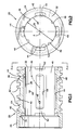
- a finished valve sleeve 20 made according to the method embodying the present invention is illustrated in Figs. 1 and 2.
- the valve sleeve 20 has an outer surface 24 and an inner surface 26.
- the valve sleeve 20 also has a pair of radially extending end surfaces 32, 34.
- the end surfaces 32, 34 extend from the inner surface 26 to the outer surface 24.
- the inner surface 26 has a finished diameter represented by the numeral 39 (see Fig. 2).
- a plurality of annular grooves 42 are formed in the outer surface 24 of the valve sleeve 20.
- the annular grooves 42 allow fluid communication of the valve sleeve 20 with ports in a hydraulic power steering gear housing (not shown), as is known.
- the annular grooves 42 extend circumferentially around the outer surface 24 and are axially spaced along the valve sleeve 20.
- a plurality of annular seal grooves 40 are also formed in the outer surface 24 of the valve sleeve 20 for receiving a seal (not shown) to block fluid leakage between adjacent annular grooves 42.
- a plurality of axially extending grooves 44 are formed in the inner surface 26 of the valve sleeve 20. Adjacent grooves 44 are separated by a respective one of a plurality of axially extending lands 46.
- a plurality of radially extending passages 48 connect the annular grooves 42 with grooves 44 for fluid communication, as is known.
- a pair of seal lands 52 are located at axially opposite end portions of the valve sleeve 20.
- the seal lands 52 extend circumferentially along the inner surface 26 of the valve sleeve 20.
- the axially extending lands 46 and seal lands 52 are arcuate surfaces having the same diameter as the diameter 39 of the inner surface 26.
- the axially extending lands 46 cooperate with axially extending lands on the valve core, as is known. Such cooperation between the lands selectively blocks and allows fluid flow through the grooves 44 of the valve sleeve 20 upon relative rotation between the valve core and valve sleeve.
- the seal lands 52 have a close fit with the outer circumference of the valve core to restrict fluid flow axially outward from the ends of the grooves 44. While only four axially extending grooves 44 and four lands 46 are used in the valve sleeve 20, it should be apparent that a different number of grooves and lands could be used depending on the application of the valve sleeve.
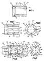
- valve sleeve blank 62 (Fig. 3) is provided.
- the valve sleeve blank 62 is formed from a metal tubular member 64.
- the annular grooves 42, passages 48 and seal grooves 40 are machined in the valve sleeve blank 62.
- the valve sleeve blank 62 is placed in a fixture (not shown), and broached to form the plurality of grooves 44 in the inner surface 26, as illustrated in Figs. 4 and 5. Forming the grooves 44 also defines the locations of the axially extending lands 46. Each of the grooves 44 when initially formed extends axially and completely through the end surfaces 32, 34. Each of the grooves 44 has a base surface 72 and a pair of generally parallel side surfaces 74a, 74b. The base surface 72 of the groove 44 is located between the inner surface 26 and the outer surface 24.
- a pair of first punches 82 (Figs. 6 and 7) is then moved axially into forceful engagement with the end surfaces 32, 34 of the valve sleeve blank 62.
- Each of the pair of first punches 82 has a plurality of projections 84 extending from an end face 86.
- Each of the projections 84 has a planar surface 88 for engaging an end surface 32, 34 of the valve sleeve blank 62.
- the number of projections 84 extending from the end face 86 of each of the first punches 82 corresponds to the number of grooves 44 in the valve sleeve blank 62.
- Four projections 84 are shown extending from the end face 86 of each of the first punches 82.
- the valve sleeve blank 62 is indexed relative to the punch 82 so that each of the projections 84 is axially aligned with a respective groove 44.
- Each of the projections 84 has a width W which is slightly greater than the width of a respective groove 44.
- the width of a groove 44 is defined by the distance between the side surfaces 74a, 74b (Fig. 5) of the groove.
- each of the projections 84 has a width W which permits the projection to engage only material of the end surfaces 32, 34 immediately adjacent and axially aligned with the ends of each of the grooves 44.
- Each of the projections 84 has a planar surface 88 disposed at an angle N (Fig. 6) to the direction of movement of the first punches 82 as they move axially toward a valve sleeve blank 62.
- the angle N is such that the radial outermost portion or leading edge 90 of the planar surface 88 will be the first portion of the projection 84 to engage the end surfaces 32, 34 of the valve sleeve blank 62.
- Each leading edge 90 shears a portion of the material from the valve sleeve blank 62 as the projections 84 are advanced into the end surfaces 32, 34.
- the planar surfaces 88 are angled rearwardly relative to the direction in which the first punches 82 are advanced.
- the material 92 engaged by a projection 84 (Fig. 8) is forced radially inwardly along the planar surface 88 as the first punch 82 advances, until the material is displaced radially inwardly of the inner surface 26.
- the first punches 82 displace material 92 radially inwardly only adjacent each end of the grooves 44.
- the displaced material 92 closes the ends of the grooves 44. Since the first punches 82 displace only the material adjacent the ends of the grooves 44, there is a minimal risk of deforming the valve sleeve blank 62 as compared to the process disclosed in U.S. Patent 4,419,877.
- the valve sleeve 62 is preferably made of a material such as SAE 1144 steel.
- SAE 1144 steel is a machining material, not a cold forming material, and it is relatively brittle, and if it flows too far when cold formed, cracks may form in the material.
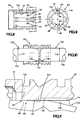
- each of the pair of first punches 82 includes a mandrel 140 (Fig. 6) projecting axially beyond the end face 86 of the punch 82.
- the mandrel 140 moves axially along with the punch 82, when the punch 82 is moved axially to form the lands 52.
- the mandrel 140 is disposed within the valve sleeve 62 and limits the flow of material radially inward.
- Each mandrel 140 includes a shank portion 142 and a generally cylindrical head end portion 144.
- the head end portion 144 includes a rear facing shoulder 150, a cylindrical outer side surface 152, and a front face 154.
- the outer side surface 152 and the front face 154 are joined at a rounded corner surface 156.
- At least the cylindrical outer side surface 152 of the mandrel is preferably hard surfaced with a titanium nitride coating, to give better tool life and to prevent galling or picking up or welding between the mandrel 140 and the material of the valve sleeve blank 26.
- the mandrel 140 is fit axially into the first punch 82.
- a rear portion 161 of the mandrel head end portion 144 is slip fit into a bore 162 in the punch 82.
- the shank portion 142 of the mandrel 140 is press fit into a bore 164 in the punch 82.
- the rear facing shoulder 150 of the mandrel head end portion 144 abuts a forward facing shoulder 160 on the punch 82.
- the head end portion 144 of the mandrel 140 has an outer dimension or diameter 166 which is less than the inside diameter 39 of the valve sleeve 62.
- the outer dimension 166 of the mandrel head end portion 144 is large enough to limit radial inward movement of the material displaced by punch 82.
- the mandrel 140 is a separate piece which is fixed to the first punch 82. It should be understood, however, that the mandrel 140 may be formed integrally with the first punch 82, or that it may be separated from the first punch 82. What is important is that at least a portion of the mandrel 140 be disposed within the valve sleeve 62 when the first punch 82 engages the end surface 34.
- the mandrel 140 is also preferably centered radially with respect to the first punch 82.
- the first punch 82, with the mandrel 140 fixed thereto, is preferably centered radially with respect to the valve sleeve blank 62 when the first punch 82 engages the valve sleeve blank 62. Thus, the material of the blank 62 will be deformed uniformly radially inwardly.
- the material 92 (see Fig. 11) which is displaced from the end surfaces 32, 34 of the valve sleeve blank 62 by the pair of first punches 82, as viewed in Figs. 8, 9 and 11, is made up of three components.
- the three components of the displaced material 92 include material 94 adjacent the base 72 of each groove 44, material 96 adjacent each of the side surfaces 74a, 74b of each groove, and material 98 projecting radially inwardly of the inner surface 26. It can be seen from Fig. 11 that the material 98 has a flattened surface 99 where its radially inward movement has been limited by engagement with the outer side surface 152 of the mandrel 140.
- first punches 82 with the mandrels 140, are then removed from engagement with the end surfaces 32, 34 of the valve sleeve blank 62.
- a pair of second punches 102 (Figs. 10 and 11) act inside the valve sleeve blank 62 to displace the material 98 axially and radially outwardly to form the seal lands 52.
- Each of the second punches 102 has a generally cylindrical body portion 104, of a diameter 112, and an end 106. The cylindrical body portion 104 and end 106 are joined by a tapered frustoconical surface 108.
- the second punches 102 are moved axially towards one another and into the opposite open ends of the valve sleeve blank 62.
- the second punches 102 engage the portions 98 of the displaced material 92 which extend radially inwardly of the inner surface 26.
- the tapered frustoconical surfaces 108 engage the displaced material 98.
- the displaced material 98 indicated by the dashed lines in Fig. 11, is forced along the tapered frustoconical surfaces 108 as the punches 102 axially advance within the valve sleeve blank 62.
- the displaced material 98 is forced radially outwardly by the tapered frustoconical surfaces 108 to form an outer end portion 122 of the seal land 52.
- the tapered frustoconical surfaces 108 also force the displaced material 98 axially into the groove 44 of the valve sleeve blank 62 to form an inner end portion 124 of the seal land 52. This results in providing a relatively long seal land 52, as compared to the prior art process which would machine off the displaced material 98.
- the cylindrical body portions 104 of the second punches 102 each have an outer diameter 112 which is substantially equal to the finished diameter 39 of the inner surface 26 of the finished valve sleeve 20 (Figs. 1 and 2).
- the inner diameter 39 of the valve sleeve blank may then be broached and honed to a final size and finish to provide the finished valve sleeve 20 of Fig. 1.
- One valve sleeve was formed in accordance with the present invention using a mandrel 140 having a head end portion 144 with an outside diameter of 0.694 inches.
- a pair of first punches 82 were used to deform material radially inwardly at 98 (Fig. 11) to a diameter of 0.694 inches.
- a pair of second punches 102 having an outside diameter of 0.720 inches were then used to force the material 98 radially outwardly and axially to a diameter of 0.720 inches.
- the resulting inner surface, including the groove end lands 52, was then machined to form a finished inner surface 26 with a diameter of 0.724 inches.
Landscapes
- Engineering & Computer Science (AREA)
- Mechanical Engineering (AREA)
- Chemical & Material Sciences (AREA)
- Combustion & Propulsion (AREA)
- Transportation (AREA)
- Power Steering Mechanism (AREA)
- Forging (AREA)
- Multiple-Way Valves (AREA)
- Valve Housings (AREA)
Applications Claiming Priority (3)
| Application Number | Priority Date | Filing Date | Title |
|---|---|---|---|
| US07/089,599 US4799303A (en) | 1987-08-26 | 1987-08-26 | Method of making a valve sleeve |
| US214421 | 1988-07-01 | ||
| US07/214,421 US4862571A (en) | 1987-08-26 | 1988-07-01 | Method of making a valve sleeve |
Publications (2)
| Publication Number | Publication Date |
|---|---|
| EP0348798A1 EP0348798A1 (en) | 1990-01-03 |
| EP0348798B1 true EP0348798B1 (en) | 1993-02-03 |
Family
ID=40020142
Family Applications (1)
| Application Number | Title | Priority Date | Filing Date |
|---|---|---|---|
| EP89111211A Expired - Lifetime EP0348798B1 (en) | 1987-08-26 | 1989-06-20 | Method of making a valve sleeve |
Country Status (5)
| Country | Link |
|---|---|
| US (2) | US4799303A (enExample) |
| EP (1) | EP0348798B1 (enExample) |
| JP (1) | JPH0263631A (enExample) |
| DE (1) | DE68904702T2 (enExample) |
| ES (1) | ES2039050T3 (enExample) |
Families Citing this family (13)
| Publication number | Priority date | Publication date | Assignee | Title |
|---|---|---|---|---|
| AU3668689A (en) * | 1988-07-25 | 1990-01-25 | Tokai Trw & Co., Ltd. | A method for manufacturing a single-piece type valve sleeve |
| DE4137994C2 (de) * | 1991-11-19 | 1999-06-02 | Bosch Gmbh Robert | Elektromagnetisch betätigbares Einspritzventil mit einem Düsenträger und Verfahren zur Herstellung eines Düsenträgers eines Einspritzventils |
| JPH06147054A (ja) * | 1992-10-30 | 1994-05-27 | Zexel Corp | プランジャバレルの製造方法 |
| US5522423A (en) * | 1994-08-15 | 1996-06-04 | Elliott; Pat S. | Forged body full port swing check valve |
| DE19814650C2 (de) * | 1998-04-01 | 2002-02-28 | Aeroquip Vickers Internat Gmbh | Verfahren zur Herstellung einer Drosselstelle in einem Schlauch sowie Drosselstelle in einem Schlauch |
| DE19915556A1 (de) * | 1999-04-07 | 2000-10-12 | Zahnradfabrik Friedrichshafen | Verfahren zur Herstellung von Steuernuten in einem Drehschieberventil und nach diesem Verfahren hergestellte Steuerbuchse |
| US6782966B2 (en) | 2001-07-06 | 2004-08-31 | Trw Inc. | Power-assisted steering apparatus with a one-piece, monolithic component |
| DE102008033269B4 (de) * | 2008-07-15 | 2013-05-29 | Zf Friedrichshafen Ag | Rückschlagventil |
| CN102092417A (zh) * | 2010-12-06 | 2011-06-15 | 十堰合骏实业有限公司 | 整体式阀套及其粉末冶金工艺方法 |
| CN105179352A (zh) * | 2015-10-13 | 2015-12-23 | 无锡鹰贝精密轴承有限公司 | 精密阀套 |
| CN109604959B (zh) * | 2018-12-18 | 2021-02-02 | 瑞安市长虹车辆配件有限公司 | 一种转向器阀套内沟槽加工工艺 |
| CN110076529B (zh) * | 2019-05-15 | 2020-12-18 | 山西航天清华装备有限责任公司 | 一种弱刚性径向多孔系精密阀套稳态加工方法 |
| CN112045372B (zh) * | 2020-09-08 | 2022-04-29 | 重庆神箭汽车传动件有限责任公司 | 一种泵体加工方法 |
Family Cites Families (11)
| Publication number | Priority date | Publication date | Assignee | Title |
|---|---|---|---|---|
| US1422655A (en) * | 1920-09-02 | 1922-07-11 | Cleveland Graphite Bronze Co | Bearing and method of making same |
| US1870970A (en) * | 1930-03-07 | 1932-08-09 | Emsco Derrick And Equipment Co | Method of making blind cage sleeves with ball guide integral |
| US2737831A (en) * | 1950-06-02 | 1956-03-13 | American Viscose Corp | Process for making a spinneret |
| US3662462A (en) * | 1970-02-09 | 1972-05-16 | Rohr Corp | Method of securing a bearing race within a bore in a housing |
| US4161873A (en) * | 1978-01-26 | 1979-07-24 | Combustion Engineering, Inc. | Internal and external extruded nipples or nozzles in pipe headers or boiler drums |
| FR2446693A1 (fr) * | 1979-01-16 | 1980-08-14 | Dba | Procede de fabrication d'une douille cylindrique munie de rainures interieures, et outillage pour la mise en oeuvre de ce procede |
| JPS5921441A (ja) * | 1982-07-28 | 1984-02-03 | Toyota Motor Corp | バルブボデ−の製造方法 |
| JPS5992143A (ja) * | 1982-11-15 | 1984-05-28 | Toyota Motor Corp | 内周壁に溝を有する中空部材の製造方法 |
| JPS59185539A (ja) * | 1983-04-06 | 1984-10-22 | Jidosha Kiki Co Ltd | 弁スリ−ブの製造方法 |
| US4543813A (en) * | 1983-09-19 | 1985-10-01 | Trw Cam Gears Limited | Method of making valve sleeves |
| US4614014A (en) * | 1984-10-11 | 1986-09-30 | Buckeye International, Inc. | Method of manufacturing a valve sleeve |
-
1987
- 1987-08-26 US US07/089,599 patent/US4799303A/en not_active Expired - Fee Related
-
1988
- 1988-07-01 US US07/214,421 patent/US4862571A/en not_active Expired - Fee Related
-
1989
- 1989-06-20 EP EP89111211A patent/EP0348798B1/en not_active Expired - Lifetime
- 1989-06-20 ES ES198989111211T patent/ES2039050T3/es not_active Expired - Lifetime
- 1989-06-20 DE DE8989111211T patent/DE68904702T2/de not_active Expired - Fee Related
- 1989-06-30 JP JP1169730A patent/JPH0263631A/ja active Granted
Also Published As
| Publication number | Publication date |
|---|---|
| DE68904702T2 (de) | 1993-05-27 |
| JPH0263631A (ja) | 1990-03-02 |
| US4862571A (en) | 1989-09-05 |
| ES2039050T3 (es) | 1993-08-16 |
| DE68904702D1 (de) | 1993-03-18 |
| EP0348798A1 (en) | 1990-01-03 |
| JPH0371210B2 (enExample) | 1991-11-12 |
| US4799303A (en) | 1989-01-24 |
Similar Documents
| Publication | Publication Date | Title |
|---|---|---|
| EP0348798B1 (en) | Method of making a valve sleeve | |
| EP0605916B1 (en) | A method of manufacturing a torque transmitting housing | |
| US5890287A (en) | Connection structure and process for connecting eye joints and slender metal pipes | |
| US4287749A (en) | Tapered extrusion die and method of forming the same | |
| US4276812A (en) | Power steering valve and method of making the same | |
| GB2236066A (en) | Method and apparatus for tube expansion | |
| US4048703A (en) | Collar sleeves and process and tool for the manufacture thereof | |
| EP0058465B1 (en) | Method of manufacturing universal joint housings | |
| US4419877A (en) | Method of manufacturing a cylindrical sleeve provided with internal grooves, and tool for carrying out this method | |
| EP0348684A1 (en) | Method and apparatus for locating and clamping a workpiece, such as a piston, prior to rotating same in a machining operation | |
| US4688312A (en) | Fuel injection valve having an end flange formed by plastic working and its method of manufacture | |
| US5461776A (en) | Method of manufacturing piston rings | |
| US4768268A (en) | Method for manufacturing a single-piece type valve sleeve | |
| US4543813A (en) | Method of making valve sleeves | |
| JPS59134604A (ja) | 円形状の孔の仕上加工方法及びこの仕上加工方法に使用される工具 | |
| GB2121326A (en) | Valve sleeves | |
| EP0786307B1 (en) | Process for manufacturing a spool valve | |
| US5140881A (en) | Apparatus for manufacturing a cylinder with a connected sleeve | |
| US3730057A (en) | Hydraulic ram assembly | |
| WO2007092775A2 (en) | Self-centering broach | |
| US2358304A (en) | Method of making oil hole twist drills | |
| US5718140A (en) | Method for manufacturing a rotationally symmetrical work-piece of steel | |
| JPH0741351B2 (ja) | 鍛造用パンチ | |
| JPS5992143A (ja) | 内周壁に溝を有する中空部材の製造方法 | |
| EP0352518A2 (en) | Method of manufacturing a single-piece valve sleeve |
Legal Events
| Date | Code | Title | Description |
|---|---|---|---|
| PUAI | Public reference made under article 153(3) epc to a published international application that has entered the european phase |
Free format text: ORIGINAL CODE: 0009012 |
|
| AK | Designated contracting states |
Kind code of ref document: A1 Designated state(s): DE ES FR GB IT |
|
| 17P | Request for examination filed |
Effective date: 19900621 |
|
| 17Q | First examination report despatched |
Effective date: 19910524 |
|
| GRAA | (expected) grant |
Free format text: ORIGINAL CODE: 0009210 |
|
| AK | Designated contracting states |
Kind code of ref document: B1 Designated state(s): DE ES FR GB IT |
|
| REF | Corresponds to: |
Ref document number: 68904702 Country of ref document: DE Date of ref document: 19930318 |
|
| PGFP | Annual fee paid to national office [announced via postgrant information from national office to epo] |
Ref country code: GB Payment date: 19930413 Year of fee payment: 5 |
|
| ITF | It: translation for a ep patent filed | ||
| PGFP | Annual fee paid to national office [announced via postgrant information from national office to epo] |
Ref country code: FR Payment date: 19930507 Year of fee payment: 5 |
|
| ET | Fr: translation filed | ||
| PGFP | Annual fee paid to national office [announced via postgrant information from national office to epo] |
Ref country code: ES Payment date: 19930608 Year of fee payment: 5 |
|
| PGFP | Annual fee paid to national office [announced via postgrant information from national office to epo] |
Ref country code: DE Payment date: 19930628 Year of fee payment: 5 |
|
| REG | Reference to a national code |
Ref country code: ES Ref legal event code: FG2A Ref document number: 2039050 Country of ref document: ES Kind code of ref document: T3 |
|
| PLBE | No opposition filed within time limit |
Free format text: ORIGINAL CODE: 0009261 |
|
| STAA | Information on the status of an ep patent application or granted ep patent |
Free format text: STATUS: NO OPPOSITION FILED WITHIN TIME LIMIT |
|
| 26N | No opposition filed | ||
| PG25 | Lapsed in a contracting state [announced via postgrant information from national office to epo] |
Ref country code: GB Effective date: 19940620 |
|
| PG25 | Lapsed in a contracting state [announced via postgrant information from national office to epo] |
Ref country code: ES Free format text: LAPSE BECAUSE OF THE APPLICANT RENOUNCES Effective date: 19940621 |
|
| GBPC | Gb: european patent ceased through non-payment of renewal fee |
Effective date: 19940620 |
|
| PG25 | Lapsed in a contracting state [announced via postgrant information from national office to epo] |
Ref country code: FR Effective date: 19950228 |
|
| PG25 | Lapsed in a contracting state [announced via postgrant information from national office to epo] |
Ref country code: DE Effective date: 19950301 |
|
| REG | Reference to a national code |
Ref country code: FR Ref legal event code: ST |
|
| REG | Reference to a national code |
Ref country code: ES Ref legal event code: FD2A Effective date: 19991007 |
|
| PG25 | Lapsed in a contracting state [announced via postgrant information from national office to epo] |
Ref country code: IT Free format text: LAPSE BECAUSE OF NON-PAYMENT OF DUE FEES;WARNING: LAPSES OF ITALIAN PATENTS WITH EFFECTIVE DATE BEFORE 2007 MAY HAVE OCCURRED AT ANY TIME BEFORE 2007. THE CORRECT EFFECTIVE DATE MAY BE DIFFERENT FROM THE ONE RECORDED. Effective date: 20050620 |