EP0348769A2 - Dispositif pour presser le matériau d'étanchéité obturant la feute entre deux parties en mouvement relatif, par exemple pour une installation de tambour rotative - Google Patents
Dispositif pour presser le matériau d'étanchéité obturant la feute entre deux parties en mouvement relatif, par exemple pour une installation de tambour rotative Download PDFInfo
- Publication number
- EP0348769A2 EP0348769A2 EP89111042A EP89111042A EP0348769A2 EP 0348769 A2 EP0348769 A2 EP 0348769A2 EP 89111042 A EP89111042 A EP 89111042A EP 89111042 A EP89111042 A EP 89111042A EP 0348769 A2 EP0348769 A2 EP 0348769A2
- Authority
- EP
- European Patent Office
- Prior art keywords
- pressing
- sealing
- sealing material
- mouving
- split
- Prior art date
- Legal status (The legal status is an assumption and is not a legal conclusion. Google has not performed a legal analysis and makes no representation as to the accuracy of the status listed.)
- Withdrawn
Links
Images

Classifications
-
- F—MECHANICAL ENGINEERING; LIGHTING; HEATING; WEAPONS; BLASTING
- F16—ENGINEERING ELEMENTS AND UNITS; GENERAL MEASURES FOR PRODUCING AND MAINTAINING EFFECTIVE FUNCTIONING OF MACHINES OR INSTALLATIONS; THERMAL INSULATION IN GENERAL
- F16J—PISTONS; CYLINDERS; SEALINGS
- F16J15/00—Sealings
- F16J15/16—Sealings between relatively-moving surfaces
- F16J15/34—Sealings between relatively-moving surfaces with slip-ring pressed against a more or less radial face on one member
- F16J15/3436—Pressing means
- F16J15/344—Pressing means the pressing force being applied by means of an elastic ring supporting the slip-ring
-
- F—MECHANICAL ENGINEERING; LIGHTING; HEATING; WEAPONS; BLASTING
- F16—ENGINEERING ELEMENTS AND UNITS; GENERAL MEASURES FOR PRODUCING AND MAINTAINING EFFECTIVE FUNCTIONING OF MACHINES OR INSTALLATIONS; THERMAL INSULATION IN GENERAL
- F16J—PISTONS; CYLINDERS; SEALINGS
- F16J15/00—Sealings
- F16J15/16—Sealings between relatively-moving surfaces
- F16J15/18—Sealings between relatively-moving surfaces with stuffing-boxes for elastic or plastic packings
- F16J15/24—Sealings between relatively-moving surfaces with stuffing-boxes for elastic or plastic packings with radially or tangentially compressed packing
-
- F—MECHANICAL ENGINEERING; LIGHTING; HEATING; WEAPONS; BLASTING
- F16—ENGINEERING ELEMENTS AND UNITS; GENERAL MEASURES FOR PRODUCING AND MAINTAINING EFFECTIVE FUNCTIONING OF MACHINES OR INSTALLATIONS; THERMAL INSULATION IN GENERAL
- F16J—PISTONS; CYLINDERS; SEALINGS
- F16J15/00—Sealings
- F16J15/46—Sealings with packing ring expanded or pressed into place by fluid pressure, e.g. inflatable packings
-
- F—MECHANICAL ENGINEERING; LIGHTING; HEATING; WEAPONS; BLASTING
- F27—FURNACES; KILNS; OVENS; RETORTS
- F27B—FURNACES, KILNS, OVENS OR RETORTS IN GENERAL; OPEN SINTERING OR LIKE APPARATUS
- F27B7/00—Rotary-drum furnaces, i.e. horizontal or slightly inclined
- F27B7/20—Details, accessories or equipment specially adapted for rotary-drum furnaces
- F27B7/22—Rotary drums; Supports therefor
- F27B7/24—Seals between rotary and stationary parts
Definitions
- the invention relates to a device for pressing a sealing material sealing the gap between two parts moving relative to one another - for example in a rotary drum system - consisting of two or more sealing elements inserted into the fixed part, which in the axial direction against a counter surface attached to the rotating part be pressed.
- a preferred application of the above device is the sealing of rotary tubes, for example rotary drum systems.
- the rotary tubes must be sealed against the fixed inlet or outlet constructions, as a pressure deviating from the atmosphere is generally present in the rotary tube, or entry of false air into the rotary tube or gas outlet into the atmosphere must be avoided.
- seals are known and are marketed, for example, by Burgmann, Wolfratshausen.
- the sealing is carried out in such a way that, in the case of two parts which move relative to one another, sealing elements, in particular a packing cord, are inserted into the stationary part, which, by means of a multiplicity of segment-like sheet metal strips and spring elements, against the rotating mating surface connected to the rotary tube - an annular disc - are pressed.
- This object is achieved in that the pressing of the sealing elements is carried out by means of a hose under pressure.
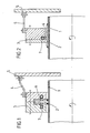
- Figure 1 shows a rotary tube 1, on which the annular counter surface 2 of the sealing structure is welded.
- the packing cord 6 is inserted in the fixed part 3 of the sealing construction, which is connected via a flexible or rigid fastening element 4, depending on the construction of the sealing, to the fixed inlet or outlet construction 5 of the rotary drum system.
- the pressurized tube 7 is also arranged behind the packing cord in the fixed part of the sealing structure, that a pressure force evenly distributed over the entire length of the packing cord presses the packing cord onto the counter surface rotating with the rotary tube.
- the pressure prevailing in the hose is generally generated using a fluid, for example compressed air or water. All inaccuracies of the counter surface, described as a disadvantage, which result in movement of the packing cord, are covered by the hose.
- the contact pressure which decreases due to the wear of the packing cord, can be recognized by the pressure of the fluid present in the tube, and can be corrected by refilling compressed air during operation.
- the constant pressure can be automated by means of a pressure reservoir and appropriate equipment with measuring and control devices. Furthermore, it can be useful to use the fluid for heat exchange by continuously passing it through the hose. Another variation is that the hose can be endless or finite.
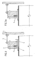
- FIG. 2 shows a construction in which the circular counter surface is replaced by a tube piece 2 which is pushed over the rotary tube and which is welded to the rotary tube to form a unit.
- Figure 3 and 3a shows a construction in which two or more hoses are arranged one behind the other to increase the elasticity.
- a tube as shown in FIG. 3, can be inserted unfilled, in order to be pressurized only when the wasted packing cord requires it, as shown in FIG. 3a.
- the contact pressure can be increased or decreased during operation via the pressure of the fluid, depending on the requirements of the operation. It is also possible to remove the pressure of the fluid completely in certain operating states, for example when starting and stopping or during trial runs of the rotating drum system, in order to protect the packing cord and to reactivate the seal at a certain point in time by releasing pressure.
- a further variation of the embodiment consists in that, for example, part 3 — according to the embodiment in FIG. 1 —is connected to the rotary tube 1, that is to say that packing cord 6 and hose 7 circulate with the rotary tube 1, and the counter surface 2 is designed to be stationary.
Landscapes
- Engineering & Computer Science (AREA)
- General Engineering & Computer Science (AREA)
- Mechanical Engineering (AREA)
- Physics & Mathematics (AREA)
- Architecture (AREA)
- Fluid Mechanics (AREA)
- Sealing Devices (AREA)
- Treatment Of Fiber Materials (AREA)
- Joints Allowing Movement (AREA)
Applications Claiming Priority (2)
| Application Number | Priority Date | Filing Date | Title |
|---|---|---|---|
| DE19883821517 DE3821517A1 (de) | 1988-06-25 | 1988-06-25 | Vorrichtung zum andruecken eines den spalt zwischen zwei relativ zueinander sich bewegenden teilen abdichtenden dichtungsmaterials, beispielsweise bei einer drehtrommelanlage |
| DE3821517 | 1988-06-25 |
Publications (2)
| Publication Number | Publication Date |
|---|---|
| EP0348769A2 true EP0348769A2 (fr) | 1990-01-03 |
| EP0348769A3 EP0348769A3 (fr) | 1991-01-30 |
Family
ID=6357264
Family Applications (1)
| Application Number | Title | Priority Date | Filing Date |
|---|---|---|---|
| EP19890111042 Withdrawn EP0348769A3 (fr) | 1988-06-25 | 1989-06-19 | Dispositif pour presser le matériau d'étanchéité obturant la feute entre deux parties en mouvement relatif, par exemple pour une installation de tambour rotative |
Country Status (2)
| Country | Link |
|---|---|
| EP (1) | EP0348769A3 (fr) |
| DE (1) | DE3821517A1 (fr) |
Cited By (6)
| Publication number | Priority date | Publication date | Assignee | Title |
|---|---|---|---|---|
| EP0510959A1 (fr) * | 1991-04-25 | 1992-10-28 | JAMES HOWDEN & COMPANY LIMITED | Dispositif d'étanchéité |
| US5436780A (en) * | 1991-06-03 | 1995-07-25 | Matsushita Electric Industrial Co., Ltd. | Thin film magnetic head device |
| EP1398549A1 (fr) * | 2002-09-13 | 2004-03-17 | Federal-Mogul Friedberg GmbH | Garniture étanche à anneau glissant |
| LU103007B1 (de) * | 2022-09-16 | 2024-03-18 | Thyssenkrupp Ag | Dichtung für einen Drehrohrofen |
| WO2024056721A1 (fr) * | 2022-09-16 | 2024-03-21 | thyssenkrupp Polysius GmbH | Joint pour four rotatif |
| WO2025061377A1 (fr) * | 2023-09-19 | 2025-03-27 | Eagleburgmann Germany Gmbh & Co. Kg | Système d'étanchéité de four rotatif doté d'un ensemble de protection contre l'usure |
Families Citing this family (2)
| Publication number | Priority date | Publication date | Assignee | Title |
|---|---|---|---|---|
| CH679417A5 (fr) * | 1989-04-25 | 1992-02-14 | Erich Bertsch | |
| DE19959856B4 (de) * | 1999-12-10 | 2006-10-12 | Coperion Waeschle Gmbh & Co. Kg | Zellenradschleuse |
Family Cites Families (2)
| Publication number | Priority date | Publication date | Assignee | Title |
|---|---|---|---|---|
| SE433114B (sv) * | 1980-02-25 | 1984-05-07 | Lkab | Kontakttetning |
| DE8716408U1 (de) * | 1986-12-23 | 1988-04-28 | Feodor Burgmann Dichtungswerke Gmbh & Co, 8190 Wolfratshausen | Dichtung |
-
1988
- 1988-06-25 DE DE19883821517 patent/DE3821517A1/de not_active Withdrawn
-
1989
- 1989-06-19 EP EP19890111042 patent/EP0348769A3/fr not_active Withdrawn
Cited By (7)
| Publication number | Priority date | Publication date | Assignee | Title |
|---|---|---|---|---|
| EP0510959A1 (fr) * | 1991-04-25 | 1992-10-28 | JAMES HOWDEN & COMPANY LIMITED | Dispositif d'étanchéité |
| US5217235A (en) * | 1991-04-25 | 1993-06-08 | James Howden & Co. Ltd. | Seal assembly |
| US5436780A (en) * | 1991-06-03 | 1995-07-25 | Matsushita Electric Industrial Co., Ltd. | Thin film magnetic head device |
| EP1398549A1 (fr) * | 2002-09-13 | 2004-03-17 | Federal-Mogul Friedberg GmbH | Garniture étanche à anneau glissant |
| LU103007B1 (de) * | 2022-09-16 | 2024-03-18 | Thyssenkrupp Ag | Dichtung für einen Drehrohrofen |
| WO2024056721A1 (fr) * | 2022-09-16 | 2024-03-21 | thyssenkrupp Polysius GmbH | Joint pour four rotatif |
| WO2025061377A1 (fr) * | 2023-09-19 | 2025-03-27 | Eagleburgmann Germany Gmbh & Co. Kg | Système d'étanchéité de four rotatif doté d'un ensemble de protection contre l'usure |
Also Published As
| Publication number | Publication date |
|---|---|
| DE3821517A1 (de) | 1989-12-28 |
| EP0348769A3 (fr) | 1991-01-30 |
Similar Documents
| Publication | Publication Date | Title |
|---|---|---|
| DE3405351C2 (de) | Hochdruckdichtung | |
| DE3321819C1 (de) | Hahn mit kugelfoermigem Kueken | |
| EP0348769A2 (fr) | Dispositif pour presser le matériau d'étanchéité obturant la feute entre deux parties en mouvement relatif, par exemple pour une installation de tambour rotative | |
| DE1600650B1 (de) | Ringpackung zum abdichten des spielraumes zwischen zwei axial gegeneinander beweglichen konzentrischen zylinder koerpern | |
| EP0075723B1 (fr) | Dispositif pour amener un fluide sous presssion dans un arbre | |
| DE102010033647A1 (de) | Vorrichtung zum Abdichten einer Stange gegenüber einem Medium und Verfahren zum Abdichten einer Stange gegenüber einem Medium | |
| DE1775552C3 (de) | Lagerung und Walzenzapfendichtung einer sich in einem Flüssigkeitsbehälter drehenden Walze | |
| EP0067239B1 (fr) | Disposition d'échanchéité aux boîtes à labyrinthe pour tiges de piston de cylindres de charge à fluide étant logées hydrostatiquement | |
| EP2730821A1 (fr) | Dispositif et procédé d'isolation étanche d'une pièce de machine par rapport à une deuxième pièce de machine | |
| EP1083994A1 (fr) | Soupape de limitation de debit commandee a precontrainte, en particulier soupape de vaporisation, et barre de vaporisation | |
| DE2121162B2 (de) | Bremsbelagverschleiss-anzeigevorrichtung fuer beidseitig beaufschlagbare scheibenbremsen in einem fahrzeug | |
| CH637571A5 (de) | Mundstueck zur ankoppelung einer elektronenstrahlkanone an einen druckformzylinder zu dessen gravur. | |
| DE2709243C2 (de) | Verfahren und Vorrichtung zum Abdichten einer Welle | |
| DE3819879A1 (de) | Verfahren und anordnung zum anziehen von geflochtenen abdichtungen | |
| CH626694A5 (en) | Shaft seal, in particular for large compressor shafts | |
| DE4223900C2 (de) | Zugwalze | |
| DE4134882A1 (de) | Pumpe fuer fluessiges oder pastoeses foerdergut, wie pharmazeutika, kosmetika, lebensmittel o. dgl. | |
| DE3346220A1 (de) | Reibungskupplung | |
| EP0077461A2 (fr) | Appareil pour enlever une couche membraneuse d'un tambour filtrant rotatif | |
| DE8714654U1 (de) | Einrichtung zur Abdichtung eines Drehrohr- oder Drehherdofens | |
| DE2558651C3 (de) | Wellendichtung mit einem mit der Welle umlaufenden Dichtring | |
| DE2819993C3 (de) | Mundstück zur Ankoppelung einer Elektronenstrahlkanone an Druckformzylinder | |
| DE2950672A1 (de) | Abdichtvorsatz fuer eine sondenbohrung | |
| DE6941771U (de) | Abgedichtetes, durchgehendes rohr fuer einen master-slave-manipulator. | |
| DE2930753C2 (de) | Vorrichtung zum Anpressen und Nachstellen einer Stopfbuchsenpackung |
Legal Events
| Date | Code | Title | Description |
|---|---|---|---|
| PUAI | Public reference made under article 153(3) epc to a published international application that has entered the european phase |
Free format text: ORIGINAL CODE: 0009012 |
|
| AK | Designated contracting states |
Kind code of ref document: A2 Designated state(s): AT BE CH DE FR GB IT LI NL SE |
|
| PUAL | Search report despatched |
Free format text: ORIGINAL CODE: 0009013 |
|
| AK | Designated contracting states |
Kind code of ref document: A3 Designated state(s): AT BE CH DE FR GB IT LI NL SE |
|
| 17P | Request for examination filed |
Effective date: 19901227 |
|
| RHK1 | Main classification (correction) |
Ipc: F16J 15/34 |
|
| 17Q | First examination report despatched |
Effective date: 19921002 |
|
| STAA | Information on the status of an ep patent application or granted ep patent |
Free format text: STATUS: THE APPLICATION HAS BEEN WITHDRAWN |
|
| 18W | Application withdrawn |
Withdrawal date: 19921127 |