EP0348435B1 - Verschlussanordnung für ein fahrzeugteil - Google Patents
Verschlussanordnung für ein fahrzeugteil Download PDFInfo
- Publication number
- EP0348435B1 EP0348435B1 EP88903571A EP88903571A EP0348435B1 EP 0348435 B1 EP0348435 B1 EP 0348435B1 EP 88903571 A EP88903571 A EP 88903571A EP 88903571 A EP88903571 A EP 88903571A EP 0348435 B1 EP0348435 B1 EP 0348435B1
- Authority
- EP
- European Patent Office
- Prior art keywords
- cowl
- lid
- floor
- compartment
- frame
- Prior art date
- Legal status (The legal status is an assumption and is not a legal conclusion. Google has not performed a legal analysis and makes no representation as to the accuracy of the status listed.)
- Expired - Lifetime
Links
- 239000000463 material Substances 0.000 claims abstract description 16
- 230000033001 locomotion Effects 0.000 claims description 15
- 238000000429 assembly Methods 0.000 claims description 8
- 230000000712 assembly Effects 0.000 claims description 8
- 210000000078 claw Anatomy 0.000 description 6
- 238000010276 construction Methods 0.000 description 3
- 229910000831 Steel Inorganic materials 0.000 description 2
- 230000005540 biological transmission Effects 0.000 description 2
- 238000004519 manufacturing process Methods 0.000 description 2
- 239000010959 steel Substances 0.000 description 2
- 239000002826 coolant Substances 0.000 description 1
- 238000001816 cooling Methods 0.000 description 1
- 238000000151 deposition Methods 0.000 description 1
- 239000000428 dust Substances 0.000 description 1
- 239000012530 fluid Substances 0.000 description 1
- 239000010705 motor oil Substances 0.000 description 1
Images


Classifications
-
- B—PERFORMING OPERATIONS; TRANSPORTING
- B60—VEHICLES IN GENERAL
- B60N—SEATS SPECIALLY ADAPTED FOR VEHICLES; VEHICLE PASSENGER ACCOMMODATION NOT OTHERWISE PROVIDED FOR
- B60N2/00—Seats specially adapted for vehicles; Arrangement or mounting of seats in vehicles
- B60N2/24—Seats specially adapted for vehicles; Arrangement or mounting of seats in vehicles for particular purposes or particular vehicles
- B60N2/38—Seats specially adapted for vehicles; Arrangement or mounting of seats in vehicles for particular purposes or particular vehicles specially constructed for use on tractors or like off-road vehicles
-
- B—PERFORMING OPERATIONS; TRANSPORTING
- B62—LAND VEHICLES FOR TRAVELLING OTHERWISE THAN ON RAILS
- B62D—MOTOR VEHICLES; TRAILERS
- B62D25/00—Superstructure or monocoque structure sub-units; Parts or details thereof not otherwise provided for
- B62D25/08—Front or rear portions
- B62D25/10—Bonnets or lids, e.g. for trucks, tractors, busses, work vehicles
Definitions
- This invention relates to a vehicle compartment closure arrangement and more particularly to a vehicle having lid, shroud and a floor members which are each pivotable in selected directions for the purpose of providing access to a component compartment of the vehicle.
- Work vehicles such as, material handling handling vehicles, usually have a cover which is pivotally movable in a single direction (forward or rearward) to uncover a compartment defined by the vehicle frame.
- the cover typically has a plurality of sides and a top surface member which encloses the compartment and isolates the vehicle operator from noise, heat and the like which is generated, for example, by the vehicle engine, battery, hydraulic pumps and motors, filters, and electrical system components and the like housed within the cover and the compartment.
- the sides of the cover are normally long enough in length to extend from the top surface member to the frame of the vehicle when in a compartment covering position. Because of the substantial length of the cover sides, the cover is unable to pivot an adequate distance to totally free the sides of the cover from overlapping at least a portion. of the compartment.
- the amount of pivoting permitted is limited by various portions of the vehicle such as, the counterweight, overhead guard, steering column, and seat mounted on the cover. As a result, access to certain ones of the various components of the vehicle is obstructed making servicing quite difficult and time consuming.
- cowl which is rigidly affixed to the vehicle frame by threaded fasteners and the like.
- the compartment defined by the vehicle frame extends beyond the confines of the hood and to a location beneath a floorboard of the vehicle. Additional vehicle components requiring servicing such as, transmissions, filters and the like are often located within this area of the compartment. In order to gain access to this area the vehicle must be either elevated for service from beneath or the floorboard must be removed and/or moved from covering the compartment. This of course takes additional time and may not provide adequate access to the compartment due to the cowl being located closely adjacent one end of the floor member. Also, portions of the frame which extend between the sides of the vehicle and to which the cowl and floorboard is attached reduces the size of the compartment opening and further limits accessibility.
- the present invention is directed to overcoming one or more of the problems as set forth above.
- a work vehicle having a frame defining a compartment and a floor member releasably connected to the frame and covering a first portion of the compartment.
- a cowl member is pivotally connected to the floor member and pivotally movable in a first direction, from a first position, at which the cowl member is supportably engaged with the frame, to a second position, at which the cowl member is supported on the floor member and spaced from being supportably engaged with the frame.
- the floor member is pivotally movable relative to the cowl member between a first position, at which said floor member covers the first portion of the compartment, and a second position at which the floor member is spaced from covering the first portion of the compartment.
- the floor member is pivotally movable between the first and second positions subsequent to the floor member being released from connection with the frame.
- a supporting member is connected to the frame and a lid member is pivotally connected to the supporting member and pivotally movable in a second direction opposite the first direction, from a first position, at which the lid member covers the second portion of the compartment to a second position, at which the lid member is spaced from covering the compartment second portion.
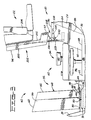
- a work vehicle 10 such as a material handling vehicle of the type capable of picking up, transporting, and depositing a load.
- the work vehicle 10 has a frame 12 and front and rear spaced apart end portions 14,16.
- a steering wheel 18 is rotatively mounted on the vehicle frame 12 at a location on the front end portion 14 of the vehicle and a counterweight 20 is mounted on the vehicle frame 12 at the rear end portion 16 of the vehicle.
- the steering wheel 18 and counterweight 20 are spaced from each other and define an operator station 22 therebetween.
- the frame 12 has first and second spaced apart side portions 24,26 which are each constructed of steel plate to form channel like beams.
- the upper surface portions 27,28 of the first and second side portions 24,26, respectively, serves as a portion of the floor of the operator's station 22, and the inner sides 30 of the first and second spaced apart side portions 24,26 define the width of a compartment 32 located therebetween.
- Various vehicle components 34 such as, the vehicle engine 36, transmission 38, filters 40, and the like are at least partially disposed between the inner sides 30 of the compartment 32.
- the compartment 32 is located between the front and rear end portions 14 and 16 as well as between the inner sides 30 of the first and second side portions 24 and 26.
- a compartment closure arrangement 42 includes a floor member 44 which is constructed of plate steel and has a rectangular configuration.
- the floor member 44 has first and second spaced apart sloped bent end portions 46,48 which engage the upper surface portions 27,28 of the first and second side portions 24,26, respectively, and a first end portion 49.
- the bent end portions 46,48 support the floor member 44 on the upper surface portions 27,28 at a first position 70 of the floor member 44 on the frame 12.
- the first position 70 is a location on the frame 12 at which the floor member 44 covers a first portion 50 of the compartment 32 located between the inner sides 30 and directly beneath the floor member 44.
- a cowl member 52 of the compartment closure arrangement 42, has first and second substantially parallel spaced apart sides 54,56 and a first end portion 58 connected to and between the first and second sides 54,56.
- the first end portion 58 of the cowl member 52 has a rectangular shape and the first and second side members 54,56 of the cowl member 52 each have an end 60 which is angled at an incline toward the front end portion 14 of the vehicle and in a downward direction toward the upper surface portions 27,28 of the frame 12.
- the cowl member 52 is positioned on the vehicle adjacent the floor member 44 and between the floor member 44 and the counterweight 20.
- the first side 54 of the cowl member 52 is supportably engaged with the upper surface portion 27 of the frame first side portion 24 and carried on the upper surface portion 27.
- the second side 56 of the cowl member 52 is supportably engaged with the upper surface portion 28 of the second side portion 26 of the frame 12 and carried on the upper surface portion 28.
- the cowl member 52 partially surrounds various components 34 which are disposed in and extend from the compartment 32 and defines the boundaries of a second portion 62 of the compartment 32.
- a means 64 is provided for pivotally connecting the first end portion 58 of the cowl member 52 to the floor member 44 and for maintaining the cowl member 52 for pivotal movement in a first direction from a first position 66 (Fig. 1), at which the cowl member 52 is supportably engaged with said frame first and second side portions 24,26, as previously discussed, to a second position 68 (Fig. 3), at which the cowl member 52 is supported on the floor member 44 and spaced from being supportably engaged with the upper surface portions 27,28.
- the floor member 44 is pivotally movable about the pivotal connecting means 64 and relative to the cowl member 52 between a first position 70 (Figs.
- the pivotal connecting means 64 preferably includes a first pair of spaced apart hinge assemblies 74 which are fastened in any suitable manner, for example, by threaded fasteners 75, to the first end portion 58 of the cowl member 52 and to the first end portion 49 of the floor member 44. Cutouts 76 are provided in the floor for receiving a portion of each of the hinge assemblies of the first pair 74 in order to maintain the first end portion 58 of the cowl member 52 as close to the floor member 44 as possible. Therefore, the space between the first end portion 58 of the cowl member 52 and the floor member 44 is minimized and the potential for noise, heat, and the like from passing from the compartment 32 and to the operators station 22 is reduced.
- Means 78 is provided for connecting the floor member 44 to the first and second side portions 24,26, of the frame 12 at the first position 70 of the floor member 44, and for releasing the floor member 44 from connection with the first and second frame side portions 24,26, and permitting pivotal movement of the floor member 44 between the first position 70 of the floor member 44, at which said floor member 44 covers the first compartment portion 50, and the second position 72 of the floor member 44, at which the floor member 44 is spaced from covering the first portion 50 of the compartment 32.
- the releasable connecting means 78 preferably includes a plurality of threaded fasteners 80 which are screwthreadably connected to the frame 12 and disposed in apertures 82 in the floor member 44.
- the releasable connecting means 78 is intended to include devices other than those previously described without departing from the spirit of the invention. These devices include locks, clasps, latches and other releasable fasteners which are known in the art.
- a supporting member 84 which is located between the compartment 20 and the cowl member 52, has first and second spaced apart substantially parallel elongated sides 86,88 and a middle portion 90.
- the middle portion 90 is connected to and between the first and second sides 86,88.
- the first and second sides 86,88 are connected to the first and second frame side portions 24,26, respectively, and extend therefrom in an elevationally upward direction and at a preselected angle of inclination toward the counterweight 20.
- the angle of inclination of the first and second sides 86,88 of the supporting member 84 is substantially the same as the angle of inclination of the inclined end 60 of the cowl first and second sides 54,56.
- the first and second sides 86,88 each have a forwardly projecting portion 92 which serves as a stop for the first and second sides 54,56 of the cowl member 52. With the cowl member 52 in the first position 66, the cowl first and second sides 86,88 overlap the forward projecting portions 92 of the cowl first and second sides, respectively. This prevents movement of the first and second sides 86,88 in a direction inwardly relative to the vehicle 10 and towards the compartment 32.
- the compartment closure arrangement 42 includes a lid member 94 having a first and second spaced apart end portions 96,97 first and second spaced apart substantially parallel side portions 98,100, and a top portion 102 upon which an operator's seat 104 is mounted.
- the first end portion 96 of the lid member 94 is connected to the first and second side portions 98,100 of the lid member 94, and the top portion 102 of the lid member 94 is connected to the first end portion 96 and the first and second side portions 98 and 100 of the lid member 94.
- the lid member 92 first and second side portions 98,100 each have an inclined end 106 which is inclined in the same direction and at substantially the same angle as the first and second sides 54,56 of the cowl member 52.
- Means 108 is provided for pivotally connecting the second end portion 97 of the lid member 94 to the middle portion 90 of the supporting member 84 and for maintaining the lid member 94 for pivotal movement in a second direction, opposite the first direction of pivotal movement of the cowl member 52, from a first position 110 (Fig. 1), at which the lid member 94 covers the second portion 62 of the compartment 32, to a second position 112 (Fig. 3), at which the lid member 94 is spaced from covering the compartment 32 and overlies at least a portion of the supporting member 84.
- a gas spring 113 holds the lid member 94 in the second position and allows for selective forceable movement of the lid member 94 between the first and second positions 110,112.
- the lid member 94 is engaged with the cowl member 52 at the first position of the lid and cowl members 94,52.
- the lid member 94 first end portion 96 and first and second side portions 98,100 are engaged with the first end portion 58 and first and second sides 54,56, respectively, of the cowl member 52 at the first position 110, of the lid and cowl members 94,52.
- the weight of the lid member 94 and operators seat 104 is supported on the cowl member 52 at the cowl and lid first positions 66,110.
- the pivotal connecting means 108 of the lid member 94 preferably includes a second pair of spaced apart hinge assemblies 114 which are connected at spaced apart locations to the top portion 102 of the lid member 94 and at spaced apart locations on the middle portion 90 of the supporting member 94.
- Each of the hinge assemblies of the second pair 114 include a first bracket portion 116 connected to the top portion 102 in any suitable manner, such as by fasteners, and a second bracket portion 118 connected to the middle portion 90 in any suitable manner, such as by fasteners.
- the first bracket portion 116 consists of two members which are slidably movable relative to each other and connected together by threaded fasteners 120. This permits the lid member 94 to be adjusted so that it fits squarely on the cowl member 52 and squarely abuts the supporting member 84 at the lid first position 110 of the lid member.
- Means 122 is provided for releasably connecting the first end portion 96 of the lid member 94 to the first end portion 58 of the cowl member 52 and maintaining the lid and cowl members 94,52 at their first positions 66,110 (Fig. 1). Because the cowl and lid members 52,94, pivot in opposite directions to uncover the compartment, the lid member 94, and the weight thereof bearing upon the cowl member 52, will resist inadvertent pivotal movement of the cowl member 52 from the first position 66 towards the second position 68 without the assistance of the latching means 122 in most circumstances.
- the latching means 122 is primarily provided for maintaining the lid member 94 at the first position 110 and from inadvertent movement.
- the latching means 122 provides for selective release of the lid member 94 from connection to the cowl member 52 so that the lid and cowl members 94,52 can be pivoted to their second positions 112,68 for servicing of the components 34 positioned at the second portion 62 of the compartment 32.
- the releasable latching means 122 includes a latching mechanism 124 having a pair of pivotal detented claws 126 which are mounted on the cowl first end portion 58 and a latch pin 128 connected to the lid member 94 at a location adjacent the first end portion 96.
- the claws 126 are selectively movable by a pull cable assembly 130 from a detented closed position to a detented open position.
- the latch pin 128 engages the claws 126 during closure of the lid member 94 and forces the claws 126 from its open position, at which the latch pin 128 is free to move, to its closed position, at which the latch pin is captured by the claws 126. Therefore, movement of the lid member 94 from the second position 112 to the first position will result in the claws 126 being moved to the closed position and the lid 94 being latchably connected to the cowl member 52.
- the counterweight 20 has an annular lip 132 which extends from the counterweight in a direction towards the supporting member 84 and overlaps a portion of the first and second sides 86,88 and middle portion 90 of the supporting member 84.
- a preselected amount of clearance is provided between the supporting member 84 and the lip 132 to allow for manufacturing tolerances and provide a small amount of relative motion between the counterweight 20 and the supporting member 84.
- the overlap between the supporting member 84 and the lip 132 of the counterweight acts as a baffle and reduces the potential for noise and the like from passing from the compartment 32 to the operators station 22.
- the material handling vehicle 10 as shown in Figs. 1 and 2, is in the operational condition and ready to lift, lower, and transport loads between locations within the facility in which it operates.
- the floor, cowl, and lid members 44,52,94 of the compartment closure arrangement 42 are at their first compartment covering positions 70,62, and 110, and noise, heat, dust, and the like within the compartment 32 is blocked from the operators station 22.
- the mechanic determines which of the first and second portions 50,62 of the compartment 32 he wishes to access and simply releases the appropriate ones of the lid cowl and floor members 94,52,44. To completely uncover the second portion 62 of the compartment 32 the mechanic first releases the latching mechanism 124 by pulling the pull cable assembly 132 and pivots the lid member 94 in the second direction, from the first position 110 to the second position 112, and the cowl member 52, in the first direction, from the first position 66 to the second position 68.
- the mechanic releases the floor member 42 from connection with the frame 12 by removing the fasteners 80 and pivots the floor member 44, in the first direction, from the first position 70 of the floor member 44 to the second position 72 of the floor member 44.
- the floor and cowl members 42,52 may be removed as a unit by simply removing the threaded fasteners 80, unlatching the lid member 94 from the cowl member 52, and pivoting the lid member to the second position 112.
- the mechanic may only require that the lid member 94 be raised from the first position 110 to the second position 112. This will afford him access to the upper area of the second portion 62 of the compartment 32. For example, he would be able to check the engine oil level, cooling system coolant level, and battery fluid level with only the lid member 94 in the second position 112.
- means 64 pivotally connects the cowl member 52 directly to the floor 44 and not to the vehicle frame 12 the need for providing structural gussets, connecting flanges, and the like is eliminated.
- This enables the first and second portions 50,62 of the compartment 32 to be open to each other and provides for obstruction free access to the first and second portions 50,62 of the compartment 32.
- the floor member 44 serves as an anchor for the cowl member 52 when fastened to the frame 12 by the releasable connecting means 78 the number of parts required is kept to a minimum and the construction is simplified. Also, since the floor, lid and cowl members 44,94,52 are pivotal the problems associated with fit-up, such as, discussed with respect to individually removable parts has been reduced.
Landscapes
- Engineering & Computer Science (AREA)
- Transportation (AREA)
- Mechanical Engineering (AREA)
- Chemical & Material Sciences (AREA)
- Combustion & Propulsion (AREA)
- Aviation & Aerospace Engineering (AREA)
- Body Structure For Vehicles (AREA)
- Superstructure Of Vehicle (AREA)
Claims (15)
- Ein Arbeitsfahrzeug (10) mit einem Rahmen (12), wobei der Rahmen (12) erste und zweite beabstandete Seitenteile (24, 26) aufweist, die ein Abteil (32) dazwischen definieren, wobei das Arbeitsfahrzeug folgendes aufweist:
ein Bodenglied (44), das mit dem Rahmen (12) lösbar verbunden ist und einen ersten Teil (50) des Abteils (32) abdeckt;
ein Verkleidungs- oder Abdeckglied (52), das schwenkbar mit dem Bodenglied (44) verbunden ist und schwenkbar beweglich ist in einer ersten Richtung aus einer ersten Position (66), in der das Verdeckglied (52) mit dem Rahmen (12) in unterstützendem Eingriff steht und Begrenzungen eines zweiten Teils des Abteils (32) definiert, in eine zweite Position (68), in der das Abdeckglied (52) auf dem Bodenglied (44) getragen wird und von einem unterstützendem Eingriff mit dem Rahmen (12) beabstandet oder entfernt ist, wobei das Bodenglied (44) schwenkbar beweglich ist relativ zu dem Verdeckglied (52) zwischen einer ersten Position (70), in der das Bodenglied (44) den ersten Teil (50) des Abteils (32) abdeckt, und einer zweiten Position (72), in der das Bodenglied (44) vom Abdecken des ersten Teils (50) des Abteils (32) entfernt oder beabstandet ist, wobei das Bodenglied (44) schwenkbar beweglich ist zwischen den ersten und zweiten Positionen,
nachdem das Bodenglied (44) von einer Verbindung mit dem Rahmen (12) gelöst wurde;
ein Tragglied (84), das mit dem Rahmen (12) verbunden ist; und
ein Deckelglied (94), das mit dem Tragglied (84) schwenkbar verbunden ist und schwenkbar beweglich ist in einer zweiten Richtung entgegengesetzt der ersten Richtung, und zwar aus einer ersten Position (110), in der das Deckelglied (94) den zweiten Teil (62) des Abteils (32) abdeckt, in eine zweite Position (112), in der das Deckelglied (94) vom Abdecken des zweiten Teils (62) des Abteils (32) beabstandet oder entfernt ist. - Arbeitsfahrzeug (10) gemäß Anspruch 1, wobei das Deckelglied (94) mit dem Abdeckglied (52) in der ersten Position (110, 66) der Deckel- und Abdeckglieder (94, 52) in Eingriff steht und das Abdeckglied (52) von einer Schwenkbewegung zwischen den ersten und zweiten Positionen (66, 68) des Abdeckglieds abhält.
- Arbeitsfahrzeug (10) gemäß Anspruch 2, wobei die Abdeck- und Deckelglieder (52, 94) jeweils einen ersten Endteil (58, 96) besitzen und Mittel (122) aufweisen zum lösbaren Verriegeln des ersten Endteils (96) des Deckelglieds (94) an dem Abdeckglied (52).
- Arbeitsfahrzeug (10) gemäß Anspruch 1, wobei das Abdeckglied (52) zwischen dem Bodenglied (44) und dem Tragglied (84) angeordnet ist, und zwar in der ersten Position des Abdeckglieds (52), und sich schwenkend zu dem Bodenglied (44) hin bewegt, und zwar während einer Schwenkbewegung des Abdeckglieds (52) in der ersten Richtung.
- Arbeitsfahrzeug (10) gemäß Anspruch 4, wobei die ersten und zweiten Rahmenseitenteile (24, 26) jeweils einen Oberseitenteil (27, 28) umfassen, wobei die Boden- und Deckelglieder (44, 94) jeweils mit mindestens einem der Oberseitenteile (27, 28) der Rahmenseitenteile (24, 26) in Eingriff stehen, und zwar in der ersten Position (70, 110) der Boden- und Deckelglieder (44, 94).
- Arbeitsfahrzeug (10) gemäß Anspruch 5, wobei das Bodenglied (44) einen ersten Endteil (49) besitzt und wobei das Deckelglied einen zweiten Endteil (97) beabstandet von dem ersten Endteil (96) besitzt, wobei die Boden- und Abdeckglieder (44, 52) schwenkbar miteinander verbunden sind an den ersten Endteilen (49, 58) der Boden- und Abdeckglieder, und zwar durch ein erstes Paar von beabstandeten Scharnieranordnungen (74), und wobei der zweite Endteil (97) des Deckels schwenkbar mit dem Tragglied (84) verbunden ist, und zwar durch ein zweites Paar von beabstandeten Scharnieranordnungen (114).
- Arbeitsfahrzeug (10) gemäß Anspruch 1, wobei das Abdeckglied (52) erste und zweite, beabstandete, im wesentlichen parallele Seiten (54, 56) und einen ersten Endteil (58) besitzt, der mit den ersten und zweiten beabstandeten Seiten (54, 56) verbunden ist und sich dazwischen befindet, wobei das Tragglied (84) erste und zweite beabstandete, im wesentlichen parallele Seiten (86, 88) und einen Mittelteil (90) besitzt, der mit den ersten und zweiten Traggliedseiten (86, 88) verbunden ist und sich dazwischen befindet, wobei die erste Seite (54) des Abdeckglieds (52) einen nach vorn vorstehenden Teil (92) der ersten Seite (86) des Tragglieds (84) überlappt, und zwar in der ersten Position (66) des Abdeckglieds (52) und wobei die zweite Seite (56) des Abdeckglieds (52) einen nach vorn ragenden Teil (92) der zweiten Seite (88) des Tragglieds (84) überlappt, und zwar in der ersten Position (66) des Abdeckglieds (52).
- Materialhandhabungsfahrzeug (10), mit einem Rahmen (12) und einer Bedienerstation (22), wobei der Rahmen (12) erste und zweite beabstandete seitenteile (24, 26) besitzt, die ein Abteil (32) dazwischen definieren, und wobei die Bedienerstation (22) ein Deckelglied (94) und einen Bedienersitz (104) besitzt, der auf dem Deckelglied (94) angebracht ist, wobei das Fahrzeug folgendes aufweist: ein Bodenglied (44), das in einer ersten Position (70) angeordnet ist, in der das Bodenglied (44) einen ersten Teil (50) des Abteils (32) abdeckt;
ein Verkleidungs- oder Abdeckglied (52) mit ersten und zweiten beabstandeten Seiten (54, 56) und einem ersten Endteil (58), der mit den ersten und zweiten Seiten (54, 56) verbunden ist und sich dazwischen befindet;
Mittel zum schwenkbaren Verbinden des ersten Endteils (58) des Abdeckglieds mit dem Bodenglied (44) und zum Halten des Abdeckglieds (52) zur Schwenkbewegung in einer ersten Richtung, und zwar aus einer ersten Position (66), in der das Abdeckglied (52) mit den ersten und zweiten Seitenteilen (24, 26) des Rahmens in unterstützendem Eingriff steht, in eine zweite Position (68), in der das Abdeckglied (52) auf dem Bodenglied (44) getragen wird und von einem unterstützendem Eingriff mit dem Rahmen (12) beabstandet oder entfernt ist, wobei das Abdeckglied (52) die Begrenzungen eines zweiten Teils (62) des Abteils (32) definiert;
Mittel (78) zum Verbinden des Bodenglieds (44) mit den ersten und zweiten Seitenteilen (24, 26) des Rahmens, und zwar in der ersten Position (70) des Bodenglieds (44) und zum Lösen des Bodenglieds (44) von der Verbindung mit den ersten und zweiten Seitengliedern (24, 26) und zum Gestatten einer Schwenkbewegung des Bodenglieds (44) zwischen der ersten Position (70) und einer zweiten Position (72), in der das Bodenglied (44) von einem Abdecken des ersten Teils (50) des Abteils (32) beabstandet oder entfernt ist;
ein Tragglied (84) mit ersten und zweiten beabstandeten Seiten (86, 88) und einem Mittelteil (90), der mit den ersten und zweiten Seiten (86, 88) des Tragglieds (84) verbunden ist und sich dazwischen befindet, wobei die ersten und zweiten Seiten (86, 88) des Tragglieds (84) mit den ersten und zweiten Seitenteilen (24, 26) des Rahmens (12) verbunden sind; und
Mittel (108) zum schwenkbaren Verbinden des Deckelglieds (94) mit dem Mittelteil (90) des Tragglieds (84) und zum Halten des Deckelglieds (94) für eine Schwenkbewegung in einer zweiten Richtung entgegengesetzt zu der ersten Richtung, und zwar aus einer ersten Position (110), in der das Deckelglied (94) den zweiten Teil des Abteils (32) abdeckt, in eine zweite Position (112), in der das Deckelglied (94) von einem Abdecken des zweiten Teils (62) des Abteils (32) beabstandet oder entfernt ist. - Materialhandhabungsfahrzeug (10) gemäß Anspruch 8, wobei das Deckelglied (94) auf dem Abdeckglied (52) in der ersten Position (110, 66) der Deckel- und Abdeckglieder (94, 52) getragen ist.
- Materialhandhabungsfahrzeug (10) gemäß Anspruch 9, wobei die Mittel (64) zum schwenkbaren Verbinden des ersten Endteils (58) des Abdeckglieds mit dem Bodenglied (44) ein erstes Paar von Scharnieranordnungen (74) umfaßt, und wobei die Mittel (108) zum schwenkbaren Verbinden des Deckelglieds (94) mit dem Mittelteil (90) des Tragglieds (84) ein zweites Paar von Scharnieranordnungen (114) umfaßt.
- Materialhandhabungsfahrzeug (10) gemäß Anspruch 9, wobei die ersten und zweiten beabstandeten Seiten (54, 56) des Abdeckglieds (52) einen nach vorn ragenden Teil (92) der ersten bzw. zweiten Seiten (86, 88) des Tragglieds (84) überlappen, und zwar in der ersten Position des Abdeckglieds (52).
- Materialhandhabungsfahrzeug (10) gemäß Anspruch 8, wobei die Deckel- und Abdeckglieder (94, 52) zwischen den Boden- und Traggliedern (44, 84) angeordnet sind, und zwar in der ersten Position (110, 66) der Deckel- und Abdeckglieder (94, 52).
- Materialhandhabungsfahrzeug (10) gemäß Anspruch 12, wobei das Deckelglied (94) über mindestens einem Teil des Tragglieds (84) liegt und zwar in der zweiten Position (112) des Deckelglieds (94), und wobei das Abdeckglied (52) über mindestens einem Teil des Bodenglieds (44) liegt, und zwar in der zweiten Position (68) des Abdeckglieds (52).
- Materialhandhabungsfahrzeug (10) gemäß Anspruch 8, wobei die Mittel (78) zum Verbinden des Bodenglieds (44) mit den ersten und zweiten Seiten (24, 26) des Rahmens eine Vielzahl von Gewindebefestigungsmitteln (80) umfaßt, die schraubgewindemäßig mit dem Rahmen (12) verbunden sind und in Öffnungen (82) in dem Bodenglied (44) angeordnet sind.
- Materialhandhabungsfahrzeug (10) gemäß Anspruch 9, wobei das Deckelglied (94) einen ersten Endteil (96) besitzt und Mittel (122) umfaßt zum lösbaren Verbinden des ersten Endteils (96) des Deckelglieds (94) mit dem ersten Endteil (58) des Abdeckglieds (52), und zwar in der ersten Position (66, 110) der Deckel- und Abdeckglieder (94, 52).
Applications Claiming Priority (2)
| Application Number | Priority Date | Filing Date | Title |
|---|---|---|---|
| US07/134,420 US4785900A (en) | 1987-12-17 | 1987-12-17 | Vehicle compartment closure arrangement |
| US134420 | 1987-12-17 |
Publications (3)
| Publication Number | Publication Date |
|---|---|
| EP0348435A1 EP0348435A1 (de) | 1990-01-03 |
| EP0348435A4 EP0348435A4 (en) | 1991-06-19 |
| EP0348435B1 true EP0348435B1 (de) | 1993-11-03 |
Family
ID=22463314
Family Applications (1)
| Application Number | Title | Priority Date | Filing Date |
|---|---|---|---|
| EP88903571A Expired - Lifetime EP0348435B1 (de) | 1987-12-17 | 1988-03-21 | Verschlussanordnung für ein fahrzeugteil |
Country Status (6)
| Country | Link |
|---|---|
| US (1) | US4785900A (de) |
| EP (1) | EP0348435B1 (de) |
| JP (1) | JPH02502529A (de) |
| CA (1) | CA1288455C (de) |
| DE (1) | DE3885454D1 (de) |
| WO (1) | WO1989005750A1 (de) |
Families Citing this family (17)
| Publication number | Priority date | Publication date | Assignee | Title |
|---|---|---|---|---|
| US5228531A (en) * | 1991-06-14 | 1993-07-20 | Deere & Company | Battery hold-down mechanism |
| JP2645792B2 (ja) * | 1993-03-31 | 1997-08-25 | 池田物産株式会社 | 産業車両の座席装置 |
| DE69829343T2 (de) * | 1997-10-02 | 2006-04-13 | Kanzaki Kokyukoki Mfg. Co., Ltd., Amagasaki | Befestigungsvorrichtung eines Fahrzeugpaneels |
| US6371232B1 (en) | 1999-04-30 | 2002-04-16 | Franklin Equipment Co., Inc. | Tractor cab providing under-cab component access |
| JP2001180519A (ja) | 1999-12-28 | 2001-07-03 | Kawasaki Heavy Ind Ltd | 作業用四輪車 |
| US6460916B2 (en) * | 2000-01-07 | 2002-10-08 | Kawasaki Jukogyo Kabushiki Kaisha | Utility vehicle |
| FR2836112B1 (fr) * | 2002-02-19 | 2004-04-23 | Gruau Laval | Cabine approfondie dans un vehicule utilitaire |
| JP4085675B2 (ja) | 2002-04-01 | 2008-05-14 | 株式会社豊田自動織機 | 産業車両 |
| KR20040083415A (ko) * | 2002-10-18 | 2004-10-01 | 신갸타피라 미쓰비시 가부시키가이샤 | 좌석 및 이를 구비한 작업기계 |
| JP3809954B2 (ja) * | 2002-10-23 | 2006-08-16 | 株式会社小松製作所 | チルトフロアを備えた作業車両 |
| JP4184858B2 (ja) * | 2003-04-10 | 2008-11-19 | 株式会社小松製作所 | 作業機械の運転室 |
| US7216734B2 (en) * | 2003-09-25 | 2007-05-15 | Kobelco Construction Machinery Co., Ltd. | Construction machine |
| CN101443257A (zh) * | 2006-05-12 | 2009-05-27 | 克朗设备公司 | 用于材料搬运车辆的座椅甲板组件或车厢罩 |
| EP2281733B1 (de) * | 2009-08-05 | 2016-01-06 | CLAAS Tractor S.A.S. | Landwirtschaftliches Fahrzeug mit einer Kabine mit doppelwandiger Bodenanordnung |
| US8316977B2 (en) * | 2010-12-22 | 2012-11-27 | Kawasaki Jukogyo Kabushiki Kaisha | Utility vehicle |
| US8499882B2 (en) * | 2010-12-28 | 2013-08-06 | Kawasaki Jukogyo Kabushiki Kaisha | Utility vehicle |
| JP7748380B2 (ja) | 2020-03-06 | 2025-10-02 | オシュコッシュ・コーポレーション | リフトデバイスの革新 |
Citations (8)
| Publication number | Priority date | Publication date | Assignee | Title |
|---|---|---|---|---|
| US1040501A (en) * | 1905-10-25 | 1912-10-08 | Abraham T H Brower | Printing-press. |
| US4120375A (en) * | 1976-04-15 | 1978-10-17 | Kabushiki Kaisha Toyoda Jidoshokki Seisakusho | Tiltable cab construction for an industrial vehicle |
| US4238008A (en) * | 1978-10-06 | 1980-12-09 | Towmotor Corporation | Control valve linkage |
| US4312418A (en) * | 1980-03-31 | 1982-01-26 | Clark Equipment Company | Pivoted valve and hood for lift truck |
| US4355695A (en) * | 1980-10-20 | 1982-10-26 | Towmotor Corporation | Article restraining device |
| US4359121A (en) * | 1980-11-24 | 1982-11-16 | Clark Equipment Company | Lift truck hood mechanism and method for operation thereof |
| US4362220A (en) * | 1979-06-02 | 1982-12-07 | Coventry Climax Limited | Industrial truck |
| US4506750A (en) * | 1983-07-18 | 1985-03-26 | Towmotor Corporation | Pivotal hood arrangement |
Family Cites Families (3)
| Publication number | Priority date | Publication date | Assignee | Title |
|---|---|---|---|---|
| US4040501A (en) * | 1976-04-26 | 1977-08-09 | Haswell John W | Lift truck |
| US4397916A (en) * | 1980-02-29 | 1983-08-09 | Mitsui Petrochemical Industries, Ltd. | Laminated multilayer structure |
| US4770263A (en) * | 1985-12-25 | 1988-09-13 | Nissan Motor Co., Ltd. | Body constuction of industrial vehicle |
-
1987
- 1987-12-17 US US07/134,420 patent/US4785900A/en not_active Expired - Fee Related
-
1988
- 1988-03-21 WO PCT/US1988/000855 patent/WO1989005750A1/en not_active Ceased
- 1988-03-21 EP EP88903571A patent/EP0348435B1/de not_active Expired - Lifetime
- 1988-03-21 DE DE88903571T patent/DE3885454D1/de not_active Expired - Lifetime
- 1988-03-21 JP JP63503208A patent/JPH02502529A/ja active Pending
- 1988-11-23 CA CA000583960A patent/CA1288455C/en not_active Expired - Lifetime
Patent Citations (8)
| Publication number | Priority date | Publication date | Assignee | Title |
|---|---|---|---|---|
| US1040501A (en) * | 1905-10-25 | 1912-10-08 | Abraham T H Brower | Printing-press. |
| US4120375A (en) * | 1976-04-15 | 1978-10-17 | Kabushiki Kaisha Toyoda Jidoshokki Seisakusho | Tiltable cab construction for an industrial vehicle |
| US4238008A (en) * | 1978-10-06 | 1980-12-09 | Towmotor Corporation | Control valve linkage |
| US4362220A (en) * | 1979-06-02 | 1982-12-07 | Coventry Climax Limited | Industrial truck |
| US4312418A (en) * | 1980-03-31 | 1982-01-26 | Clark Equipment Company | Pivoted valve and hood for lift truck |
| US4355695A (en) * | 1980-10-20 | 1982-10-26 | Towmotor Corporation | Article restraining device |
| US4359121A (en) * | 1980-11-24 | 1982-11-16 | Clark Equipment Company | Lift truck hood mechanism and method for operation thereof |
| US4506750A (en) * | 1983-07-18 | 1985-03-26 | Towmotor Corporation | Pivotal hood arrangement |
Also Published As
| Publication number | Publication date |
|---|---|
| EP0348435A1 (de) | 1990-01-03 |
| EP0348435A4 (en) | 1991-06-19 |
| JPH02502529A (ja) | 1990-08-16 |
| CA1288455C (en) | 1991-09-03 |
| DE3885454D1 (de) | 1993-12-09 |
| US4785900A (en) | 1988-11-22 |
| WO1989005750A1 (en) | 1989-06-29 |
Similar Documents
| Publication | Publication Date | Title |
|---|---|---|
| EP0348435B1 (de) | Verschlussanordnung für ein fahrzeugteil | |
| US4312418A (en) | Pivoted valve and hood for lift truck | |
| US7320380B2 (en) | Swiveling utility machine having swivel deck | |
| US7481289B2 (en) | Swiveling work machine | |
| US4506750A (en) | Pivotal hood arrangement | |
| EP2765242A1 (de) | Baumaschine | |
| CA1071992A (en) | Operator's seat assembly | |
| EP0792787A2 (de) | Motorhaube | |
| EP1462579A1 (de) | Gegengewicht für Hydraulikbagger | |
| US4040501A (en) | Lift truck | |
| KR960000112B1 (ko) | 리프트 트럭 및 그 제조방법 | |
| US4238008A (en) | Control valve linkage | |
| US6688328B2 (en) | Valve and tank enclosure assembly | |
| CA3160089A1 (en) | Stowing device, cab, and working machine | |
| US4889203A (en) | Composite engine enclosure | |
| EP1462578B1 (de) | Baumaschine | |
| JP3280285B2 (ja) | 農作業機の運転部構造 | |
| EP2554753B1 (de) | Kleiner Bagger | |
| US6290286B1 (en) | Construction machine | |
| US10273653B1 (en) | Component sliding mechanism in work vehicle | |
| US20020060101A1 (en) | Control handle pivot apparatus | |
| EP1177124B1 (de) | Schlepperkabine mit unterbodenzugangsklappe | |
| JPH02197408A (ja) | トーイングトラクタのドローバー | |
| JPH08199627A (ja) | コントロールボックスの開閉装置 | |
| JP3132617B2 (ja) | 産業車両のシート取付け装置 |
Legal Events
| Date | Code | Title | Description |
|---|---|---|---|
| PUAI | Public reference made under article 153(3) epc to a published international application that has entered the european phase |
Free format text: ORIGINAL CODE: 0009012 |
|
| 17P | Request for examination filed |
Effective date: 19890629 |
|
| AK | Designated contracting states |
Kind code of ref document: A1 Designated state(s): DE FR GB |
|
| RIN1 | Information on inventor provided before grant (corrected) |
Inventor name: NASKY, DANIEL, J. |
|
| A4 | Supplementary search report drawn up and despatched |
Effective date: 19910502 |
|
| AK | Designated contracting states |
Kind code of ref document: A4 Designated state(s): DE FR GB |
|
| 17Q | First examination report despatched |
Effective date: 19930222 |
|
| GRAA | (expected) grant |
Free format text: ORIGINAL CODE: 0009210 |
|
| AK | Designated contracting states |
Kind code of ref document: B1 Designated state(s): DE FR GB |
|
| PG25 | Lapsed in a contracting state [announced via postgrant information from national office to epo] |
Ref country code: DE Effective date: 19931103 |
|
| REF | Corresponds to: |
Ref document number: 3885454 Country of ref document: DE Date of ref document: 19931209 |
|
| ET | Fr: translation filed | ||
| PG25 | Lapsed in a contracting state [announced via postgrant information from national office to epo] |
Ref country code: GB Effective date: 19940321 |
|
| PLBE | No opposition filed within time limit |
Free format text: ORIGINAL CODE: 0009261 |
|
| STAA | Information on the status of an ep patent application or granted ep patent |
Free format text: STATUS: NO OPPOSITION FILED WITHIN TIME LIMIT |
|
| 26N | No opposition filed | ||
| GBPC | Gb: european patent ceased through non-payment of renewal fee |
Effective date: 19940321 |
|
| PG25 | Lapsed in a contracting state [announced via postgrant information from national office to epo] |
Ref country code: FR Effective date: 19941130 |
|
| REG | Reference to a national code |
Ref country code: FR Ref legal event code: ST |