EP0348319A1 - Türverriegelung und Türentriegelung für Herde mit pyrolytischer Selbstreinigung - Google Patents
Türverriegelung und Türentriegelung für Herde mit pyrolytischer Selbstreinigung Download PDFInfo
- Publication number
- EP0348319A1 EP0348319A1 EP19890440057 EP89440057A EP0348319A1 EP 0348319 A1 EP0348319 A1 EP 0348319A1 EP 19890440057 EP19890440057 EP 19890440057 EP 89440057 A EP89440057 A EP 89440057A EP 0348319 A1 EP0348319 A1 EP 0348319A1
- Authority
- EP
- European Patent Office
- Prior art keywords
- latch
- cooking chamber
- door locking
- unlocking device
- lock
- Prior art date
- Legal status (The legal status is an assumption and is not a legal conclusion. Google has not performed a legal analysis and makes no representation as to the accuracy of the status listed.)
- Granted
Links
- 238000010411 cooking Methods 0.000 title claims abstract description 23
- 230000005540 biological transmission Effects 0.000 claims abstract description 6
- 230000001360 synchronised effect Effects 0.000 claims abstract description 5
- 238000004140 cleaning Methods 0.000 claims description 11
- 239000002184 metal Substances 0.000 claims description 3
- 238000000197 pyrolysis Methods 0.000 abstract description 10
- 238000006073 displacement reaction Methods 0.000 description 2
- 210000002105 tongue Anatomy 0.000 description 2
- 239000000470 constituent Substances 0.000 description 1
- 238000010276 construction Methods 0.000 description 1
- 238000010438 heat treatment Methods 0.000 description 1
- 230000007257 malfunction Effects 0.000 description 1
- 230000001131 transforming effect Effects 0.000 description 1
Images
Classifications
-
- F—MECHANICAL ENGINEERING; LIGHTING; HEATING; WEAPONS; BLASTING
- F24—HEATING; RANGES; VENTILATING
- F24C—DOMESTIC STOVES OR RANGES ; DETAILS OF DOMESTIC STOVES OR RANGES, OF GENERAL APPLICATION
- F24C15/00—Details
- F24C15/02—Doors specially adapted for stoves or ranges
- F24C15/022—Latches
Definitions
- the invention relates to a device for locking and unlocking a door for a cooking chamber, in particular for a cooking chamber with pyrolysis cleaning.
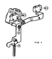
- latches controlled by electromagnet as in documents FR 73 13 831 and FR 73 01 363; devices with locking arms driven by an electric motor and controlled by micro-contacts such as, for example, the one shown in FIG. 1 and which is used by the applicant for its manufacturer reference ovens 800.
- This device consists of a motor (M), two micro-contacts (MC1) and (MC2), a lever (L), a latch (V), a spring (R).
- the motor (M) starts and drives the lever (L) in rotation to release the lock (V) which, under the action of the spring (R ), go down and lock the door.
- the bolt (V) going down releases the micro-contact (MC1) allowing the heating to start up for the cleaning cycle, and in its rotation, the lever (L) presses on the micro-contact (MC2) stopping thus the motor supply.
- the motor By placing the main switch in a position other than pyrolysis, the motor is again supplied with power, but then turns in the opposite direction.
- the engine can only be powered if the pyrolysis thermostat has switched, i.e. the temperature in the enclosure is lower than the temperature required by the regulations in force.
- This device therefore has two moving parts, the lever (L) and the latch (V), each of them controlling a micro-contact, and requiring two non-integral guide means.
- the major drawbacks of the device are that they require significant construction play, further amplified by the length of the lever (L), acting on the micro-contacts by two separate moving parts, and actuating the micro-contact (MC2). and the latch (V) by two separate arms of the lever (L) thus separating the two controls.
- These clearances are, in a certain number of cases, the cause of malfunctions, for example a total locking of the door or an unlocking at the end of pyrolysis followed immediately by a new locking.
- the applicant has imposed itself to control the two micro-contacts by means of a single finger secured to the lock, and to combine all of the guidance and positioning functions on a single support, in order to reduce Games.
- the device for locking and unlocking the door for a cooking chamber comprises a synchronous motor, a movable lock carrying a latch, a return spring, two micro-contacts and is characterized in that it further comprises on the one hand a single support carrying the synchronous motor and the latch, and at least one means for lateral guidance of said latch secured to the support, on the other hand a single transmission arm secured by one of its ends to the axis of the motor synchronous and comprising at its at the other end, an attachment means for the return spring, and a latch drive element capable of producing a rectilinear vertical displacement of the latch, for example a cam.
- the lock has a single finger intended to actuate in turn the tongues of two micro-contacts, placed in the same plane. If the associated electrical circuit requires more than two micro-contacts, a plurality of fingers can be provided if necessary.
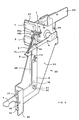
- the preferred nonlimiting embodiment shown in the attached figures mainly consists of: - two micro-contacts (1, 2), - a spring (3), - a transmission arm (4), - a movable lock (5), - a latch (6) integral with the lock (5), - a reduction motor (7), - a bar (8), - a support (20).
- the support (20) is designed both to support all of the elements constituting the locking-unlocking device, and to perform all of the guiding functions of all the moving parts of the same device.
- the support (20) is formed from a cut and folded sheet metal plate.
- a vertical central plate (26) carrying a stamped (28) said central plate extends partly high by a horizontal upper tab (21) and a vertical border (22) obtained by folding, on the other hand also in the upper part, of a lateral tab (27) vertical and perpendicular to the central plate (26) and on the other hand in the lower part, with a lower leg (24) vertical and perpendicular to the central plate (26), and with a vertical border (23) parallel to the central plate (26), the leg (24) and the border (23) being obtained by folding, the tab (24) comprising a latch guide means (6), for example a light (25), vertical, rectangular, having guide throttles (32) adjusted to the thickness of the latch for example and not limited to the number of two, arranged opposite one another.
- a latch guide means (6) for example a light (25), vertical, rectangular, having guide throttles (32) adjusted to the thickness of the latch for example and not limited to the number of two, arranged opposite one another
- the main functions of the various parts of the support (20) which have just been listed are not limited to: fixing and positioning of the entire device on the frame of the cooking enclosure by any suitable means, for example as in the figures by screwing or riveting the edges (22), (23) on the uprights (9a), (9b) of the frame (9).
- - micro-contact support (1) and (2) so that the open and closed positions of the control tabs are in the same vertical plane parallel to the direction of movement of the latch.
- - motor support (7) which is fixed by any appropriate means (29) in the upper part of the central plate (26), preferably, due to the size of the other side of said plate (26) relative to the arm (4) and lock (5).
- the support also has other functions described below.
- the lock is a flat metal rod substantially L-shaped and having at its lower end a latch (6) guided vertically and laterally by the light (25) and the throttles (32), at its upper end two fasteners ( 10a, 10b) and a side finger (11) obtained by cutting and folding.
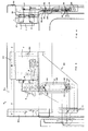
- the transmission arm (4) is integral at one of its ends with the motor shaft (7) and has at the other of its ends a hooking means (4a) for the spring (3), and in look of the lock a cam (4b) capable of transforming the circular movement of the arm (4) into a rectilinear movement of the lock (5) (see FIG. 2).
- the spring is a standard spring attached on the one hand to (4a), and on the other to one or other of the fasteners (10a, 10b) of the lock (5) according to the chosen tension. It is possible to provide a higher number of fasteners.
- the support (20) is completed by a bar (8) ensuring with the central plate (26) of the support the lateral guides of the latch (5), respectively lateral guide on the enclosure side, and lateral on the outside side.
- the bar is made integral with the support (20) by two sockets (30) locked by screws (31) or by any other suitable means.
- the sockets (30) constitute fixed points of the assembly (support (20), bar (8)) which cooperate with the oblong slots (13) provided in the latch (5) to allow its displacement.
- the slots (13) extend parallel to the axis of movement of the lock (5) and their length is appropriate to the amplitude of the sliding of said lock.
- the device works as follows:
- the motor (7) starts and drives the arm (4), and under the action of the spring the latch (5) passes in the low position as indicated by dotted lines in FIG. 3.
- the latch (6) descends and locks the door, then the finger (11) presses on the tab of the micro-contact (2) which cuts the power supply to the motor (7) .
- microswitch tab (1) has been released and the cleaning cycle begins.
- the motor is again supplied with power (if the enclosure temperature is lower than the temperature required by regulations. tations), but turns in the opposite direction to the previous case.
- the lever (4) and the cam (4b) the latch (5) goes to the high position and releases the door, then the finger (11) presses on the microswitch tongue (1 ) to cut off the power to the motor.
- the lock (5) controls the two micro-contacts by means of a single finger (11), the movement of said lock being controlled by the single lever (4) completed by the spring (3) .
- the invention is not limited to the embodiment shown and described above but covers all the variants, in particular the variants of shapes and dimensions of the constituent parts.
Landscapes
- Engineering & Computer Science (AREA)
- Chemical & Material Sciences (AREA)
- Combustion & Propulsion (AREA)
- Mechanical Engineering (AREA)
- General Engineering & Computer Science (AREA)
- Electric Ovens (AREA)
- Cookers (AREA)
Applications Claiming Priority (2)
| Application Number | Priority Date | Filing Date | Title |
|---|---|---|---|
| FR8808417A FR2633033B1 (fr) | 1988-06-20 | 1988-06-20 | Dispositif de verrouillage et deverrouillage de porte pour enceinte de cuisson a nettoyage par pyrolyse |
| FR8808417 | 1988-06-20 |
Publications (2)
| Publication Number | Publication Date |
|---|---|
| EP0348319A1 true EP0348319A1 (de) | 1989-12-27 |
| EP0348319B1 EP0348319B1 (de) | 1991-10-30 |
Family
ID=9367612
Family Applications (1)
| Application Number | Title | Priority Date | Filing Date |
|---|---|---|---|
| EP19890440057 Expired - Lifetime EP0348319B1 (de) | 1988-06-20 | 1989-06-20 | Türverriegelung und Türentriegelung für Herde mit pyrolytischer Selbstreinigung |
Country Status (3)
| Country | Link |
|---|---|
| EP (1) | EP0348319B1 (de) |
| DE (1) | DE68900377D1 (de) |
| FR (1) | FR2633033B1 (de) |
Cited By (3)
| Publication number | Priority date | Publication date | Assignee | Title |
|---|---|---|---|---|
| US6709029B2 (en) | 2001-12-21 | 2004-03-23 | Emerson Electric Co. | Door latch mechanism and associated components for a self-cleaning oven |
| US6863316B2 (en) * | 2001-12-21 | 2005-03-08 | Emerson Electric Co. | Door latch mechanism and associated components for a self-cleaning oven |
| WO2007137965A1 (de) * | 2006-06-01 | 2007-12-06 | BSH Bosch und Siemens Hausgeräte GmbH | Verriegelungsvorrichtung zum verriegeln einer gargerätetür |
Citations (3)
| Publication number | Priority date | Publication date | Assignee | Title |
|---|---|---|---|---|
| US3462584A (en) * | 1967-08-09 | 1969-08-19 | Kelvinator Inc | Range oven door latching device |
| US3757084A (en) * | 1971-09-27 | 1973-09-04 | Corning Glass Works | Door latching system |
| US4593945A (en) * | 1984-03-14 | 1986-06-10 | The Stanley Works | Oven latch assembly |
-
1988
- 1988-06-20 FR FR8808417A patent/FR2633033B1/fr not_active Expired - Fee Related
-
1989
- 1989-06-20 DE DE8989440057T patent/DE68900377D1/de not_active Expired - Fee Related
- 1989-06-20 EP EP19890440057 patent/EP0348319B1/de not_active Expired - Lifetime
Patent Citations (3)
| Publication number | Priority date | Publication date | Assignee | Title |
|---|---|---|---|---|
| US3462584A (en) * | 1967-08-09 | 1969-08-19 | Kelvinator Inc | Range oven door latching device |
| US3757084A (en) * | 1971-09-27 | 1973-09-04 | Corning Glass Works | Door latching system |
| US4593945A (en) * | 1984-03-14 | 1986-06-10 | The Stanley Works | Oven latch assembly |
Cited By (4)
| Publication number | Priority date | Publication date | Assignee | Title |
|---|---|---|---|---|
| US6709029B2 (en) | 2001-12-21 | 2004-03-23 | Emerson Electric Co. | Door latch mechanism and associated components for a self-cleaning oven |
| US6863316B2 (en) * | 2001-12-21 | 2005-03-08 | Emerson Electric Co. | Door latch mechanism and associated components for a self-cleaning oven |
| WO2007137965A1 (de) * | 2006-06-01 | 2007-12-06 | BSH Bosch und Siemens Hausgeräte GmbH | Verriegelungsvorrichtung zum verriegeln einer gargerätetür |
| US8714148B2 (en) | 2006-06-01 | 2014-05-06 | Bsh Bosch Und Siemens Haugeraete Gmbh | Locking apparatus for locking a cooking device door |
Also Published As
| Publication number | Publication date |
|---|---|
| FR2633033B1 (fr) | 1990-09-28 |
| DE68900377D1 (de) | 1991-12-05 |
| FR2633033A1 (fr) | 1989-12-22 |
| EP0348319B1 (de) | 1991-10-30 |
Similar Documents
| Publication | Publication Date | Title |
|---|---|---|
| GB2143579A (en) | Releasable hold-open device for a door closer | |
| EP0959206A1 (de) | Kraftfahrzeugtürschloss mit elektrischer Verriegelung | |
| JPS60112977A (ja) | 可動部片の作動装置 | |
| EP0348319B1 (de) | Türverriegelung und Türentriegelung für Herde mit pyrolytischer Selbstreinigung | |
| US6380520B1 (en) | Toaster with improved safety device | |
| EP0159238A1 (de) | Elektromechanishe Schlossbedienung und Kraftfahrzeugtürschloss damit versehen | |
| EP0860132B1 (de) | Brotröster mit Mehrstellungsaufnahmefach | |
| CA2007196A1 (fr) | Contacteur-inverseur protege utilisant un systeme de transmission multifonctionnel pour la commande d'interrupteurs de confirmation | |
| JP2003343853A (ja) | グリル | |
| FR2490707A1 (fr) | Serrure a pene dormant et pene demi-tour | |
| FR2695426A1 (fr) | Serrure à commande électrique à distance, destinée à équiper une porte. | |
| JP4118987B2 (ja) | 扉用錠止装置 | |
| BE1001398A6 (fr) | Serrure a dispositif d'embrayage et de debrayage. | |
| EP0247914B1 (de) | Manuelle Sperr- und Lösevorrichtung eines Verriegelungs- und motorischen Betätigungssystems für Kipptore | |
| FR2651268A2 (fr) | Verrou automatique de blocage par electro-aimant de la tringle coulissante d'un serrure multi-penes. | |
| CN108493067B (zh) | 断路器系统及手车式断路器 | |
| FR2864208A1 (fr) | Four electromenager avec support coulissant pour les aliments | |
| EP1029491B1 (de) | Sicherheits- und/oder Kontrollvorrichtung für elektrische Kochgeräte | |
| US2951436A (en) | Toaster structure | |
| FR2697278A1 (fr) | Dispositif de verrouillage/déverrouillage pour portail à deux battants, et portail équipé d'un tel dispositif. | |
| FR2657458A1 (fr) | Commutateur electrique bistable, notamment pour la commande de l'eclairage d'un vehicule automobile. | |
| JPH0222565Y2 (de) | ||
| JP2873512B2 (ja) | 展示ケース等における引戸装置 | |
| FR2541352A1 (fr) | Dispositif perfectionne de commande de portes | |
| EP0338315A2 (de) | Mikrowellenofen |
Legal Events
| Date | Code | Title | Description |
|---|---|---|---|
| PUAI | Public reference made under article 153(3) epc to a published international application that has entered the european phase |
Free format text: ORIGINAL CODE: 0009012 |
|
| AK | Designated contracting states |
Kind code of ref document: A1 Designated state(s): DE GB |
|
| 17P | Request for examination filed |
Effective date: 19891216 |
|
| 17Q | First examination report despatched |
Effective date: 19910109 |
|
| GRAA | (expected) grant |
Free format text: ORIGINAL CODE: 0009210 |
|
| RAP1 | Party data changed (applicant data changed or rights of an application transferred) |
Owner name: DE DIETRICH EQUIPEMENT MENAGER, SOCIETE ANONYME |
|
| AK | Designated contracting states |
Kind code of ref document: B1 Designated state(s): DE GB |
|
| REF | Corresponds to: |
Ref document number: 68900377 Country of ref document: DE Date of ref document: 19911205 |
|
| GBT | Gb: translation of ep patent filed (gb section 77(6)(a)/1977) | ||
| PGFP | Annual fee paid to national office [announced via postgrant information from national office to epo] |
Ref country code: DE Payment date: 19920527 Year of fee payment: 4 |
|
| PLBE | No opposition filed within time limit |
Free format text: ORIGINAL CODE: 0009261 |
|
| STAA | Information on the status of an ep patent application or granted ep patent |
Free format text: STATUS: NO OPPOSITION FILED WITHIN TIME LIMIT |
|
| 26N | No opposition filed | ||
| PG25 | Lapsed in a contracting state [announced via postgrant information from national office to epo] |
Ref country code: GB Effective date: 19930620 |
|
| GBPC | Gb: european patent ceased through non-payment of renewal fee |
Effective date: 19930620 |
|
| PG25 | Lapsed in a contracting state [announced via postgrant information from national office to epo] |
Ref country code: DE Effective date: 19940301 |