EP0348192A2 - Magazin vom Spulentyp mit Verschluss - Google Patents
Magazin vom Spulentyp mit Verschluss Download PDFInfo
- Publication number
- EP0348192A2 EP0348192A2 EP89306296A EP89306296A EP0348192A2 EP 0348192 A2 EP0348192 A2 EP 0348192A2 EP 89306296 A EP89306296 A EP 89306296A EP 89306296 A EP89306296 A EP 89306296A EP 0348192 A2 EP0348192 A2 EP 0348192A2
- Authority
- EP
- European Patent Office
- Prior art keywords
- spool
- cartridge
- connection
- locking member
- locking
- Prior art date
- Legal status (The legal status is an assumption and is not a legal conclusion. Google has not performed a legal analysis and makes no representation as to the accuracy of the status listed.)
- Withdrawn
Links
- 239000000463 material Substances 0.000 claims abstract description 27
- 238000005452 bending Methods 0.000 claims abstract description 8
- 238000003780 insertion Methods 0.000 claims description 4
- 230000037431 insertion Effects 0.000 claims description 4
- 230000002093 peripheral effect Effects 0.000 claims description 2
- 229920000642 polymer Polymers 0.000 claims description 2
- 230000013011 mating Effects 0.000 claims 1
- 229920003023 plastic Polymers 0.000 claims 1
- 239000004033 plastic Substances 0.000 claims 1
- 238000007789 sealing Methods 0.000 description 3
- 244000309464 bull Species 0.000 description 2
- 239000011435 rock Substances 0.000 description 2
- 230000000903 blocking effect Effects 0.000 description 1
- 230000014759 maintenance of location Effects 0.000 description 1
- 238000000465 moulding Methods 0.000 description 1
- 230000000452 restraining effect Effects 0.000 description 1
- 230000035939 shock Effects 0.000 description 1
- 238000003466 welding Methods 0.000 description 1
Images

Classifications
-
- B—PERFORMING OPERATIONS; TRANSPORTING
- B65—CONVEYING; PACKING; STORING; HANDLING THIN OR FILAMENTARY MATERIAL
- B65H—HANDLING THIN OR FILAMENTARY MATERIAL, e.g. SHEETS, WEBS, CABLES
- B65H16/00—Unwinding, paying-out webs
-
- G—PHYSICS
- G03—PHOTOGRAPHY; CINEMATOGRAPHY; ANALOGOUS TECHNIQUES USING WAVES OTHER THAN OPTICAL WAVES; ELECTROGRAPHY; HOLOGRAPHY
- G03B—APPARATUS OR ARRANGEMENTS FOR TAKING PHOTOGRAPHS OR FOR PROJECTING OR VIEWING THEM; APPARATUS OR ARRANGEMENTS EMPLOYING ANALOGOUS TECHNIQUES USING WAVES OTHER THAN OPTICAL WAVES; ACCESSORIES THEREFOR
- G03B27/00—Photographic printing apparatus
- G03B27/32—Projection printing apparatus, e.g. enlarger, copying camera
- G03B27/52—Details
- G03B27/58—Baseboards, masking frames, or other holders for the sensitive material
- G03B27/587—Handling photosensitive webs
- G03B27/588—Supply rolls; Cutting arrangements
-
- G—PHYSICS
- G03—PHOTOGRAPHY; CINEMATOGRAPHY; ANALOGOUS TECHNIQUES USING WAVES OTHER THAN OPTICAL WAVES; ELECTROGRAPHY; HOLOGRAPHY
- G03C—PHOTOSENSITIVE MATERIALS FOR PHOTOGRAPHIC PURPOSES; PHOTOGRAPHIC PROCESSES, e.g. CINE, X-RAY, COLOUR, STEREO-PHOTOGRAPHIC PROCESSES; AUXILIARY PROCESSES IN PHOTOGRAPHY
- G03C3/00—Packages of films for inserting into cameras, e.g. roll-films, film-packs; Wrapping materials for light-sensitive plates, films or papers, e.g. materials characterised by the use of special dyes, printing inks, adhesives
-
- B—PERFORMING OPERATIONS; TRANSPORTING
- B65—CONVEYING; PACKING; STORING; HANDLING THIN OR FILAMENTARY MATERIAL
- B65H—HANDLING THIN OR FILAMENTARY MATERIAL, e.g. SHEETS, WEBS, CABLES
- B65H2701/00—Handled material; Storage means
- B65H2701/10—Handled articles or webs
- B65H2701/17—Nature of material
- B65H2701/171—Physical features of handled article or web
- B65H2701/1719—Photosensitive, e.g. exposure, photographic or phosphor
Definitions
- This invention relates to spool-type cartridges or cassettes, for web material, such as photosensitive material or recording media in web form, and to a low cost and effective single-use spool lock.
- Locks for spools of web material in cartridges and/or cassettes have generally been of two types.
- a first type has a reusable or two way lock.
- Such locks commonly have a pivotally mounted latch member which is movable out of engagement with the spool when the cartridge or cassette is inserted into utilization apparatus. Normally a spring causes re-engagement of the latch member when the cartridge or cassette is removed from the equipment.
- Such locks are usually relatively costly and complicated, and are more usually employed with reusable two spool cassettes.
- a second type consists of the "one-shot" or single use frangible connection between the spool and the body of a single-use cartridge.
- These arrangements must lock the spool with sufficient force to resist anticipate loads during transit, and must dependably breakable release to permit paying out or withdrawal of the web under normal handling tensions.
- the design of such frangible connections requires a balance between holding torques and ease of release by web withdrawal. Such designs are not well suited for the securing of relatively heavier rolls of web type media material.
- This invention relates to spool type cartridges incorporating a single-use or “one shot” spool lock or retaining mechanism.
- the term “cartridge” is intended to be generic to spool-housing or retaining containers of the single spool type, and to the two-spool type, more commonly called “cassettes”.
- a spool type cartridge containing at least one spool of web material, which material is arranged to be extracted when the cartridge is placed in utilization apparatus, and which spool is locked against rotation during shipping and handling prior to insertion in such utilization apparatus; characterized in that a locking gear on the spool cooperates with a locking member having a relatively fixed portion and a locking portion movable into and out of engagement with the gear, in that a bendable hinge or connection joining the movable locking portion with the fixed portion normally maintains said movable portion in locking engagement with said spool, and in that said locking portion is movable on said fixed portion by bending at said connection beyond the elastic limit of the material said connection.
- the cartridge has a locking member which, in an original position, is in engagement with a portion of the spool.
- the locking member is connected to a fixed part of the cartridge through a bendable connection or hinge, the elastic limit of which is exceeded by bending along the joint.
- the locking member is relatively rigid in the direction of rotation of the spool.
- the locking member is suitably moved during the insertion of the cartridge into its using equipment, by an external operating member, such as a pin or the like.
- the locking member forms part of a gear sector, the teeth of which are normally engaged with the teeth of a bull gear portion of the spool, holding the spool against rotation. Movement of the member about the bendable connection causes the teeth of the gear sector to become disengaged from the those of the spool and permits free turning of the spool. Such movement permanently deforms the material at the hinge or joint, thereby preventing reengagement of the locking member.
- the interengaging portions of the spool and locking member are formed with ratchet teeth which are beveled or tapered, to permit rotation of the spool in one directly only, prior to the disabling of the locking member.
- the locking member may be designed such that one force is required to break the connection, and a second, substantially lower, force is required to complete the bending.
- a frangible link or pin which secures the locking member in engagement with the spool, which link is broken to release the locking member for unlatching movement. This may be preferred where high shock forces perpendicular to the roll axis may be encountered prior to use.
- the bendable connection is suitably made of the same material as that of the remainder of the locking member and the cartridge.
- the locking member may be molded in place, or added as a separate part by ultrasonic welding. Thus it may be an integral part of the cartridge structure, formed during the molding of the cartridge parts. While the pitch lines of the retention sector and the gear are normally in line, the locking member may be arranged so that it is moved either inwardly or outwardly with respect to the interior of the cartridge.
- the bendable connection for the joint may take the form of an integral polymer hinge connection which incorporates one or more thickened or raised portions. These portions provide rigidity to the hinge, and are designed to be overstressed during disengaging movement of the locking member or tab.
- the cartridge lock described herein may be configured for operation external to the cartridge itself, and yet provide an effective light seal while in the operative or spool restraining position.
- the light seal is a protuberance extending into light blocking relation with an operator pin access opening, and forming a push surface for the pin.
- the present arrangements provide an effective and low cost spool retainer for retaining relatively large and heavy spools of media material in web form, such as the donor or receiver media material made in accordance with the teachings of our U.S. Patents Nos. 4,440,846 and 4,399,209.
- the force required to disengage the locking member from the spool may be initially higher than the force required to bend about the hinge connection. This initial higher force may be provided by a frangible or temporary link between the movable portion and the cartridge.
- the movable portion of the locking member may be provided with a light sealing protuberance which is received in light-closing relation to an access opening.
- the protuberance provides a contact surface for an operating pin when it is desired to place the cartridge in use.
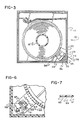
- a spool-type cartridge embodying the locking structure according to one embodiment of this invention is shown at 10.
- the cartridge is an expendable item and, as such, it is shipped separately from the utilization device. Also, it will commonly be shipped in large quantities with other cartridges.
- the cartridge has a body 11 upon or within which is rotatably mounted a spool 12 of wound web material.
- the material of the web may be extracted from the cartridge, when the cartridge is placed in suitable utilization apparatus, such as a copier or printer.
- the spool 12 is locked against rotation during shipping and handling, prior to use, by a spool latching or locking member shown generally at 20 in Figs 1 and 2.
- the locking member cooperates with suitable means associated with the spool and rotatable with the spool, in the form of a drum or bull gear 22 formed on the periphery of one of the spool end caps 23.
- the locking member 20 has a first or movable flat or leaf-like locking body portion 24 which is movable into and out of engagement with the gear 22, and further includes a second flat part in the form of a relatively fixed portion 25 rigidly mounted on the body of the spool 10.
- the movable portion 24 is provided, at one end, with gear teeth 28 in the form of a gear sector.
- the teeth 28 have a pitch line in common with that of the gear 22, and are normally held or positioned in engagement with the teeth of the gear 22.
- the member 20 engages a peripheral part of the spool 10 at the gear 22 along a substantial part of the circumference of the gear 22 and has a high beam strength to resist forces tending to cause the spool to rotate.
- connection 30 may be in the form of a transversely thinned or weakened section or line, forming an elongated bend axis about which the portion 24 may move to carry the sector teeth 28 out of locking engagement with the gear 22.
- One end of the fixed portions of the locking member 20 is firmly attached to the cartridge 10, on the ends of a pair of upstanding rigid posts 35.
- the bases of the posts are mounted on, or form an integral part of, the body 11.
- the bendable hinge 30 is therefore located between the fixed end, defined at the posts 35, and the movable portion 24.
- the hinge 30 may be reinforced by one or more small raised portions or ribs 36 on the hinge line. These ribs, during bending movement of the movable portion 24 about the hinge 30, are stressed beyond the elastic limit of the material, and thus become permanently deformed.
- the hinge 30 provides high beam strength in the direction of rotation of the spool 12, due to the fact that the locking portion 24, in the long direction of the hinge, is wide compared to the thickness of the material at the hinge. Forces tending to rotate the spool are transmitted though the body of the locking member 20 to the fixed support posts 35.
- a push pin 40 disengages the movable portion 24 of the locking member 20 from the spool 12 when the cartridge is placed in use.
- the pin 40 is part of the utilization apparatus for the cartridge.
- An access opening 42 (Fig. 2) in the body 11 of the cartridge is aligned, when the cartridge is inserted or loaded, with the path of movement of the pin 40, as shown in Fig. 2.
- the opening 42 leads to a location on the movable portion 24 about midway between the hinge 30 and the sector teeth 28, to provide mechanical advantage for the of disabling the latch.
- the movable portion 24 may be provided with light sealing means in the form of a protuberance or cup-shaped portion 45 (Fig. 2), proportioned to be tightly received in closing relation to the inside end of the opening 42.
- the protuberance at the outer surface thereof, forms a contact surface for the end of the pin 40.
- the light seal formed by the protuberance need only be effective prior to the insertion of the cartridge into the using machine, and is no longer needed once the cartridge is properly in place.
- the latching member may be desirable to provide with an initially high resistance to the disengaging movement, followed thereafter by lower resistance to movement. This is accomplished by a frangible tie down or a fuse-like connection between the body of the cartridge and the movable portion 24 of the locking structure.
- the connection offers an initially high resistance to breaking, and after being broken, permits the entire force of the pin to be effective in bending the portion 24 about the hinge connection 30.
- Such a tie down is shown in Fig. 2, as a relatively weakened connecting pin or link 48.
- One end of the link 48 is connected to the body of the cartridge, and the other end is connected to the portion 24.
- the link head 49 may fail and be withdrawn through the portion 24, or the link may be weakened just under the head 49 so as to fail under a predetermined stress.
- the link 48 provides means for retaining the locking member in an operative position with a force which exceeds that required thereafter to move the menber to an inoperative or release position.
- the latching member may be formed of the same material as that of the cartridge body.
- the fixed portion 25 may be ultrasonically welded or otherwise attached to the body, on the support pins 35.
- the utilization apparatus for the cartridge may itself provide the releasing mechanism, in the form of the pin 40.
- the protuberance 45 forming the light shield may be provided with an elongated operator or pin portion, extending out to the exterior surface of the cartridge body, or beyond, for external access and operation.
- the frangible connection formed by the link 48 to the movable latch portion 24 is broken, and the portion will pivot about the integral hinge 30, and the teeth 28 will become disengaged from the gear 22.
- the material of the hinge especially the material of the ribs 36, will be stressed beyond the elastic limit and thus permanently deformed, so that the teeth 28 on the sector end remain disengaged.
- This moved position is shown by the broken lines in Fig. 2.
- the latch mechanism may be arranged so that the moving latch portion bends inwardly or outwardly with respect to the cartridge, as desired. Even though the latch is now disabled, the movable portion remains attached to its fixed support portion 25, and is not free to become disengaged and interfere with the proper operation of the cartridge.
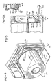
- Figs. 4-7 illustrate a second embodiment of the invention, in which the teeth of the latch member are arranged to permit the spool to turn in one direction only.
- the spool 12 may turn anti-clockwise, as viewed in Fig. 4, to retract the web material into the cartridge, but is restrained from turning clockwise and thus prevents the web material to be withdrawn from the cartridge.
- the periphery of the spool wall of the end cap 23 is formed with an annular array of inclined ratchet teeth 60. The teeth are shown as facing axially of the spool 12.
- the locking member 61 is formed with a movable sector portion 62, the remote end of which is formed with ratchet teeth 63 which mesh with the teeth 60 of the spool.
- the teeth 63 are biased by the latch support into engagement with the teeth of the spool. Spool rotation in the ratcheting direction is accomplished by limited deflection of the movable member 61.
- the member 61 of this embodiment is formed with an integral leaf or tongue 65 attached to the remainder of the member only along a hinge 66 (Fig. 7), and otherwise cut out of the member 61 and forming a generally U-shaped clearance 67 with the member 61.
- the body of the locking member can effectively rock about the tongue 65 by bending at the hinge 66.
- the member 61 is rigidly attached to the cartridge body 11A on a pair of support posts 68.
- a fuse or frangible line or connection 70 similar in function to the link head 49 of the preceding embodiment, retains the locking member 61 in its latching position until a predetermined force is applied by a push pin 40A through an operating access opening 72.
- the member 61 may also be formed with a light-sealing protuberance 75, having the same general configuration and function as the protuberance 45 above, and thus forms a bearing surface for the end of the pin 40A.
- the operation of this embodiment is similar to that previously described.
- the pin 40A which may be part of the cartridge utilization apparatus, engages the light seal and protuberance 75 with sufficient force to break the connection with the link 70 and cause the locking member 61 to rock about the hinge 66 at the leaf 65, as shown in Fig. 5A.
- the material of the hinge 66 is stressed beyond its elastic limit, resulting in the disengagement of the ratchet teeth 63 with the teeth 60 of the spool, with a rocking movement of the latch member on the leaf sufficient to prevent subsequent reengagement.
Landscapes
- Physics & Mathematics (AREA)
- General Physics & Mathematics (AREA)
- Engineering & Computer Science (AREA)
- Microelectronics & Electronic Packaging (AREA)
- Packaging Of Annular Or Rod-Shaped Articles, Wearing Apparel, Cassettes, Or The Like (AREA)
- Unwinding Webs (AREA)
- Details Of Cameras Including Film Mechanisms (AREA)
- Storage Of Web-Like Or Filamentary Materials (AREA)
Applications Claiming Priority (2)
| Application Number | Priority Date | Filing Date | Title |
|---|---|---|---|
| US209714 | 1980-11-24 | ||
| US07/209,714 US4802633A (en) | 1988-06-22 | 1988-06-22 | Movable cartridge lock |
Publications (2)
| Publication Number | Publication Date |
|---|---|
| EP0348192A2 true EP0348192A2 (de) | 1989-12-27 |
| EP0348192A3 EP0348192A3 (de) | 1991-05-15 |
Family
ID=22779959
Family Applications (1)
| Application Number | Title | Priority Date | Filing Date |
|---|---|---|---|
| EP19890306296 Withdrawn EP0348192A3 (de) | 1988-06-22 | 1989-06-22 | Magazin vom Spulentyp mit Verschluss |
Country Status (5)
| Country | Link |
|---|---|
| US (1) | US4802633A (de) |
| EP (1) | EP0348192A3 (de) |
| JP (1) | JPH0240636A (de) |
| KR (1) | KR900000894A (de) |
| CN (1) | CN1038993A (de) |
Cited By (2)
| Publication number | Priority date | Publication date | Assignee | Title |
|---|---|---|---|---|
| EP0572338A1 (de) * | 1992-05-29 | 1993-12-01 | Eastman Kodak Company | Rückdrehsperre für Bandkassetten |
| NL1001870C2 (nl) * | 1995-12-11 | 1997-06-12 | Polychrome Chemco | Houder voor velmateriaal op een rol. |
Families Citing this family (31)
| Publication number | Priority date | Publication date | Assignee | Title |
|---|---|---|---|---|
| US6074107A (en) * | 1988-10-31 | 2000-06-13 | Canon Kabushiki Kaisha | Camera system |
| EP0414269B1 (de) * | 1989-08-25 | 1995-03-08 | Fuji Photo Film Co., Ltd. | Kassette für einen fotografischen Film |
| US5014923A (en) * | 1990-04-09 | 1991-05-14 | Eastman Kodak Company | Web-spool for a cartridge |
| US5064134A (en) * | 1990-05-07 | 1991-11-12 | Eastman Kodak Company | Film cassette with film exposure status indicator |
| US5021816A (en) * | 1990-05-07 | 1991-06-04 | Eastman Kodak Company | Camera apparatus for use with film cassette having film exposure status indicator |
| US5003334A (en) * | 1990-05-07 | 1991-03-26 | Eastman Kodak Company | Film cassette with film exposure status indicator |
| US5049913A (en) * | 1990-07-31 | 1991-09-17 | Eastman Kodak Company | Film cassette with locking means for exposure status indicator |
| US5156354A (en) * | 1990-09-10 | 1992-10-20 | Eastman Kodak Company | Web-roll anti-clockspringing mechanism |
| US5079579A (en) * | 1990-10-11 | 1992-01-07 | Eastman Kodak Company | Camera apparatus for use with film cassette having locking means for exposure status indicator |
| US5261623A (en) * | 1992-05-29 | 1993-11-16 | Eastman Kodak Company | Anti-clockspringing mechanism for a web roll cassette |
| US5275346A (en) * | 1992-05-29 | 1994-01-04 | Eastman Kodak Company | Web cassette for holding and dispensing a roll of web material |
| US5332169A (en) * | 1992-10-01 | 1994-07-26 | Eastman Kodak Company | Method of preventing clockspringing of a wound web within a cassette |
| US5335873A (en) * | 1992-10-01 | 1994-08-09 | Eastman Kodak Company | Cassette for web material |
| US5314134A (en) * | 1992-11-19 | 1994-05-24 | Eastman Kodak Company | Anti-clockspringing cassette for a roll of web material and method |
| US5359378A (en) * | 1994-01-13 | 1994-10-25 | Eastman Kodak Company | Film cassette with lockable light shield |
| US5357303A (en) * | 1994-02-17 | 1994-10-18 | Eastman Kodak Company | Film cassette with lockable light shield |
| US6089486A (en) * | 1999-04-15 | 2000-07-18 | Eastman Kodak Company | Film cartridge with pawl and ratchet |
| CN100398930C (zh) * | 2003-04-30 | 2008-07-02 | 乐金电子(天津)电器有限公司 | 空调机的空气排出装置 |
| US7040564B1 (en) * | 2003-12-26 | 2006-05-09 | Storage Technology Corporation | Cartridge reel with internal reel assembly lock |
| US7341214B2 (en) * | 2005-06-30 | 2008-03-11 | Stratasys, Inc. | Cassette spool lock |
| US8395647B2 (en) | 2010-07-29 | 2013-03-12 | Brady Worldwide, Inc. | Printer with pivotable platen |
| US8734035B2 (en) | 2010-07-29 | 2014-05-27 | Brady Worldwide, Inc. | Media cartridge with shifting ribs |
| US8714471B2 (en) | 2010-07-29 | 2014-05-06 | Brady Worldwide, Inc. | Friction core brake |
| US9102180B2 (en) | 2010-07-29 | 2015-08-11 | Brady Worldwide, Inc. | Cartridge assembly with ribbon lock |
| US9108449B2 (en) | 2010-07-29 | 2015-08-18 | Brady Worldwide, Inc. | Cartridge assembly with edge protector |
| USD692048S1 (en) | 2011-07-19 | 2013-10-22 | Brady Worldwide, Inc. | Printer device |
| CN104444621A (zh) * | 2014-11-17 | 2015-03-25 | 上海外高桥造船有限公司 | 用于潜水泵的电缆绞车 |
| JP6601080B2 (ja) * | 2015-09-11 | 2019-11-06 | カシオ計算機株式会社 | 印刷装置、及び、印刷方法 |
| CN107889666A (zh) * | 2017-06-14 | 2018-04-10 | 广西南宁尼科安全技术服务有限公司 | 一种改进型植物遮光装置 |
| CN107889667A (zh) * | 2017-06-14 | 2018-04-10 | 广西南宁尼科安全技术服务有限公司 | 一种新型植物遮光装置 |
| CN107889668A (zh) * | 2017-06-14 | 2018-04-10 | 广西南宁尼科安全技术服务有限公司 | 一种使用简便的园林植物遮光装置 |
Family Cites Families (15)
| Publication number | Priority date | Publication date | Assignee | Title |
|---|---|---|---|---|
| US3613876A (en) * | 1969-11-24 | 1971-10-19 | Eastman Kodak Co | Anticlockspring device and method |
| US3807840A (en) * | 1972-01-03 | 1974-04-30 | Polaroid Corp | Film handling cassette having reel locking means |
| US3784001A (en) * | 1972-02-14 | 1974-01-08 | Eastman Kodak Co | Anticlockspring connector |
| FR2246892A1 (en) * | 1973-10-03 | 1975-05-02 | Fuji Photo Optical Co Ltd | Magazine for roll film camera - has wind-up spool with ratchet locking spool when out of camera and permits correct sense rotation |
| US4394989A (en) * | 1981-04-30 | 1983-07-26 | Minnesota Mining And Manufacturing Company | Adjustable endless loop tape cartridge with shipping lock |
| US4403845A (en) * | 1980-12-09 | 1983-09-13 | Agfa-Gevaert N.V. | Cassette for holding and dispensing a roll of web material |
| IE821086L (en) * | 1982-05-06 | 1983-11-06 | Eko Video Ltd | Magnetic tape cassette |
| JPS5942676A (ja) * | 1982-09-02 | 1984-03-09 | Fuji Photo Film Co Ltd | 磁気テ−プカセツト |
| JPS5992478U (ja) * | 1982-12-14 | 1984-06-22 | 日立マクセル株式会社 | テ−プカ−トリツジ |
| JPS60133580A (ja) * | 1983-12-22 | 1985-07-16 | Sony Corp | テ−プカセツト |
| DE3421407C1 (de) * | 1984-06-08 | 1985-12-19 | Triumph-Adler Aktiengesellschaft für Büro- und Informationstechnik, 8500 Nürnberg | Farbbandkassette fuer Schreib- oder aehnliche Maschinen |
| DE8420207U1 (de) * | 1984-07-06 | 1984-11-29 | Basf Ag, 6700 Ludwigshafen | Bandkassette, insbesondere magnetbandkassette |
| JPS6129472A (ja) * | 1984-07-21 | 1986-02-10 | Sony Corp | 磁気テ−プカセツト |
| JPH0348783Y2 (de) * | 1984-10-12 | 1991-10-17 | ||
| EP0270486B1 (de) * | 1986-10-29 | 1991-03-06 | Ilford Ag | Tageslichtkassette |
-
1988
- 1988-06-22 US US07/209,714 patent/US4802633A/en not_active Expired - Fee Related
-
1989
- 1989-06-19 JP JP1154763A patent/JPH0240636A/ja active Pending
- 1989-06-21 KR KR1019890008540A patent/KR900000894A/ko not_active Withdrawn
- 1989-06-21 CN CN89104246A patent/CN1038993A/zh active Pending
- 1989-06-22 EP EP19890306296 patent/EP0348192A3/de not_active Withdrawn
Cited By (4)
| Publication number | Priority date | Publication date | Assignee | Title |
|---|---|---|---|---|
| EP0572338A1 (de) * | 1992-05-29 | 1993-12-01 | Eastman Kodak Company | Rückdrehsperre für Bandkassetten |
| NL1001870C2 (nl) * | 1995-12-11 | 1997-06-12 | Polychrome Chemco | Houder voor velmateriaal op een rol. |
| EP0785156A1 (de) * | 1995-12-11 | 1997-07-23 | Sun Chemical Corporation | Halter für Filmmaterial auf einem Wickelkern |
| US5868339A (en) * | 1995-12-11 | 1999-02-09 | Kodak Polychrome Graphics | Holder for preventing the incidental rotation of film material on a role |
Also Published As
| Publication number | Publication date |
|---|---|
| US4802633A (en) | 1989-02-07 |
| KR900000894A (ko) | 1990-01-31 |
| JPH0240636A (ja) | 1990-02-09 |
| EP0348192A3 (de) | 1991-05-15 |
| CN1038993A (zh) | 1990-01-24 |
Similar Documents
| Publication | Publication Date | Title |
|---|---|---|
| EP0348192A2 (de) | Magazin vom Spulentyp mit Verschluss | |
| US5193759A (en) | Film or paper cassette | |
| EP1260984B1 (de) | Magnetbandkassette | |
| CN103786604B (zh) | 座椅锁设备 | |
| JPS6288813A (ja) | ロツド保持装置 | |
| US5436782A (en) | Magnetic-tape cassette and reel-locking device suitable for use in the magnetic-tape cassette | |
| US5211491A (en) | Thermal transfer cartridge integral lock | |
| EP0335549B1 (de) | Bandkassette mit Spulen-Verriegelungsmittel | |
| JPS5894865A (ja) | 安全ベルトの自動固定巻取機 | |
| JPS6099740A (ja) | 組み立てが容易なシ−ト・ベルト巻き込み装置 | |
| JPH0749550A (ja) | フィルムカセット | |
| JP2000511682A (ja) | 少なくとも1個の軸線方向に移動自在のリール及びリールの軸線方向移動を阻止する阻止手段を有するカセット | |
| US4179028A (en) | Casing | |
| US5564643A (en) | Photo film cassette having a film trailer attaching assembly | |
| US6502776B2 (en) | Tape leader member in a single-reel tape cartridge | |
| US5146380A (en) | Reel lock mechanism for tape cassette | |
| JPH0474222B2 (de) | ||
| GB2163392A (en) | Security seal | |
| US4749144A (en) | Emergency locking retractor for seat belts | |
| US4678140A (en) | Tape cassette having a mounting for a leg spring for a reel brake spring | |
| US5449125A (en) | Film spool with internal flexures to engage and release film end | |
| EP0558066B1 (de) | Magnetbandkassette | |
| US5133456A (en) | Lock ring for tape-like recording media wound as a roll of tape, in particular magnetic tapes | |
| JPS6322751A (ja) | 予め応力を与えたばねを備えたバレル | |
| JPH0536679U (ja) | 磁気テープカートリツジ |
Legal Events
| Date | Code | Title | Description |
|---|---|---|---|
| PUAI | Public reference made under article 153(3) epc to a published international application that has entered the european phase |
Free format text: ORIGINAL CODE: 0009012 |
|
| AK | Designated contracting states |
Kind code of ref document: A2 Designated state(s): DE FR GB |
|
| PUAL | Search report despatched |
Free format text: ORIGINAL CODE: 0009013 |
|
| AK | Designated contracting states |
Kind code of ref document: A3 Designated state(s): DE FR GB |
|
| STAA | Information on the status of an ep patent application or granted ep patent |
Free format text: STATUS: THE APPLICATION IS DEEMED TO BE WITHDRAWN |
|
| 18D | Application deemed to be withdrawn |
Effective date: 19920102 |