EP0348060B1 - Kupplungsanordnung für Bewehrungsstäbe - Google Patents
Kupplungsanordnung für Bewehrungsstäbe Download PDFInfo
- Publication number
- EP0348060B1 EP0348060B1 EP89305638A EP89305638A EP0348060B1 EP 0348060 B1 EP0348060 B1 EP 0348060B1 EP 89305638 A EP89305638 A EP 89305638A EP 89305638 A EP89305638 A EP 89305638A EP 0348060 B1 EP0348060 B1 EP 0348060B1
- Authority
- EP
- European Patent Office
- Prior art keywords
- sleeve
- engagers
- ribs
- bars
- wires
- Prior art date
- Legal status (The legal status is an assumption and is not a legal conclusion. Google has not performed a legal analysis and makes no representation as to the accuracy of the status listed.)
- Expired - Lifetime
Links
Images
Classifications
-
- E—FIXED CONSTRUCTIONS
- E04—BUILDING
- E04C—STRUCTURAL ELEMENTS; BUILDING MATERIALS
- E04C5/00—Reinforcing elements, e.g. for concrete; Auxiliary elements therefor
- E04C5/16—Auxiliary parts for reinforcements, e.g. connectors, spacers, stirrups
- E04C5/162—Connectors or means for connecting parts for reinforcements
- E04C5/163—Connectors or means for connecting parts for reinforcements the reinforcements running in one single direction
- E04C5/165—Coaxial connection by means of sleeves
-
- F—MECHANICAL ENGINEERING; LIGHTING; HEATING; WEAPONS; BLASTING
- F16—ENGINEERING ELEMENTS AND UNITS; GENERAL MEASURES FOR PRODUCING AND MAINTAINING EFFECTIVE FUNCTIONING OF MACHINES OR INSTALLATIONS; THERMAL INSULATION IN GENERAL
- F16B—DEVICES FOR FASTENING OR SECURING CONSTRUCTIONAL ELEMENTS OR MACHINE PARTS TOGETHER, e.g. NAILS, BOLTS, CIRCLIPS, CLAMPS, CLIPS OR WEDGES; JOINTS OR JOINTING
- F16B7/00—Connections of rods or tubes, e.g. of non-circular section, mutually, including resilient connections
- F16B7/04—Clamping or clipping connections
- F16B7/0406—Clamping or clipping connections for rods or tubes being coaxial
- F16B7/0426—Clamping or clipping connections for rods or tubes being coaxial for rods or for tubes without using the innerside thereof
-
- Y—GENERAL TAGGING OF NEW TECHNOLOGICAL DEVELOPMENTS; GENERAL TAGGING OF CROSS-SECTIONAL TECHNOLOGIES SPANNING OVER SEVERAL SECTIONS OF THE IPC; TECHNICAL SUBJECTS COVERED BY FORMER USPC CROSS-REFERENCE ART COLLECTIONS [XRACs] AND DIGESTS
- Y10—TECHNICAL SUBJECTS COVERED BY FORMER USPC
- Y10T—TECHNICAL SUBJECTS COVERED BY FORMER US CLASSIFICATION
- Y10T403/00—Joints and connections
- Y10T403/16—Joints and connections with adjunctive protector, broken parts retainer, repair, assembly or disassembly feature
- Y10T403/1616—Position or guide means
-
- Y—GENERAL TAGGING OF NEW TECHNOLOGICAL DEVELOPMENTS; GENERAL TAGGING OF CROSS-SECTIONAL TECHNOLOGIES SPANNING OVER SEVERAL SECTIONS OF THE IPC; TECHNICAL SUBJECTS COVERED BY FORMER USPC CROSS-REFERENCE ART COLLECTIONS [XRACs] AND DIGESTS
- Y10—TECHNICAL SUBJECTS COVERED BY FORMER USPC
- Y10T—TECHNICAL SUBJECTS COVERED BY FORMER US CLASSIFICATION
- Y10T403/00—Joints and connections
- Y10T403/47—Molded joint
Definitions
- the present invention relates to the coupling of reinforcing bars and is particularly but not exclusively concerned with end-coupling and fixing reinforcing bars, usually of steel, for use in structural concrete or the like.
- a reinforcing bar coupling system in which a settable material (resin) is applied about adjacent bars in end to end relationship, at a desired joint or junction, within a material retaining sleeve having spacing means for its fitting about said ends.
- the spacing means comprises radially spaced engagers at least one of which is positively adjustable through the sidewall, wherein at emplacement the sleeve is centred relative to said bars.
- the positively adjustable engager comprises a screw threaded bolt with two other engagers as a pair of ribs or nibs.
- the aim is to achieve a joint strength at least equal to the ultimate tensile strength of the reinforcing bar.
- a joint strength at least equal to the ultimate tensile strength of the reinforcing bar.
- FR-A-2406045 describes a sleeve-like coupling having apertures in the sidewalls thereof to receive U-shaped elements entrant substantially tangentially and whose limbs are tapered and stepped to cooperate with the sleeve and grip opposite portions of the bar or wires.
- a coupling fitting for making joints in reinforcing bars or wires for structural concrete comprising a sleeve-like device having means for locating it over and about portions of said bars or wires adjacent said desired joint with clearance to said bar or wire portions, wherein the means for locating comprises for each portion engagers at radial spacings relative to axes of bars or wires to be joined, one of which engagers for each portion is positively adjustable at emplacement through the sidewall of the device, and the other engagers comprise radially spaced ribs in the form of longitudinal strips, and wherein those ribs are profiled to key into the bars or wires portions.
- the profiling of the ribs aids in achieving the design strength by way of a mechanical connection of the bars or wires.
- Means may be provided for physically spacing the ribs at desired circumferential spacings within the sleeve, usually opposite to the positively adjustable engager.
- Such means may comprise a cage-like structure such as by small diameter wire or rod spacers simply positioned between or physically secured to two ribs.
- the ribs may be secured to the inner wall of the sleeve at desired circumferential spacing by adhesive, or by tack welding at the or each end of the sleeve.
- tack welding at the or each end of the sleeve.
- the sleeve may be splined longitudinally to receive the ribs.
- Such splining may provide for radial location of the ribs by appropriate cross-sectioning i.e. with a mouth narrower than the root.
- pairs of ribs are disposed symmetrically about the axis of the positive engager, but on the opposite half of the sleeve.
- a minimum angle between pairs of ribs of 100 degrees and a maximum of 180 degrees although, smaller angles may be used.
- one pair is perfectly satisfactory and enables load to be achieved easily.
- the ribs we prefer to harden the ribs, so that they are greater than the hardness of the reinforcing bars and the sleeve.
- the commonly used ribbed reinforcing bars have a hardness of 110 Vickers and we prefer the sleeve to have the same hardness.
- a profile hardness in the range 250-400 Vickers is suitable and we have found that a profile hardness of 300 Vickers gives optimum results.
- the hardening can be by any convenient means usually by heating to 850 degrees C and cooling in either water or oil depending on the degree of hardness. Heating in a nitrogen atmosphere gives a preferred quality of hardness. Work hardening alone gives a hardness of 120 Vickers and this may be satisfactory in certain applications such as with mild steel reinforcing bars (usually non-ribbed) which are of lower hardness.
- the profiling gives indentation of the ribs into the reinforcing bar and/or the sleeve at a plurality of positions along the length of the rib, and it is these indentations which effectively produce a plurality of mechanical connections along the length of the coupling, producing significant increases in mechanical strength, compared with our previous construction which did not utilise mechanical keying of the ribs.
- the hardening of the ribs gives rise to penetration to thereby ensure adequate keying. Tensile tests to destruction on the couplings have shown that the ribs remain intact with the surface of the reinforcing bar being scoured by the teeth.
- the positively adjustable engagers for each portion at least one screw or bolt threaded through the wall of the sleeve.
- the wall thickness of the sleeve is such that it avoids canting of the bolt in the bore under load.
- the engagers configured to bite into the reinforcing bars.
- a point or indent to the end of the bolt is useful in this regard so as to provide a biting point or edge.
- a conical end or annular edge to the screw or bolt gives keying into the surface of the reinforcing bar and this can contribute in the region of 60% of the mechanical strength, with the keying of the ribs providing of the order of 40% of the mechanical strength.
- the screw/bolt is done up so as to both centre the bars relative to the sleeve and to get the desired mechanical keying.
- the torque is selected in relation to the size of coupling to give the desired mechanical strength.
- We have tried using further pointed adjustable engagers in place of the ribs but find it is almost invariably impossible to get at the bolt heads on-site to do these up. Accordingly using one pair of ribs and positively adjustable engagers at one circumferential location particularly advantageous.
- the length of the couplings and the number of positive engagers per portion of bar is chosen independence upon the size of bar or wire being joined and/or in relation to the maximum design load. The two factors may be equated one with the other depending on the safety factor.
- Three bolts per portion is typical for 10-12 mm bar.
- the invention also provides a method of coupling reinforcing bars or wires for subsequent embedment in concrete for structural purposes, the method comprising applying about adjacent bar or wire portions at a desired joint or junction a sleeve having locating means for its fitting about said portions in spaced relation thereto, the locating means comprising for each portion radially spaced engagers, at least one of which for each portion is positively adjustable through the sidewall of the sleeve and others of which comprise profiled ribs in the form of longitudinal strips, and wherein at emplacement the sleeve is centred relative to each of said portions to be joined by adjustment of said at least one positively adjustable engagers to give rise to keying engagement between said engagers and the bar or wire portions to give a structurally sound joint.
- the method further comprises applying about the adjacent wire or bar portions at the desired joint or junction thereof settable material, which material is applied within the sleeve which serves as a material retaining sleeve, and when said material is cause or allowed to set affords a structurally sound joint between and over said adjacent portions.
- a suitable injectable settable material may be introduced into the sleeve fitting via any of a plurality of holes, even valved ports, located in the sleeve fitting and also preferably serving as sight holes for checking injections.
- the sleeve fitting has sealing means at each end portion to prevent loss of settable material.
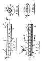
- a coupling fitting for use in securing together ends of reinforcing bars or wires for subsequent embedment in structural concrete, comprises a tubular sleeve 1 having an internal diameter such as to fit about end portions of bars or wires in spaced relation thereto.
- the sleeve has internal helical grooving 2, say 10 mm pitch.
- Holes 3, 4 are provided in the walls of the sleeve adjacent opposite ends, provided as sighting and/or filling hole as described further hereinafter.
- Nylon plugs 11 are provided to block the holes 3, 4 and are transparent to act as windows to see that resin is in place.
- the sleeve is constructed symmetrically about its mid-point and in the illustrated embodiment has for each half, three threaded holes 5 through the wall for positively adjustable engagers, in the form of threaded screws or bolts 7 spaced along the coupling. These are preferably cap screws, and with reduced shanks as at 8 so that the head shears off at a predetermined torque on screwing in place.
- the end of the bolts 7 are so formed with indentation means 9 to penetrate into the bar or wires on doing up, either as a tapered point, or a convex or concave formation providing either a biting point or an annular biting edge.
- two longitudinal ribs 13 are provided acting as radial engagers with which the bar or wire portions abut in use.
- the ribs are spaced apart circumferentially by angle A, which is in the range of 0 to 180 degrees, preferably of the order of 120 degrees where just two ribs are provided.
- the ribs are positioned straddling the axis 15 of the positively adjustable engagers 7 and in the opposite half of the sleeve. In other embodiments, two or more pairs of ribs are provided.
- the ribs run substantially the length of the sleeve, with soft tack welding 17 at each end which provides a convenient means of locating the ribs to the sleeve longitudinally and circumferentially during emplacement, which is often in a vertical orientation.
- the profiling is formed by upstanding teeth having inclined flanks symmetrical about an axis perpendicular to the longitudinal axis of the profiled engagers. The profiling is shown diagrammatically in Figure 2.
- a typical reinforcing bar is formed both with diametrically opposed longitudinal ribbing and part helical ribs, with these to each half of the bar, as defined by the longitudinal ribbing, being inclined opposite to one another.
- the mechanical strength of the coupling depends to some extent on the positional relationship of the bar with respect to the radial engagers. In theory the best performance results where our profiled rib is aligned with the longitudinal rib of the bar, thus giving contact points all along the length of the rib. The other engager, then must contact along the helical ribbing of the bar. However, we have found that contact of both radial engagers with only the helical ribbing gives virtually the same mechanical performance.
- the ribs have a hardness in the range 250-400 Vickers, preferably 300 Vickers which is harder than the reinforcing bars so as to ensure adequate penetration.
- the coupling sleeve is fitted over and about adjacent ends (butting up to one another for a straight sleeve) and the positive engagers done up so centring the bars within the sleeve and causing the radial engagers to key into the bars, also the sleeve where the ribs are profiled to both sides.
- the ends of the positively adjustable engagers also bite into the bars.
- the bolts 7 shear off at the outer surface of the sleeve at a torque determined to give required cooperating engagement of the engagers with the bar and/or sleeve. Such an arrangement provides the required mechanical strength.
- the invention has been described with reference to a straight butt joint in which a straight sleeve is employed. This is probably the most common joint configuration, but the invention also extends to sleeve-like devices for coupling bars or wires at angles to one another, by suitable configuration of the sleeve to receive appropriately orientated ends of bars or wires.
Landscapes
- Engineering & Computer Science (AREA)
- Architecture (AREA)
- General Engineering & Computer Science (AREA)
- Civil Engineering (AREA)
- Structural Engineering (AREA)
- Mechanical Engineering (AREA)
- Reinforcement Elements For Buildings (AREA)
- Paper (AREA)
- Superconductors And Manufacturing Methods Therefor (AREA)
- Compositions Of Oxide Ceramics (AREA)
- Pens And Brushes (AREA)
Claims (14)
Applications Claiming Priority (2)
| Application Number | Priority Date | Filing Date | Title |
|---|---|---|---|
| GB888814729A GB8814729D0 (en) | 1988-06-21 | 1988-06-21 | Reinforcing bar coupling system |
| GB8814729 | 1988-06-21 |
Publications (2)
| Publication Number | Publication Date |
|---|---|
| EP0348060A1 EP0348060A1 (de) | 1989-12-27 |
| EP0348060B1 true EP0348060B1 (de) | 1991-09-11 |
Family
ID=10639069
Family Applications (1)
| Application Number | Title | Priority Date | Filing Date |
|---|---|---|---|
| EP89305638A Expired - Lifetime EP0348060B1 (de) | 1988-06-21 | 1989-06-05 | Kupplungsanordnung für Bewehrungsstäbe |
Country Status (11)
| Country | Link |
|---|---|
| US (1) | US5046878A (de) |
| EP (1) | EP0348060B1 (de) |
| AT (1) | ATE67265T1 (de) |
| AU (1) | AU613767B2 (de) |
| CA (1) | CA1314404C (de) |
| DE (1) | DE68900257D1 (de) |
| ES (1) | ES2025842T3 (de) |
| GB (2) | GB8814729D0 (de) |
| GR (1) | GR3003313T3 (de) |
| HK (1) | HK119796A (de) |
| SG (1) | SG41975G (de) |
Cited By (3)
| Publication number | Priority date | Publication date | Assignee | Title |
|---|---|---|---|---|
| DE4344344A1 (de) * | 1993-01-11 | 1994-07-14 | Krauss Kaminwerke Muenchen Gei | Kamin mit mehreren, durch Verbindungsanordnungen biegesteif miteinander verbundenen Kaminelementen |
| DE29500727U1 (de) * | 1995-01-18 | 1995-03-16 | Pfeifer Seil- und Hebetechnik GmbH & Co, 87700 Memmingen | Vorrichtung für eine Verbindung eines Zugelementes mit einem Armierungsstab eines Betonfertigteiles |
| DE102007028255A1 (de) * | 2007-06-20 | 2008-12-24 | Schiedel Ag | Haltevorrichtung für durch Gebäude- oder Raumabdeckungen hindurchreichende Leitungen, wie Schornsteine |
Families Citing this family (40)
| Publication number | Priority date | Publication date | Assignee | Title |
|---|---|---|---|---|
| US5393165A (en) * | 1990-10-29 | 1995-02-28 | Rowan, Jr.; Robert L. | Anchor bolt repair coupling with preloading jack and epoxy injection |
| GB9200446D0 (en) * | 1992-01-10 | 1992-02-26 | Metal Bond Tech Ltd | Reinforcing bar coupling |
| FR2698404B1 (fr) * | 1992-11-25 | 1995-02-03 | Coutier Ind | Echelle de sécurité et son procédé d'assemblage in situ. |
| US5383740A (en) * | 1993-08-02 | 1995-01-24 | Richmond Screw Anchor Company | Combination mechanical/grout sleeve coupling for concrete reinforcement bars |
| FR2721641B1 (fr) * | 1994-06-28 | 1996-08-02 | Mure Ets | Tête de tirant d'ancrage. |
| US5664902A (en) * | 1995-01-26 | 1997-09-09 | Barsplice Products, Inc. | Tubular coupler for concrete reinforcing bars |
| US5909980A (en) * | 1995-01-26 | 1999-06-08 | Barsplice Products, Inc. | Tubular coupler for concrete reinforcing bars |
| FR2731028B1 (fr) | 1995-02-23 | 1997-04-18 | Mure Ets | Dispositif de liaison de barres d'armature a haute adherence pour beton arme, et procede pour son obtention |
| JP3237050B2 (ja) * | 1995-11-10 | 2001-12-10 | 東京鐵鋼株式会社 | モルタル充填式鉄筋継手 |
| US6481102B1 (en) | 1999-12-02 | 2002-11-19 | Tommie D. Hill | Attachment devices, systems, and methods for a tendon, rod, or other elongated member |
| AU5366100A (en) | 1999-12-08 | 2001-06-14 | Suntisuk Dr Plooksawasdi | Self coupling steel bar connections |
| EP1191164A4 (de) * | 2000-03-02 | 2004-03-10 | Anderson Technology Corp | Verbindungsanordnung für mehrfaserige stahlkabel und herstellungsmethode für diese |
| ES2237351T3 (es) | 2002-05-01 | 2007-04-01 | Ultimate Design Solutions Ltd. | Dispositivo de acoplamiento. |
| DE50301426D1 (de) * | 2003-05-26 | 2006-03-02 | Halfen Gmbh & Co Kg | Vorrichtung zum Verbinden von Stabenden |
| US7624556B2 (en) * | 2003-11-25 | 2009-12-01 | Bbv Vorspanntechnik Gmbh | Threaded deformed reinforcing bar and method for making the bar |
| US20050169701A1 (en) * | 2003-12-18 | 2005-08-04 | Kies Antonius M. | Reinforcing bar splice and method |
| US20060067785A1 (en) * | 2004-09-30 | 2006-03-30 | Barsplice Products, Inc. | Tubular coupler for concrete reinforcing bars |
| EP1898017A1 (de) * | 2006-09-08 | 2008-03-12 | Dextra Asia | Vorrichtung zum Verbinden von Stabenden |
| US20080172979A1 (en) * | 2007-01-19 | 2008-07-24 | Wilson Eric J | Reinforcing bar splice with cutting edge bolts |
| GB2443823B (en) * | 2007-04-12 | 2008-11-12 | Denmay Steel | Devices and methods for use in construction |
| WO2009092019A1 (en) * | 2008-01-16 | 2009-07-23 | Weaver Jason M | Bar coupling apparatus and methods |
| US8413396B2 (en) * | 2009-08-11 | 2013-04-09 | Wisconsin Alumni Research Foundation | Splice system for connecting rebars in concrete assemblies |
| US20130209192A1 (en) | 2010-06-24 | 2013-08-15 | Nucor Corporation | Tensionable threaded rebar bolt |
| US9010165B2 (en) | 2011-01-18 | 2015-04-21 | Nucor Corporation | Threaded rebar manufacturing process and system |
| EP3265621A4 (de) * | 2015-03-02 | 2018-12-19 | Al-tuhami, Al-tuhami Abuzeid | Gitterträgerbewehrung und deren mechanische kopplerverbindungen für strukturbeton |
| USD814912S1 (en) | 2016-08-08 | 2018-04-10 | Reigstad & Associates, Inc. | Post-tension concrete splicing device |
| USD813023S1 (en) * | 2016-08-08 | 2018-03-20 | Reigstad & Associates, Inc. | Post-tension concrete splicing device |
| KR102643969B1 (ko) | 2016-09-12 | 2024-03-05 | 쿠플러 솔루션즈 리미티드 | 결합 장치, 연관된 부품들, 및 그것의 사용 방법 |
| CN109235780A (zh) * | 2018-10-22 | 2019-01-18 | 北京工业大学 | 一种适用于高烈度区的半灌浆连接套筒及其施作方法 |
| WO2020122738A1 (en) * | 2018-12-12 | 2020-06-18 | Holmes Solutions Limited Partnership | A coupling device, associated parts, tools and methods of use thereof |
| US11359376B2 (en) * | 2019-05-14 | 2022-06-14 | John C. Tutino | Threaded rod coupling with main receptacle and one or more receptacles extending therefrom at an angle |
| RU2723111C1 (ru) * | 2019-06-27 | 2020-06-08 | Владимир Павлович Блажко | Муфта для соединения выпусков арматуры сборных колонн |
| CN111827681B (zh) * | 2020-07-23 | 2021-12-03 | 吉林省飞达杭萧建筑科技有限公司 | 一种纵向预制构件灌浆工艺 |
| CN111827582A (zh) * | 2020-07-24 | 2020-10-27 | 江苏建筑职业技术学院 | 一种灌浆套筒 |
| CN112854608A (zh) * | 2021-02-23 | 2021-05-28 | 夏华强 | 一种钢筋快接套筒 |
| US12049765B2 (en) | 2021-07-20 | 2024-07-30 | Life Coded, Llc | Portable hot swaged coupling device for connecting articles |
| CN217336640U (zh) * | 2022-05-07 | 2022-09-02 | 叶丽芬 | 一种用张力完成连接的分段式拱棚 |
| CN119173670A (zh) | 2022-05-12 | 2024-12-20 | 合同制铁株式会社 | 螺纹节钢筋用耦合器及具备该耦合器的螺纹节钢筋 |
| EP4636189A1 (de) | 2024-04-17 | 2025-10-22 | Hilti Aktiengesellschaft | Kopplung von länglichen elementen unter verwendung eines mehrkomponenten-harzmörtelsystems |
| EP4636188A1 (de) | 2024-04-17 | 2025-10-22 | Hilti Aktiengesellschaft | Kopplung von länglichen elementen unter verwendung eines mehrkomponenten-mörtelsystems auf basis von blockiertem calciumaluminatzement |
Family Cites Families (11)
| Publication number | Priority date | Publication date | Assignee | Title |
|---|---|---|---|---|
| BE480929A (de) * | ||||
| US1689281A (en) * | 1923-10-29 | 1928-10-30 | Forssell Carl Abraham | Joint in iron structures and reenforcing members |
| US1913589A (en) * | 1931-07-24 | 1933-06-13 | Pelton Water Wheel Co | Shaft coupling |
| GB631786A (en) * | 1947-11-27 | 1949-11-09 | Geo H Gascoigne Company Ltd | Improvements relating to jointing means for structures built-up of cylindrical section tubes or bars |
| US3376060A (en) * | 1964-12-14 | 1968-04-02 | Shinko Wire Co Ltd | Metallic member and joint assembly |
| FR1439056A (fr) * | 1965-02-03 | 1966-05-20 | Système d'assemblage d'échafaudages métalliques mobiles | |
| GB1578328A (en) * | 1976-05-14 | 1980-11-05 | Ccl Systems Ltd | Compressing of a sleeve on to concrete-reinforcing bars |
| US4127354A (en) * | 1977-10-12 | 1978-11-28 | Amp Incorporated | Rebar securing device |
| GB2065258A (en) * | 1979-12-14 | 1981-06-24 | Press Components Co Ltd | Sleeve coupling for a pair of scaffolding members |
| US4666326A (en) * | 1982-09-11 | 1987-05-19 | Metal Bond (Technology) Limited | Reinforcing bar coupling system |
| US4662806A (en) * | 1983-11-17 | 1987-05-05 | Reed International, Incorporated | Metal lock system and method |
-
1988
- 1988-06-21 GB GB888814729A patent/GB8814729D0/en active Pending
-
1989
- 1989-06-05 GB GB8912911A patent/GB2220241B/en not_active Expired - Lifetime
- 1989-06-05 EP EP89305638A patent/EP0348060B1/de not_active Expired - Lifetime
- 1989-06-05 ES ES198989305638T patent/ES2025842T3/es not_active Expired - Lifetime
- 1989-06-05 AT AT89305638T patent/ATE67265T1/de not_active IP Right Cessation
- 1989-06-05 SG SG1995904975A patent/SG41975G/en unknown
- 1989-06-05 DE DE8989305638T patent/DE68900257D1/de not_active Expired - Lifetime
- 1989-06-15 AU AU36388/89A patent/AU613767B2/en not_active Expired
- 1989-06-19 CA CA000603272A patent/CA1314404C/en not_active Expired - Lifetime
-
1990
- 1990-01-11 US US07/463,457 patent/US5046878A/en not_active Expired - Lifetime
-
1991
- 1991-12-11 GR GR91401937T patent/GR3003313T3/el unknown
-
1996
- 1996-07-11 HK HK119796A patent/HK119796A/xx not_active IP Right Cessation
Cited By (6)
| Publication number | Priority date | Publication date | Assignee | Title |
|---|---|---|---|---|
| DE4344344A1 (de) * | 1993-01-11 | 1994-07-14 | Krauss Kaminwerke Muenchen Gei | Kamin mit mehreren, durch Verbindungsanordnungen biegesteif miteinander verbundenen Kaminelementen |
| DE4344344C2 (de) * | 1993-01-11 | 1999-02-04 | Krauss Kaminwerke Muenchen Gei | Kamin mit mehreren, durch Verbindungsanordnungen biegesteif miteinander verbundenen Kaminelementen |
| DE29500727U1 (de) * | 1995-01-18 | 1995-03-16 | Pfeifer Seil- und Hebetechnik GmbH & Co, 87700 Memmingen | Vorrichtung für eine Verbindung eines Zugelementes mit einem Armierungsstab eines Betonfertigteiles |
| DE102007028255A1 (de) * | 2007-06-20 | 2008-12-24 | Schiedel Ag | Haltevorrichtung für durch Gebäude- oder Raumabdeckungen hindurchreichende Leitungen, wie Schornsteine |
| DE102007028255B4 (de) * | 2007-06-20 | 2009-06-18 | Schiedel Ag | Haltevorrichtung für durch Gebäude- oder Raumabdeckungen hindurchreichende Leitungen, wie Schornsteine |
| DE102007028255C5 (de) * | 2007-06-20 | 2011-07-14 | Schiedel Ag | Haltevorrichtung für durch Gebäude- oder Raumabdeckungen hindurchreichende Leitungen, wie Schornsteine |
Also Published As
| Publication number | Publication date |
|---|---|
| EP0348060A1 (de) | 1989-12-27 |
| AU3638889A (en) | 1990-01-04 |
| GB2220241B (en) | 1992-03-25 |
| GB8912911D0 (en) | 1989-07-26 |
| ES2025842T3 (es) | 1992-04-01 |
| SG41975G (en) | 1995-09-18 |
| ATE67265T1 (de) | 1991-09-15 |
| DE68900257D1 (de) | 1991-10-17 |
| CA1314404C (en) | 1993-03-16 |
| GR3003313T3 (en) | 1993-02-17 |
| GB2220241A (en) | 1990-01-04 |
| US5046878A (en) | 1991-09-10 |
| GB8814729D0 (en) | 1988-07-27 |
| HK119796A (en) | 1996-07-19 |
| AU613767B2 (en) | 1991-08-08 |
Similar Documents
| Publication | Publication Date | Title |
|---|---|---|
| EP0348060B1 (de) | Kupplungsanordnung für Bewehrungsstäbe | |
| US5664902A (en) | Tubular coupler for concrete reinforcing bars | |
| US7107735B2 (en) | Coupling device | |
| CA1141999A (en) | Expanding anchor bolt assembly | |
| US4963062A (en) | Single-piece, pre-shaped anchor | |
| AU742710B2 (en) | A method and a device for interconnecting objects | |
| JP2023164821A (ja) | 継手及び部材の接合方法 | |
| US4250681A (en) | Removable and reusable anchor and method | |
| US20060067785A1 (en) | Tubular coupler for concrete reinforcing bars | |
| US5491941A (en) | Slippage controlled threaded rebar joint in reinforced concrete | |
| US3893776A (en) | Fastening apparatus for playground equipment and method of assembly | |
| US4919579A (en) | Anchor construction and method of manufacture | |
| JP3799097B2 (ja) | 異形鉄筋の継手構造 | |
| US20240410169A1 (en) | Rebar system for use with concrete reinforcing bars | |
| EP0554972A1 (de) | Kupplungsanordnung für Bewehrungsstäbe | |
| US20230117964A1 (en) | Non-slip reinforcing bar coupler | |
| JPH09125376A (ja) | 杭の継手構造 | |
| GB2163194A (en) | Concrete reinforcement bars | |
| KR200177975Y1 (ko) | 철근연결금구 | |
| JPH09228554A (ja) | 鉄筋継手 | |
| JPS6229690Y2 (de) | ||
| JPH0674226A (ja) | 締結用機械要素および締結用機械要素の結合方法 | |
| JPH0637774B2 (ja) | 柱脚の接合工法 | |
| JPS6325366Y2 (de) | ||
| WO2000070233A1 (en) | Fastener with staged locking system |
Legal Events
| Date | Code | Title | Description |
|---|---|---|---|
| PUAI | Public reference made under article 153(3) epc to a published international application that has entered the european phase |
Free format text: ORIGINAL CODE: 0009012 |
|
| AK | Designated contracting states |
Kind code of ref document: A1 Designated state(s): AT BE CH DE ES FR GR IT LI LU NL SE |
|
| 17P | Request for examination filed |
Effective date: 19900530 |
|
| 17Q | First examination report despatched |
Effective date: 19901130 |
|
| GRAA | (expected) grant |
Free format text: ORIGINAL CODE: 0009210 |
|
| AK | Designated contracting states |
Kind code of ref document: B1 Designated state(s): AT BE CH DE ES FR GR IT LI LU NL SE |
|
| PG25 | Lapsed in a contracting state [announced via postgrant information from national office to epo] |
Ref country code: SE Effective date: 19910911 |
|
| REF | Corresponds to: |
Ref document number: 67265 Country of ref document: AT Date of ref document: 19910915 Kind code of ref document: T |
|
| REF | Corresponds to: |
Ref document number: 68900257 Country of ref document: DE Date of ref document: 19911017 |
|
| ET | Fr: translation filed | ||
| ITF | It: translation for a ep patent filed | ||
| REG | Reference to a national code |
Ref country code: ES Ref legal event code: FG2A Ref document number: 2025842 Country of ref document: ES Kind code of ref document: T3 |
|
| PLBE | No opposition filed within time limit |
Free format text: ORIGINAL CODE: 0009261 |
|
| 26N | No opposition filed | ||
| REG | Reference to a national code |
Ref country code: GR Ref legal event code: FG4A Free format text: 3003313 |
|
| EPTA | Lu: last paid annual fee | ||
| REG | Reference to a national code |
Ref country code: FR Ref legal event code: TP |
|
| REG | Reference to a national code |
Ref country code: CH Ref legal event code: PUE Owner name: METAL-BOND (TECHNOLOGY) LIMITED TRANSFER- ANCON CL Ref country code: CH Ref legal event code: NV Representative=s name: E. BLUM & CO. PATENTANWAELTE |
|
| NLS | Nl: assignments of ep-patents |
Owner name: ANCON CLARK LIMITED, A CORPORATION OF GREAT BRITAI |
|
| REG | Reference to a national code |
Ref country code: ES Ref legal event code: PC2A |
|
| NLT1 | Nl: modifications of names registered in virtue of documents presented to the patent office pursuant to art. 16 a, paragraph 1 |
Owner name: ANCON CCL LTD. |
|
| REG | Reference to a national code |
Ref country code: FR Ref legal event code: CD |
|
| REG | Reference to a national code |
Ref country code: CH Ref legal event code: PFA Free format text: ANCON CLARK LIMITED TRANSFER- ANCON CCL LIMITED |
|
| REG | Reference to a national code |
Ref country code: CH Ref legal event code: PFA Owner name: ANCON CCL LIMITED Free format text: ANCON CCL LIMITED#PENTAGON HOUSE SIR FRANK WHITTLE ROAD#DERBY DE21 4AA (GB) -TRANSFER TO- ANCON CCL LIMITED#PENTAGON HOUSE SIR FRANK WHITTLE ROAD#DERBY DE21 4AA (GB) |
|
| PGFP | Annual fee paid to national office [announced via postgrant information from national office to epo] |
Ref country code: DE Payment date: 20080710 Year of fee payment: 20 Ref country code: CH Payment date: 20080731 Year of fee payment: 20 Ref country code: ES Payment date: 20080728 Year of fee payment: 20 Ref country code: LU Payment date: 20080731 Year of fee payment: 20 |
|
| PGFP | Annual fee paid to national office [announced via postgrant information from national office to epo] |
Ref country code: NL Payment date: 20080728 Year of fee payment: 20 Ref country code: IT Payment date: 20080729 Year of fee payment: 20 Ref country code: AT Payment date: 20080723 Year of fee payment: 20 |
|
| PGFP | Annual fee paid to national office [announced via postgrant information from national office to epo] |
Ref country code: BE Payment date: 20080730 Year of fee payment: 20 |
|
| REG | Reference to a national code |
Ref country code: CH Ref legal event code: PL |
|
| BE20 | Be: patent expired |
Owner name: *ANCON CCL LTD Effective date: 20090605 |
|
| PGFP | Annual fee paid to national office [announced via postgrant information from national office to epo] |
Ref country code: GR Payment date: 20080729 Year of fee payment: 20 |
|
| PG25 | Lapsed in a contracting state [announced via postgrant information from national office to epo] |
Ref country code: NL Free format text: LAPSE BECAUSE OF EXPIRATION OF PROTECTION Effective date: 20090605 |
|
| NLV7 | Nl: ceased due to reaching the maximum lifetime of a patent |
Effective date: 20090605 |
|
| REG | Reference to a national code |
Ref country code: ES Ref legal event code: FD2A Effective date: 20090606 |
|
| PG25 | Lapsed in a contracting state [announced via postgrant information from national office to epo] |
Ref country code: ES Free format text: LAPSE BECAUSE OF EXPIRATION OF PROTECTION Effective date: 20090606 |
|
| PGFP | Annual fee paid to national office [announced via postgrant information from national office to epo] |
Ref country code: FR Payment date: 20080830 Year of fee payment: 20 |