EP0347814A2 - Strichkode-Abtastvorrichtung - Google Patents
Strichkode-Abtastvorrichtung Download PDFInfo
- Publication number
- EP0347814A2 EP0347814A2 EP89111137A EP89111137A EP0347814A2 EP 0347814 A2 EP0347814 A2 EP 0347814A2 EP 89111137 A EP89111137 A EP 89111137A EP 89111137 A EP89111137 A EP 89111137A EP 0347814 A2 EP0347814 A2 EP 0347814A2
- Authority
- EP
- European Patent Office
- Prior art keywords
- mode
- code reading
- bar code
- manual input
- liquid crystal
- Prior art date
- Legal status (The legal status is an assumption and is not a legal conclusion. Google has not performed a legal analysis and makes no representation as to the accuracy of the status listed.)
- Ceased
Links
Images


Classifications
-
- G—PHYSICS
- G06—COMPUTING OR CALCULATING; COUNTING
- G06K—GRAPHICAL DATA READING; PRESENTATION OF DATA; RECORD CARRIERS; HANDLING RECORD CARRIERS
- G06K7/00—Methods or arrangements for sensing record carriers, e.g. for reading patterns
- G06K7/10—Methods or arrangements for sensing record carriers, e.g. for reading patterns by electromagnetic radiation, e.g. optical sensing; by corpuscular radiation
- G06K7/10544—Methods or arrangements for sensing record carriers, e.g. for reading patterns by electromagnetic radiation, e.g. optical sensing; by corpuscular radiation by scanning of the records by radiation in the optical part of the electromagnetic spectrum
- G06K7/10821—Methods or arrangements for sensing record carriers, e.g. for reading patterns by electromagnetic radiation, e.g. optical sensing; by corpuscular radiation by scanning of the records by radiation in the optical part of the electromagnetic spectrum further details of bar or optical code scanning devices
- G06K7/10861—Methods or arrangements for sensing record carriers, e.g. for reading patterns by electromagnetic radiation, e.g. optical sensing; by corpuscular radiation by scanning of the records by radiation in the optical part of the electromagnetic spectrum further details of bar or optical code scanning devices sensing of data fields affixed to objects or articles, e.g. coded labels
- G06K7/10871—Methods or arrangements for sensing record carriers, e.g. for reading patterns by electromagnetic radiation, e.g. optical sensing; by corpuscular radiation by scanning of the records by radiation in the optical part of the electromagnetic spectrum further details of bar or optical code scanning devices sensing of data fields affixed to objects or articles, e.g. coded labels randomly oriented data-fields, code-marks therefore, e.g. concentric circles-code
Definitions
- This invention relates to a bar code reading device, and more particularly to a bar code reading device to which various additional information can be input by manual keyboard operation.
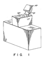
- FIG. 1 shows a conventional bar code reading device mounted on a check-out counter.
- a cashier or an operator sequentially takes the articles out of the basket, one at a time, turns the bar code printed on a label of the article to face reading window WP formed on the upper surface of the cabinet, so that the bar code reading device can read the bar code, and then places each article whose bar code has been read into another basket.
- the bar code reading device reads the bar code by emitting a light beam through reading window WP and receiving therethrough the light beam reflected from the article and transmitted to the bar code reading device.
- reading recognition lamp LP is lit and display unit DP displays the price of the article or the like obtained based on the article information corresponding to the bar code which has just been read. If no bar code is attached to the article, or if the bar code attached to the article cannot be read because of the presence of stains or smears, the article information concerning the article will be input into the bar code reading device by manually operating keyboard KP.
- An object of this invention is to provide a bar code reading device which can be installed in a small space and which the operator can operate in a natural posture.
- a bar code reading device which comprises a transparent liquid crystal display section; a transparent touch sensor section formed on the liquid crystal display section; a code reader for reading a bar code attached to an article by emitting a light beam through a window constituted by the liquid crystal display section and the touch sensor section and receiving therethrough the light beam reflected from the bar code of the article; and a control circuit for selectively setting one of a manual input mode and a code reading mode, driving the liquid crystal display section to display an image of a keyboard in the manual input mode and to erase the image of the keyboard in the code reading mode, and reading key-in data entered by touching portions of the touch sensor section with reference to the image of the keyboad in the manual input mode.
- the light beam used for reading the bar code attached to the article is transmitted via the liquid crystal display section and the touch sensor section.
- the manual input mode an image of the keyboard is displayed on the liquid crystal display section and the operation of the displayed keyboard is detected by the touch sensor section.
- Fig. 2 is a perspective view of the bar code reading device
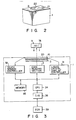
- Fig. 3 is a block diagram showing the circuit construction
- Fig. 4 is a plan view of a liquid crystal display panel
- Fig. 5 is a plan view of a touch panel.
- the bar code reading device of this embodiment includes main body 1, code reading section 3 disposed inside main body 1, reading window 2 made of glass and disposed in the surface area of main body 1, transparent liquid crystal display panel 10 mounted on reading window 2, and transparent touch sensor panel 20 disposed on panel 10.
- liquid crystal display panel 10 includes keyboard display area 10A, data display area 10B, and mode key display area 10C. The shape and size of the liquid crystal display panel 10 and touch sensor panel 20 are the same as those of reading window 2.
- Keyboard display area 10A is used to display an image of keyboard KB constituted by a plurality of input keys 12 arranged in a matrix configuration and having substantially the same function as conventional input keys
- data display area 10B serves to display an image of display unit 18 having substantially the same function as a conventional display unit
- mode key display area 10C serves to display images of mode keys 15 and 16 for specifying the manual input mode and the automatic reading mode, respectively
- Liquid crystal display panel 10 is controlled by means of liquid crystal display controller 31 disposed inside main body 1. At the time of interruption of display, a light beam emitted from code reading section (constituted by an optical scanning system and a reading circuit) 3 and a light beam reflected from article 7 can pass through liquid crystal display panel 10.
- code reading section constituted by an optical scanning system and a reading circuit
- Touch sensor panel 20 includes a plurality of touch sensor 21 which are assigned on a one-to-one basis to the keys - i.e. input keys 12 and mode keys 15 and 16 - displayed on liquid crystal display panel 10.
- the touch sensor assigned to this key is operated, thus enabling the data associated therewith to be entered.
- accidental touching of the touch sensors will cause data to be generated and entered.
- a light beam can pass through touch sensor panel 20 as in the case of liquid crystal display panel 10 and touch sensor panel 20 is controlled by means of touch sensor controller 32.
- the bar code reading device further includes CPU 34 and memory section 35 connected to touch sensor controller 32, code reading section 3, and liquid crystal display controller 31.
- Memory section 35 serves to store the control program for CPU 34 and input/output data of this CPU.
- CPU 34 controls the operations of touch sensor controller 32, code reading section 3, and liquid crystal display controller 31 according to the control program. Further, CPU 34 is connected to an external electronic cash register (ECR) via I/O interface 36.
- ECR electronic cash register
- Figs. 6 and 7 are flowcharts showing the operation of the bar coded reading device.
- each circuit element is initialized in step S10, and then it is checked in step S12 whether or not a bar code has been detected by code reading section 3.
- touch sensor controller 32, code reading section 3, and liquid crystal display controller 31 are driven: touch sensor controller 32 detects input data entered by operation of touch sensor 21, code reading section 3 scans article 7 by means of a light beam and detects the bar code on article 7 by way of the light beam reflected therefrom, and display controller 31 controls liquid crystal display panel 10 to display mode keys 15 and 16 and display unit 18.
- step S12 If it is determined in step S12 that a bar code has been detected, article information corresponding to the detected bar code is supplied to ECR 39 in step S18, and data supplied from ECR 39 is displayed on data display area 10B of liquid crystal display panel 10 in step S20. After this, step S12 is effected again.
- step S12 If on the other hands, it is determined in step S12 that no bar code has been detected by code reading section 3, it is checked in step S14 whether or not a key input operation has been detected by touch sensor controller 32. If no key input operation is detected, step S12 is effected again. In contrast, if a key input operation is detected, input data is processed in step S16.
- Fig. 7 shows the input data processing operation. If it is detected in step S100 that manual input mode key 15 has been operated, the operation of code reading section 3 is inhibited in step S102 and keyboard KB is displayed on keyboard display area 10A in step S104. Further, a manual input flag is set to "1" in step S106 and then step S108 is effected. If it is detected in step S120 that automatic reading mode key 16 has been operated, code reading section 3 is driven in step S122 and keyboard KB is erased in step S124. In this case, the manual input flag is set to "0" and then step S108 is effected. When keyboard KB has been operated, step S108 is effected.
- step S108 If it is detected in step S108 that the manual input flag is set at "1”, keyboard input data is read and processed in step S110, and then step S18 shown in Fig. 6 is effected. If, on the other hand, it is detected in step S108 that the manual input flag is set at "0", keyboard input data is cleared in step S128. After this, step S18 shown in Fig. 6 is effected.
- step S18 article information obtained in the key input processing is supplied to ECR 39 in the same manner as the article information of the bar code.
- step S20 ECR 39 supplies data based on the article information to CPU 34, via I/O interface 39, the data then being displayed in data display area 10B.
- keyboard input data to be processed in step S110 is not present, no article information can be obtained. In this case, no operation is effected in steps S18 and S20, and the following operation is effected.
- Code reading section 3 reads the bar code based on the incident light beam and determines article information corresponding to the bar code.
- the article information is stored in memory section 35 and then supplied from the bar code reading device to ECR 39.
- ECR 39 the article information is registered, and data representing the name and price of the article and the like obtained based on the article information is fed back to the bar code reading device and displayed as shown in Fig. 8.
- the mode which has been set is will remain unchanged until either mode key 15 or 16 is operated.
- a light beam passes an area of liquid crystal display panel 10 in the automatic reading mode, and keyboard KB is displayed on the area of liquid crystal display panel 10 and the operation of keyboard KB is detected by sensor panel 20 in the manual input mode.
- mode keys 15 and 16 and display unit 18 are displayed on liquid crystal display panel 10, the construction of the bar code reading device can be further simplified.
- the bar code reading 3evice is used for the cash register, but the application of this bar code reading device is not limited to this.
- it can also be used with reading window 2 set in an inclined or upright position to read the bar codes of packages carried on a conveyer belt.
- display unit 18 and mode keys 15 and 16 are displayed as picture images on liquid crystal display panel 10, but this invention is not limited to this.
- display unit DS and mode selection button MS can be provided separately from liquid crystal display panel 10.
- display unit DS and mode selection button MS are connected to CPU 34.
Landscapes
- Physics & Mathematics (AREA)
- Electromagnetism (AREA)
- Engineering & Computer Science (AREA)
- Health & Medical Sciences (AREA)
- General Health & Medical Sciences (AREA)
- Toxicology (AREA)
- Artificial Intelligence (AREA)
- Computer Vision & Pattern Recognition (AREA)
- General Physics & Mathematics (AREA)
- Theoretical Computer Science (AREA)
- Input From Keyboards Or The Like (AREA)
- Cash Registers Or Receiving Machines (AREA)
Applications Claiming Priority (2)
| Application Number | Priority Date | Filing Date | Title |
|---|---|---|---|
| JP152029/88 | 1988-06-20 | ||
| JP63152029A JPH01319882A (ja) | 1988-06-20 | 1988-06-20 | バーコード読取装置 |
Publications (2)
| Publication Number | Publication Date |
|---|---|
| EP0347814A2 true EP0347814A2 (de) | 1989-12-27 |
| EP0347814A3 EP0347814A3 (de) | 1990-07-11 |
Family
ID=15531505
Family Applications (1)
| Application Number | Title | Priority Date | Filing Date |
|---|---|---|---|
| EP89111137A Ceased EP0347814A3 (de) | 1988-06-20 | 1989-06-19 | Strichkode-Abtastvorrichtung |
Country Status (3)
| Country | Link |
|---|---|
| US (1) | US5021640A (de) |
| EP (1) | EP0347814A3 (de) |
| JP (1) | JPH01319882A (de) |
Cited By (1)
| Publication number | Priority date | Publication date | Assignee | Title |
|---|---|---|---|---|
| EP0490605A1 (de) * | 1990-12-10 | 1992-06-17 | Ncr International Inc. | Optischer Abtastapparat zum Lesen von verschlüsselten Symbolen |
Families Citing this family (21)
| Publication number | Priority date | Publication date | Assignee | Title |
|---|---|---|---|---|
| US5316107A (en) * | 1989-06-20 | 1994-05-31 | Siemens Nixdorf Informationssysteme Ag | Device for checking out goods |
| US5196686A (en) * | 1989-11-22 | 1993-03-23 | Ncr Corporation | Checkout system with inlaid checkout counter keypad |
| JPH05181885A (ja) * | 1991-03-13 | 1993-07-23 | Hitachi Ltd | 自動取引装置およびこれを用いる取引データ入力システム |
| US5211263A (en) * | 1992-01-21 | 1993-05-18 | In-Store Products Limited | Store check-out station |
| CA2097360A1 (en) * | 1992-06-03 | 1993-12-04 | Paul Dvorkis | Optical readers |
| US5536930A (en) * | 1992-06-03 | 1996-07-16 | Symbol Technologies, Inc. | Apparatus and method for sensing positional orientations of a portable terminal |
| US5334821A (en) * | 1992-07-16 | 1994-08-02 | Telxon Corporation | Portable point of sale terminal |
| US5499108C1 (en) * | 1992-07-29 | 2001-01-16 | Primax Electronics Ltd | Document-driven scanning input device communicating with a computer |
| GB2282906B (en) | 1993-10-13 | 1996-11-06 | Dataquill Ltd | Data enty systems |
| US5581064A (en) * | 1994-11-01 | 1996-12-03 | Pennsylvania Food Merchants Association | Automated coupon processing system employing coupon with identifying code and chosen second identifying code uniquely identifying the coupon |
| JPH08242417A (ja) * | 1995-03-01 | 1996-09-17 | Olympus Optical Co Ltd | 情報再生システム及び情報記録媒体 |
| JP2002508094A (ja) * | 1996-06-27 | 2002-03-12 | マイケル ジェイ ウーレ | 高速多重化シリアル接続を使用しかつi/oデバイスを組み込んだキーボード |
| US5952998A (en) * | 1997-01-15 | 1999-09-14 | Compaq Computer Corporation | Transparent touchpad with flat panel display for personal computers |
| US6972945B1 (en) | 1997-10-17 | 2005-12-06 | Gateway Inc. | Modular computer device and computer keyboard for modular device |
| WO1999050783A1 (en) | 1998-03-31 | 1999-10-07 | Logic Controls, Inc. | Integrated keyboard input device |
| US6540144B1 (en) * | 1999-07-16 | 2003-04-01 | Metrologic Instruments, Inc. | Techniques for interfacing a bar code scanner to a PC using a keyboard retransmit protocol |
| US6536666B1 (en) * | 1999-07-16 | 2003-03-25 | Metrologic Instruments, Inc. | Techniques for interfacing a bar code scanner to a PC using a message-based and/or character-based keyboard inhibit |
| US7030860B1 (en) * | 1999-10-08 | 2006-04-18 | Synaptics Incorporated | Flexible transparent touch sensing system for electronic devices |
| US7081887B2 (en) * | 2002-12-19 | 2006-07-25 | Intel Corporation | Method and apparatus for positioning a software keyboard |
| US8130197B2 (en) * | 2005-03-15 | 2012-03-06 | Ergowerx. LLC | Floating keyboard |
| CN102681669B (zh) * | 2011-02-22 | 2015-12-16 | 梁晨 | 一种双区键盘及其输入方法 |
Family Cites Families (7)
| Publication number | Priority date | Publication date | Assignee | Title |
|---|---|---|---|---|
| US4078257A (en) * | 1976-08-23 | 1978-03-07 | Hewlett-Packard Company | Calculator apparatus with electronically alterable key symbols |
| US4274093A (en) * | 1979-02-26 | 1981-06-16 | Technicon Instruments Corporation | Keyboard-display combination |
| JPS5743272A (en) * | 1980-08-28 | 1982-03-11 | Sharp Corp | Optical reader |
| JPS588381A (ja) * | 1981-07-07 | 1983-01-18 | Nippon Denso Co Ltd | バ−コ−ド読取装置 |
| JPS59191675A (ja) * | 1983-04-15 | 1984-10-30 | Casio Comput Co Ltd | 光学的読取装置 |
| JPS62284419A (ja) * | 1986-05-31 | 1987-12-10 | Toshiba Corp | 入力装置 |
| JPS63127324A (ja) * | 1986-11-18 | 1988-05-31 | Hitachi Ltd | タツチパネル入力装置 |
-
1988
- 1988-06-20 JP JP63152029A patent/JPH01319882A/ja active Pending
-
1989
- 1989-06-15 US US07/366,700 patent/US5021640A/en not_active Expired - Fee Related
- 1989-06-19 EP EP89111137A patent/EP0347814A3/de not_active Ceased
Cited By (1)
| Publication number | Priority date | Publication date | Assignee | Title |
|---|---|---|---|---|
| EP0490605A1 (de) * | 1990-12-10 | 1992-06-17 | Ncr International Inc. | Optischer Abtastapparat zum Lesen von verschlüsselten Symbolen |
Also Published As
| Publication number | Publication date |
|---|---|
| EP0347814A3 (de) | 1990-07-11 |
| US5021640A (en) | 1991-06-04 |
| JPH01319882A (ja) | 1989-12-26 |
Similar Documents
| Publication | Publication Date | Title |
|---|---|---|
| US5021640A (en) | Apparatus capable of being operated as both a bar code reading device and a manual keyboard | |
| US5315097A (en) | Method and apparatus for operating a triggerless hand-held optical scanner | |
| US5859414A (en) | Interactive customer information terminal | |
| US5662190A (en) | Self-scanning checkout apparatus having article passage detecting sensor | |
| US5406063A (en) | Hand-held data scanner having adjustable keyboard panel | |
| US5107100A (en) | Portable scanner with on-board keyboard, display, transceiver and printer | |
| US5149947A (en) | Portable checkout system | |
| US5155345A (en) | Data read device | |
| EP0689174A2 (de) | Waren-Registriervorrichtung | |
| US20070138271A1 (en) | Commodity sales registration processing system and commodity information registering apparatus | |
| JP2005251164A (ja) | 採集装置 | |
| EP0420643B1 (de) | Verkaufsstellendatenterminal | |
| JPH09132146A (ja) | 自動スキャンカート | |
| JP2001052105A (ja) | 複合コード読取装置 | |
| EP0853290B1 (de) | Verfahren zum Verarbeiten von Produkten bei einem Kassenterminalsystem | |
| JP2000346700A (ja) | バーコード読取装置、計量器及び計量方法 | |
| JPH07152961A (ja) | Pos装置 | |
| KR0124369B1 (ko) | 자동판매기 | |
| JP3669630B2 (ja) | スキャナ装置および商品コードの入力方法 | |
| JPH06314350A (ja) | バーコードスキャナ | |
| JPS63149791A (ja) | 登録機能付き買物籠 | |
| JP2829959B2 (ja) | 情報送信装置 | |
| JPS6339098A (ja) | ハンデイ型カ−ド読取装置 | |
| JP2566839B2 (ja) | 商品販売データ処理装置 | |
| JPH0373030B2 (de) |
Legal Events
| Date | Code | Title | Description |
|---|---|---|---|
| PUAI | Public reference made under article 153(3) epc to a published international application that has entered the european phase |
Free format text: ORIGINAL CODE: 0009012 |
|
| 17P | Request for examination filed |
Effective date: 19890619 |
|
| AK | Designated contracting states |
Kind code of ref document: A2 Designated state(s): DE FR GB |
|
| PUAL | Search report despatched |
Free format text: ORIGINAL CODE: 0009013 |
|
| AK | Designated contracting states |
Kind code of ref document: A3 Designated state(s): DE FR GB |
|
| 17Q | First examination report despatched |
Effective date: 19921113 |
|
| STAA | Information on the status of an ep patent application or granted ep patent |
Free format text: STATUS: THE APPLICATION HAS BEEN REFUSED |
|
| 18R | Application refused |
Effective date: 19930506 |