EP0347775B1 - Tasteninstrument - Google Patents
Tasteninstrument Download PDFInfo
- Publication number
- EP0347775B1 EP0347775B1 EP89110992A EP89110992A EP0347775B1 EP 0347775 B1 EP0347775 B1 EP 0347775B1 EP 89110992 A EP89110992 A EP 89110992A EP 89110992 A EP89110992 A EP 89110992A EP 0347775 B1 EP0347775 B1 EP 0347775B1
- Authority
- EP
- European Patent Office
- Prior art keywords
- sound
- resonance
- speaker
- cabinet
- keyboard
- Prior art date
- Legal status (The legal status is an assumption and is not a legal conclusion. Google has not performed a legal analysis and makes no representation as to the accuracy of the status listed.)
- Expired - Lifetime
Links
- 239000000463 material Substances 0.000 claims description 5
- 238000013016 damping Methods 0.000 claims description 2
- 230000003247 decreasing effect Effects 0.000 description 13
- 230000005855 radiation Effects 0.000 description 10
- 238000013461 design Methods 0.000 description 8
- 238000010586 diagram Methods 0.000 description 7
- 239000007787 solid Substances 0.000 description 5
- 230000002093 peripheral effect Effects 0.000 description 4
- 230000002411 adverse Effects 0.000 description 2
- 230000005540 biological transmission Effects 0.000 description 2
- 230000015556 catabolic process Effects 0.000 description 2
- 238000006731 degradation reaction Methods 0.000 description 2
- 238000001514 detection method Methods 0.000 description 2
- 230000001747 exhibiting effect Effects 0.000 description 2
- 238000000034 method Methods 0.000 description 2
- 238000005192 partition Methods 0.000 description 2
- 239000004020 conductor Substances 0.000 description 1
- 238000012937 correction Methods 0.000 description 1
- 230000000994 depressogenic effect Effects 0.000 description 1
- 230000004069 differentiation Effects 0.000 description 1
- 230000000694 effects Effects 0.000 description 1
- 239000004744 fabric Substances 0.000 description 1
- 230000004907 flux Effects 0.000 description 1
- 239000011491 glass wool Substances 0.000 description 1
- 230000010354 integration Effects 0.000 description 1
- 230000004807 localization Effects 0.000 description 1
- 239000007769 metal material Substances 0.000 description 1
- 238000012986 modification Methods 0.000 description 1
- 230000004048 modification Effects 0.000 description 1
- 238000012544 monitoring process Methods 0.000 description 1
- 239000004033 plastic Substances 0.000 description 1
- 238000003908 quality control method Methods 0.000 description 1
- 230000001603 reducing effect Effects 0.000 description 1
- 230000003014 reinforcing effect Effects 0.000 description 1
- 230000033764 rhythmic process Effects 0.000 description 1
- 239000000523 sample Substances 0.000 description 1
- 230000001052 transient effect Effects 0.000 description 1
- 239000003190 viscoelastic substance Substances 0.000 description 1
- 239000002023 wood Substances 0.000 description 1
- 239000002759 woven fabric Substances 0.000 description 1
Images


Classifications
-
- G—PHYSICS
- G10—MUSICAL INSTRUMENTS; ACOUSTICS
- G10H—ELECTROPHONIC MUSICAL INSTRUMENTS; INSTRUMENTS IN WHICH THE TONES ARE GENERATED BY ELECTROMECHANICAL MEANS OR ELECTRONIC GENERATORS, OR IN WHICH THE TONES ARE SYNTHESISED FROM A DATA STORE
- G10H1/00—Details of electrophonic musical instruments
- G10H1/0091—Means for obtaining special acoustic effects
-
- G—PHYSICS
- G10—MUSICAL INSTRUMENTS; ACOUSTICS
- G10H—ELECTROPHONIC MUSICAL INSTRUMENTS; INSTRUMENTS IN WHICH THE TONES ARE GENERATED BY ELECTROMECHANICAL MEANS OR ELECTRONIC GENERATORS, OR IN WHICH THE TONES ARE SYNTHESISED FROM A DATA STORE
- G10H1/00—Details of electrophonic musical instruments
- G10H1/32—Constructional details
-
- G—PHYSICS
- G10—MUSICAL INSTRUMENTS; ACOUSTICS
- G10H—ELECTROPHONIC MUSICAL INSTRUMENTS; INSTRUMENTS IN WHICH THE TONES ARE GENERATED BY ELECTROMECHANICAL MEANS OR ELECTRONIC GENERATORS, OR IN WHICH THE TONES ARE SYNTHESISED FROM A DATA STORE
- G10H2210/00—Aspects or methods of musical processing having intrinsic musical character, i.e. involving musical theory or musical parameters or relying on musical knowledge, as applied in electrophonic musical tools or instruments
- G10H2210/155—Musical effects
- G10H2210/265—Acoustic effect simulation, i.e. volume, spatial, resonance or reverberation effects added to a musical sound, usually by appropriate filtering or delays
- G10H2210/271—Sympathetic resonance, i.e. adding harmonics simulating sympathetic resonance from other strings
- G10H2210/275—Helmholtz resonance effect, i.e. using, exciting or emulating air resonance in a cavity
-
- Y—GENERAL TAGGING OF NEW TECHNOLOGICAL DEVELOPMENTS; GENERAL TAGGING OF CROSS-SECTIONAL TECHNOLOGIES SPANNING OVER SEVERAL SECTIONS OF THE IPC; TECHNICAL SUBJECTS COVERED BY FORMER USPC CROSS-REFERENCE ART COLLECTIONS [XRACs] AND DIGESTS
- Y10—TECHNICAL SUBJECTS COVERED BY FORMER USPC
- Y10S—TECHNICAL SUBJECTS COVERED BY FORMER USPC CROSS-REFERENCE ART COLLECTIONS [XRACs] AND DIGESTS
- Y10S84/00—Music
- Y10S84/01—Plural speakers
Definitions
- the present invention relates to a keyboard instrument incorporating a sound system for generating musical tones and, more particularly, to an electric or electronic keyboard instrument designed to reduce a sound system in size and improve sound quality or frequency characteristics.
- an electronic musical instrument comprising a keyboard, a sound source for generating a musical tone signal on the basis of a key operation of said keyboard, and a sound system for converting the musical tone signal into a sound and radiating the sound
- said sound system comprises a cabinet, an electroacoustic transducer having a vibrating body arranged on an outer wall of said cabinet for directly radiating a sound from one surface of the vibrating body, and a driving means comprising an amplifier for driving said transducer.
- two high-frequency speakers are mounted on the console or body member of said instrument in such a manner that the sound waves emanating therefrom will travel directly to the ear location of the instrument player.
- Medium-frequency loudspeakers are mounted within the bottom portion of the body member and are arranged in such a manner that the sound waves emanating therefrom will travel in a substantially perpendicular or vertical direction towards the floor surface to be heard indirectly by the player of the instrument.
- a speaker unit is arranged at a rear portion of a keyboard section. These speaker units are fixed so that their sound radiating directions (axial direction of a diaphragm) are directed to various directions.
- a slit tone escape
- the diaphragm of the speaker is arranged to oppose the slit in a substantially horizontal state.
- a speaker is arranged to generate musical sounds toward the rear portion of the main body case. That is, a tone escape is arranged to be open to a side opposite to a performer.
- an 88-key piano has a lowest bass tone (A0) of 27.5 Hz, and the frequency of a fundamental wave of a bass drum during automatic rhythm performance is about 30 Hz.
- A0 bass tone
- these ultra low bass tones pose no problem to the performer in monitoring (grasping) a normal performance, even though a fundamental wave itself is not produced enough. This is because if harmonic waves are reproduced, the bass tones are compensated in audible levels.
- the bass drum if a fundamental wave of about 30 Hz is slightly output at a level exceeding an audible sound pressure limit, and a harmonic overtone of 50 to 60 Hz is sufficiently output, the generated tone is felt as a heavy bass tone by the performer.
- a sound system having of lowest reproduction frequency of about 70 Hz or more is used, generated tones become less rich in low frequency region, thus exhibiting a great difference in sound quality.
- a sound system incorporated in conventional keyboard instruments comprises a closed or phase-inversion (bass-reflex) type speaker system and a power amplifier, having a substantially zero output impedance, for constant-voltage driving the speaker system.
- the lowest reproduction frequency of the speaker system is mainly determined by the volume of a cabinet (e.g., a main body case) and the characteristics (f0, Q0, and the like) of a speaker unit used in the system. That is, in the conventional keyboard instruments, if musical tones having lower frequencies are to be produced, a cabinet having a larger volume is required, resulting in considerable limitation in design. In addition, performance may be interfered depending on an arrangement of the cabinet, and other problems are posed in terms of operation.
- Fig. 16 shows an outer appearance of a keyboard instrument designed by integrally forming a rear frame 21 and a cabinet 7. Referring to Fig. 16, reference symbols 9a and 9b respectively denote bass-reflex ports (resonance ports).
- the present invention has been made in consideration of the problems posed in the above-described conventional keyboard instruments.
- a second object of the invention is to provide a keyboard instrument which allows a performer to directly and clearly grasp performance sounds and which has a low profile and allows peripheral units to be arranged on the upper surface of an instrument case.
- a keyboard instrument is as claimed in claim 1.
- Figs. 1 and 2 show a keyboard instrument according to a first embodiment of the present invention.
- an electronic keyboard instrument comprises a box type main body case 111.
- a keyboard 113 and a speaker assembly 115 are arranged in the main body case 111.
- the keyboard 113 is arranged on the front side of the main body case 111 so as to be vertically swingable.
- a tone escape 131 is open to an upper portion on the rear side of the keyboard 113.
- the keyboard 113 is constituted by a plurality of aligned keys 121.
- the rear end of each key 121 is swingably supported by a pin 122 as a fulcrum. Switches for detecting depression of these keys 121 and switches for detecting depression strength are arranged around the keys 121.
- a speaker unit 115A for bass tones and a speaker unit 115B for treble tones are respectively arranged on the rear side of the keyboard 113 of the main body case 111. These speaker units 115A and 115B are respectively arranged upright in the main body case 111 so as to form predetermined angles with respect to the horizontal plane, e.g., the lower surface of the main body case 111.
- Reference numeral 123 denotes a bracket for fixing the speaker units 115A and 115B.
- the middle-frequency or low-frequency speaker unit (squawker or woofer) 115A has a larger diameter than the high-frequency speaker unit (tweeter) 115B.
- the inclination of the speaker unit 115A is smaller than that of the speaker unit 115B (see Fig. 1).
- the tweeter 115B has a diameter of, for example, 12 cm, whereas the squawker 115A has diameter of, for example, 20 cm.
- Both the speaker units 115A and 115B are arranged upright to generate musical tones forward.
- the axis of a diaphragm of the small-diameter speaker unit 115B is directed to the tone escape 131.
- the axis of a diaphragm of the large-diameter speaker unit 115A is directed to the case located slightly above the tone escape 131.
- the tone escape 131 is formed at the front surface of the main body case 111 located at a position above the rear side of the keyboard 113.
- vibrations of the diaphragms of the speaker units 115A and 115B are transmitted to a performer through the tone escape 131.
- the performer can directly and clearly discriminate sound quality of performance tones, degradation in sound quality, and the like.
- the upper surface of the main body case 111 can be formed to be flat, and a slit such as the tone escape 131 need not be formed in the upper surface. Therefore, a peripheral unit such as an automatic performance unit and the like can be placed on the upper surface. In addition, a music desk can be formed on the upper desk as with the case of the conventional instruments.
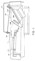
- Fig. 3 shows an outer appearance of a keyboard instrument according to a second embodiment of the present invention.
- This keyboard instrument employs a speaker system with a resonance port as a speaker system constituting a sound system.
- This speaker system comprises Helmholtz resonators like a conventional bass-reflex type speaker system, and is similar in shape to the bass-reflex type speaker system.
- the volume of the cavity of each Helmholtz resonator of this speaker system is greatly decreased to several liters which is very small in comparison with a volume of 20 to 30 liters of the conventional bass-reflex type speaker system.
- each resonance port is elongated to set the resonance frequency of the resonator to be 50 to 60 Hz which is equal to or lower than that of the conventional bass-reflex type speaker system.
- Fig. 4 is a sectional view taken along a line A - A in Fig. 3.
- Fig. 5 is a perspective view showing a state wherein some exterior components omitted.
- a shelf plate 1 is held by two vertical leg portions 2a and 2b at a predetermined height.
- a keyboard 3 speaker mounting bases 5a and 5b for left and right channels, on which speaker units 4a and 4b are mounted, and electric circuits (not shown) including a sound source and amplifiers for driving the speakers of the respective channels are mounted on the shelf plate 1.
- openings 6a and 6b are formed in the shelf plate 1, and a cabinet 7 is formed under the shelf plate 1. Cavities and resonance ports are formed between the shelf plate 1 and the cabinet 7.
- opening ports 9a and 9b are formed in a bottom plate 8 of the cabinet 7, and the interior of the cabinet 7 is partitioned by an intermediate plate 10 and partition plates 11a to 11d.
- Portions partitioned by the opening ports 9a and 9b and the partition plates 11a to 11d, which respectively communicate with the ports 9a and 9b, constitute resonance ports of the Helmholtz resonators when the cabinet 7 is mounted on the shelf plate 1 and the upper portion of the cabinet 7 is closed.
- Spaces other than the resonance ports constitute cavities when the cabinet 7 is mounted on the shelf plate 1 and the upper portion of the cabinet 7 is closed, and is divided into two cavities for the left and right speaker systems by the intermediate plate 10.
- these spaces respectively communicate with spaces formed on the rear sides of the left and right speaker mounting bases 5a and 5b through the openings 6a and 6b, and cavities of the Helmholtz resonators are formed by the spaces of the cabinet 7 and the spaces of the speaker mounting bases 5a and 5b.
- the intermediate plate 10 is attached to be slightly shifted from the center toward the right side, so that the volumes of the cavities for the left and right channel speaker systems are respectively set to be about 5.5 and 4.5 liters.
- the resonance frequencies of the left and right Helmholtz resonators are set to be different from each other, i.e., 50 and 60 Hz, respectively.
- Felts 12a and 12b are bonded to the bottom plate 8 of the cabinet 7.
- the height of the cabinet 7 is as 1/10 small as its width, the above space portion strongly exhibits characteristics as a duct. If the wall enclosing this space consists of a rigid material such as a wood, plastic, or metal material, duct resonance tones having wavelengths corresponding to 1/2, 1, ...
- the felts 12a and 12b are bonded to prevent the duct resonance.
- other materials having air-permeability and acoustic resistance e.g., a sponge, an unwoven fabric, and a woven fabric may be used as such a duct resonance preventing means.
- the duct resonance preventing means may be constituted by a material having flexibility and viscoelasticity, e.g., rubber. Such flexible, viscoelastic material exhibits a pressure reducing effect substantially equivalent to the air-permeability of the felt and the like due to its flexibility, and serves as a resistor for consuming energy upon flexing due to its viscoelasticity.
- the cabinet 7 is reinforced by mounting triangular-prism-like reinforcing members 13a to 13f at several positions.
- slit-like opening groups 15a and 15b are formed in a front panel 14 of the keyboard instrument. Direct radiation tones from the speaker units 4a and 4b obliquely arranged in the instrument are output to the outside through the opening groups 15a and 15b, respectively. With this arrangement, openings for the direct radiation tones need not be formed in a top plate 16, and hence musical scores, ornaments, and the like can be placed on the top plate 16 without worrying about sound quality.
- a frame 21 is formed between the leg portions 2a and 2b below the cabinet 7 so as to reinforce a structure constituted by the shelf plate 1, the leg portions 2a and 2b, and the like.
- Fig. 7 is a circuit diagram for explaining a fundamental arrangement of an acoustic unit (sound system) incorporated in the keyboard instrument shown in Fig. 3.
- This acoustic unit includes the speaker system with the resonance port and an amplifier for driving the speaker system.
- Figs. 3 and 6 show an arrangement of each speaker system mounted in the instrument.
- a hole is formed in the front surface of a cabinet 7, and a dynamic type electro-acoustic transducer (speaker unit) 4 (4a, 4b) is mounted in the hole.
- An resonance port 18 which has a sound path 17 opening to outword of the cabinet 7 through a opening port portion 9 (9a, 9b) is arranged below the transducer 4.
- the resonance port 18 and the cabinet 7 form a Helmholtz resonator. In this Helmholtz resonator, an air resonance phenomenon occurs due to an air spring in the cabinet 7 as a closed cavity and an air mass in the sound path 17.
- the driver circuit 50 comprises a frequency characteristics compensation circuit 51, negative impedance driver 52 and the like.
- the negative impedance driver 52 comprises a amplifier 53, resistor R S , and feedback circuit 54.
- an output from the amplifier 53 having a gain A is supplied to the speaker unit 4 of the speaker system as a load Z L .
- a current I L flowing through the speaker unit 4 is detected by the resistor R S , and the detected current is positively fed back to the amplifier 53 through the feedback circuit 54 having a transmission gain ⁇ .
- Fig. 8 shows an arrangement of an electric equivalent circuit of the portion comprising the speaker system shown in Fig. 7.
- a parallel resonance circuit Z1 is formed by the equivalent motional impedances which are caused by the motion of the unit vibration system comprising the diaphragm 41 of the speaker unit 4.
- reference symbol r o denotes an equivalent resistance of the vibration system
- S o an equivalent stiffness of the vibration system
- m o an equivalent mass of the vibration system.
- a series resonance circuit Z2 is formed by an equivalent motional impedance of a Helmholtz resonator constituted by the resonance port and the cavity.
- reference symbol r c denotes an equivalent resistance of the cavity of the resonator
- S c an equivalent stiffness of the cavity
- r p an equivalent resistance of the resonance port
- m p an equivalent mass of the resonance port.
- reference symbol A denotes a force coefficient.
- B the magnetic flux density in a magnetic gap
- l v the total length of a voice coil conductor.
- reference symbol Z V denotes an internal impedance (non-motional impedance) of the speaker unit 4.
- the impedance Z V mainly comprises a resistance R V of the voice coil, and includes a small inductance.
- the speaker unit 4 When a drive signal is supplied from the driver circuit 50 having a negative impedance drive function to the speaker unit 4, the speaker unit 4 electro-mechanically converts this signal to reciprocate its diaphragm 41 forward and backward (to the left and right in Fig. 7).
- the diaphragm 41 mechano-acoustically converts the reciprocal motion. Since the driver circuit 50 has the negative impedance drive function, the internal impedance of the speaker unit 4 is equivalently reduced (ideally invalidated). Therefore, the speaker unit 4 drives the diaphragm 41 while faithfully responding to the drive signal input to the driver circuit 50, and independently supplies drive energy to the Helmholtz resonator constituted by the resonance port 18 and the cabinet 7. In this case, the front surface side (the right surface side in Fig.
- the diaphragm 41 serves as a direct radiator portion for directly radiating acoustic wave to the outward, and the rear surface side (the left surface side in Fig. 7) of the diaphragm 41 serves as a resonator driver portion for driving the Helmholtz resonator constituted by the resonance port 18 and the cabinet 7.
- an acoustic wave is directly radiated from the diaphragm 41, and air in the cabinet 7 is resonated, so that an acoustic wave having a sufficient sound pressure is resonantly radiated from the resonance radiation portion (the opening portion 9 of the resonance port 18), as indicated by an arrow b in the Figure.
- equivalent resistances r c and r p of a resonance port 18 and a cavity are converted into a resistance series-connected to motional impedances S c and m p in Fig. 8, and coefficients assigned to the respective elements are omitted.
- the parallel resonance circuit Z1 has a Q value of 0, and can no longer serve as a resonance circuit. More specifically, this speaker unit 4 loses the concept of a lowest resonance frequency which is present in a state wherein the speaker unit 4 is merely mounted on the Helmholtz resonator. In the following description, the lowest resonance frequency f0 or equivalent of the speaker unit 4 merely means the essentially invalidated concept. In this manner, since the unit vibration system (parallel resonance circuit) Z1 does not essentially serve as a resonance circuit, the resonance system in this acoustic apparatus is only the Helmholtz resonance system (series resonance circuit) Z2.
- the speaker unit 4 Since the speaker unit 4 does not essentially serve as the resonance circuit, it linearly responds to a drive signal input in real time, and faithfully electro-mechanically converts an electrical input signal (drive signal E0), thus displacing the diaphragm 41 without transient responce. That is, a perfect damped state (so-called "speaker dead” state) is achieved.
- the output sound pressure-frequency characteristics around the lowest resonance frequency f0 or equivalent of this speaker in this state are 6 dB/oct. Contrary to this, characteristics of a normal voltage drive state are 12 dB/oct.
- the series resonance circuit Z2 formed by the equivalent motional impedance of the Helmholtz resonator is connected to the drive signal source E0 at a zero impedance.
- the circuit Z2 no longer has a mutual dependency with the parallel resonance circuit Z1.
- the parallel resonance circuit Z1 and the series resonance circuit Z2 are present independently of each other. Therefore, the volume (in inverse proportion to S c ) of the cabinet 7, and the shape and dimension (in proportion to m p ) of the resonance port 18 do not adversely influence the direct radiation characteristics of the speaker unit 4.
- the resonance frequency and the Q value of the Helmholtz resonator are not influenced by the equivalent motional impedance of the speaker unit 4.
- the characteristic values (f op , Q op ) of the Helmholtz resonator and the characteristic values (f o , Q o ) of the speaker unit 4 can be independently set.
- the series resistance of the series resonance circuit Z2 is only r c + r p , and these resistances are sufficiently small values, as described above.
- the Q value of the series resonance circuit Z2, i.e., the Helmholtz resonator can be set to be sufficiently high.
- the diaphragm 41 contituting the unit vibration system is displaced according to a drive signal input E0, and is not influenced by an external force, in particular, an air counteraction caused by the equivalent stiffness S c of the cabinet.
- the diaphragm 41 equivalently serves as a wall when viewed from the cabinet side, and the presence of the speaker unit 4 when viewed from the Helmholtz resonator is invalidated. Therefore, the resonance frequency f op and the Q value Q op of the Helmholtz resonator do not depend on the non-motional impedance of the speaker unit 4.
- the Helmholtz resonance system is present as a virtual speaker which performs acoustic radiation quite independently of the unit vibration system.
- the virtual speaker is realized by a small diameter corresponding to the port diameter, it corresponds to one having a considerably large diameter as an actual speaker in view of its bass sound reproduction power.
- the system and apparatus of the present invention described above will be compared with a conventional system wherein a bass-reflex speaker system is driven by an ordinary power amplifier.
- a plurality of resonance systems i.e., the unit vibration system Z1 and the Helmholtz resonance system Z2, are present, and the resonance frequencies and the Q values of the resonance systems closely depend on each other. For example, if the resonance port is elongated or its diameter is reduced (m p is increased) to lower the resonance frequency of the Helmholtz resonance system Z2, the Q value of the unit vibration system Z1 is increased and the Q value of the Helmholtz resonance system Z2 is decreased.
- the Q value and the resonance frequency of the unit vibration system Z1 are increased, and the Q value of the Helmholtz resonance system Z2 is further decreased even if the resonance frequency of the Helmholtz resonance system Z2 is kept constant by elongating the port or decreasing its diameter. More specifically, since the output sound pressure-frequency characteristics of the speaker system are closely related to the volume of the cabinet and the dimensions of the port, a high-grade design technique is required to match them. Thus, it is generally not considered that a cabinet (or system) can easily be made compact in size without impairing the frequency characteristics of an output sound pressure, in particular, a bass range characteristics.
- the relationship between the frequency lower than the resonance frequency and a resonance acoustic radiation power in the Helmholtz resonance system Z2 is decreased at a rate of 12 dB/oct with respect to a decrease in frequency when viewed from the sound pressure level.
- the resonance frequency is set to be extremely lower than that of the basic concept of the bass-reflex speaker system, correction by increasing/decreasing an input signal level is very difficult to achieve.
- adverse influences on sound quality caused by the high Q value and the adrupt change in phase of the unit vibration system around the lowest resonance frequency cannot be eliminated.
- the speaker system utilizing Helmholtz resonance is driven by a negative impedance, the characteristics, dimensions, and the like of the unit vibration system and the Helmholtz resonance system can be independently set.
- the resonance frequency of the Helmholtz resonance system is set to be low, the large Q value and the high bass sound reproduction power can be maintained, and the resonator drive power of the unit vibration system can be increased (6 dB/oct). Therefore, nonuniformity of the frequency characteristics can be advantageously corrected by increasing/decreasing an input signal level like in normal sound quality control. For this reason, a cabinet can be rendered compact and speaker system can be made compact in size without impairing a frequency characteristics and a sound quality.
- the resonance frequencies and the Q values of the respective resonance systems may be set in a relatively optional manner when the driver circuit of this embodiment is used, the sound quality can be improved or the acoustic reproduction range, in particular, a bass sound range, can be easily expanded by driving an existing speaker system, as compared with the case wherein the speaker system is driven by a conventional constant-voltage driving system.
- Z V - Z0 > 0 may be allowed if -Z0 ⁇ 0.
- Figs. 11(a), 11(b), and 11(c) are graphs simulating the electric characteristics of the acoustic unit in Fig. 7 using the speaker system with the resonance port and a driver 50.
- the nominal impedance of a speaker unit 4 is set to be 8 ⁇ ; an AC input voltage e of a negative impedance generator 52 of the driver 50, 1 V; and an output impedance Z0, - 7 ⁇ .
- a solid curve a represents the frequency characteristic of an impedance Z L of the speaker system with the resonance port; a broken curve b , the frequency characteristic of an impedance due to an equivalent inductance A2/S o of the speaker unit 4; a broken curve c , the frequency characteristic of an impedance due to an equivalent capacitance m o /A2 of the speaker unit 4; a broken curve d , the frequency characteristic of an impedance due to an equivalent inductance A2/S c of the cabinet 7; a broken curve e , the frequency characteristic of an impedance due to an equivalent capacitance m p /A2 of the cabinet 7; and an alternate long and short dashed curve f , the frequency characteristic of an impedance of a unit resonance system Z1.
- the resonance frequency of the unit resonance system is set to be a value corresponding to the intersection point between the broken curves b and c , i.e., about 35 Hz
- the resonance frequency of a port resonance system is set to be a value corresponding to an intersection point between the broken curves d and e , i.e., about 40 Hz.
- a solid curve g represents an output terminal voltage V of the negative impedance generator 52; a broken curve h , the output sound pressure characteristic of a resonance radiation sound from the port resonance system; a broken curve i , the output sound pressure characteristic of a direct radiation sound from the unit resonance system; and a solid curve j , the synthetic output sound pressure characteristic as the speaker system obtained by mixing the broken curves h and i .
- Fig. 11(c) shows a case wherein a flat output sound pressure characteristic can be obtained at frequencies of 50 Hz or more as indicated by a solid curve j' by increasing/decreasing the input voltage e of the negative impedance generator 52 by using a frequency characteristic compensation circuit 51 of the driver 50 in accordance with a frequency and compensating the output voltage from the generator 52 as indicated by a solid curve g' .
- a broken curve k represents the output power (Watt) characteristic of an amplifier 53 (i.e., the negative impedance generator 52) when the output sound pressure characteristic is to be made flat.
- the port resonance frequencies of the speaker systems in the acoustic units of left and right channels are set to be different, i.e., 50 and 60 Hz, respectively.
- a synthetic frequency characteristic of the left and right speaker systems is shaped like as a sound pressure characteristic having a peak at 50 Hz, which is obtained from the resonance port of the left speaker, is added to an output sound pressure characteristic exhibiting a flat characteristic at frequencies of 60 Hz or more, which is obtained from the right speaker system.
- the uniform reproduction range can be widened toward the low-frequency side. If the characteristics of the frequency characteristic compensation circuit 51 are properly set, the low-frequency side of the uniform reproduction range can be widened to 50 Hz by using only the right channel.
- the output voltage of the amplifier 53 must be increased near the port resonance frequency, as indicated by the broken curve k in Fig. 11(c).
- the output power of the amplifier 53 in order to widen the low-frequency side of the uniform reproduction frequency by 10 Hz, the output power of the amplifier 53 must be increased by 6 dB (four times).
- the capacity of the amplifier 53 must be determined in terms of continuous rating in consideration of a case wherein keys are kept depressed. If the nominal output is assumed to be equal, the above-described system requires a power amplifier having an output several times larger than that of an audio amplifier whose output can be determined in terms of an intermittent or instant maximum output.
- the resonance frequency of the left port is set to be 50 Hz which is lower than that of the right port by 10 Hz.
- Output sound pressures at frequencies around 50 Hz are mainly radiated from the resonance port of the left speaker system so as to reduce the load of the right driver 50.
- sounds at around 60 Hz are mainly radiated from the resonance port of the right speaker system so as to reduce the load of the left driver 50.
- Fig. 12 shows the basic arrangement of a negative impedance generator 52 for driving a vibrator (speaker unit) by negative impedance.
- an output from an amplifier 53 having a gain A is supplied to a load Z L constituted by a speaker system.
- a current I L flowing through the load Z L is detected, and the detected current is positively fed back to the amplifier 53 through a feedback circuit 54 having a transmission gain ⁇ .
- Z S is the impedance of a sensor for detecting the current.
- the type of impedance Z S is appropriately selected, so that the output impedance can include a desired negative impedance component.
- the negative impedance component is a negative resistance component
- the impedance Z S is an inductance L S
- the negative impedance component is a negative inductance component
- the impedance Z S is a capacitance C S
- the negative impedance component is a negative capacitance component.
- An integrator is used as the feedback circuit 54, and a voltage across the two end of the inductance L S as the impedance Z S is detected by integration, so that the negative impedance component can be a negative resistance component.
- a differentiator is used as the feedback circuit 54, and a voltage across the two end of the capacitance C S as the impedance Z S is detected by differentiation, so that the negative impedance component can be a negative resistance component.
- a current probe such as a C.T. (current transformer) or a Hall Element can be used in place of, or in addition to these impedance element R S , L S and C S .
- Fig. 13 shows a BTL connection. This can be easily applied to the circuit shown in Fig. 12.
- reference numeral 56 denotes an inverter.
- Fig. 14 shows a detailed circuit of amplifiers which include a negative resistance component in its output impedance.
- the output impedance Z0 in the amplifier shown in Fig. 14 is given by:
- the second embodiment is designed to improve the low-frequency characteristics of a speaker system, only portions corresponding to the low-frequency speaker unit 15A and its driver of the first embodiment are described.
- the high-frequency speaker unit 15B can be arranged as needed.
- any circuit capable of driving the vibrating body so as to cancel a counteraction from its surroundings during a drive period of the resonator can be used.
- a so-called MFB circuit disclosed in Japanese Patent Publication (Kokoku) No. Sho 58-31156 may be used in addition to the negative impedance generator.
- the freedom of setting the Q ' oc , and Q op , and the like can be increased, characteristics, especially output sound pressure characteristics near the resonance frequencies f oc and f op can be adjusted, or an increase in distortion due to nonlinearity of a voice coil inductance component can be suppressed in a high-frequency range.
- duct resonance tones may be removed by outputting an output from the resonance port through a mechanical acoustic filter.
- a so-called 3D (three-dimensional) system may be constituted by commonly using a single filter for the right and left channels.
- different resonance frequencies can be set for the left and right channels, respectively.
- a mechanical filter any one of band-pass, band eliminate, and low-pass filters or a filter having any structure may be used as long as it can filter port resonance tones to eliminate duct resonance tones.
- filters shown in Figs. 15(b) and 15(c) may be used.
- Fig. 15(b) shows a filter obtained by forming an opening 91 in a cabinet 7c, which serves as a low-pass filter for passing only components of frequencies below duct resonance tones.
- Fig. 15(c) shows a filter obtained by providing a passive vibrating body 92 such as a drawn cone for a cabinet 7c, which serves as a band-pass filter for passing only components of frequencies in a band including port resonance tones.
- the resonance ports 18a and 18b having volumes shown in Fig. 6 or 7 may be stored in the cabinet 7a, 7b, or 7c. In this case, the overall system can be further reduced in size.
- a performer can directly and clearly grasp performance tones.
- peripheral units and the like can be placed on the upper surface of the case of an instrument.
- a cabinet of a speaker unit can be reduced in size, and operability and freedom of design of a keyboard can be increased without impairing reproduction low-frequency characteristics.
- the reproduction low-frequency characteristics can be improved without increasing the size of a cabinet.
- the inner wall of a cabinet is constituted by a damping material for preventing duct resonance, even if the profile of the cabinet is decreased in association with an arrangement, design, and the like of the cabinet, noise due to duct resonance or an increase in distortion can be prevented.
- each speaker system can be efficiently operated. Therefore, the capacity of a driving means can be decreased, or an increase in capacity thereof can be suppressed.
Landscapes
- Physics & Mathematics (AREA)
- Engineering & Computer Science (AREA)
- Acoustics & Sound (AREA)
- Multimedia (AREA)
- Obtaining Desirable Characteristics In Audible-Bandwidth Transducers (AREA)
Claims (5)
- Tasteninstrument, welches folgendes aufweist: eine Tastatur (3), eine Ton- oder Klangquelle zum Erzeugen eines musikalischen Tonsignals auf der Basis einer Tastenbetätigung der Tastatur (3), und ein Ton- oder Klangsystem (40, 50) zum Umwandeln des musikalischen Tonsignals in einen Klang oder Ton und zum Abstrahlen des Tons, wobei das Klangsystem (40, 50) folgendes aufweist:
ein Gehäuse (7);
ein elektroakustischen Wandler (4) mit einem Schwingkörper (41), angeordnet auf einer Außenwand des Gehäuses (7) zum direkten Abstrahlen eines Klangs von einer Oberfläche des schwingenden Körpers (41); und
Treibmittel (50), die einen Verstärker (53) aufweisen zum Betreiben des Wandlers (4);
dadurch gekennzeichnet,
daß das Klangsystem (40, 50) ferner folgendes aufweist:
eine Resonanzöffnung (18), die einen Resonator (5a, 6a, 7, 9) bildet, wobei der elektroakustische Wandler (4) den Resonator (5a, 6a, 7, 9) von einer anderen Oberfläche des schwingenden Körpers (41) des Wandlers (4) treibt; und
daß die Treibmittel (50) ferner einen Negativimpedanztreiber (52) aufweisen, der zusätzlich zu dem Verstärker (53) einen Widerstand (Rs) und eine Rückkopplungsschaltung bzw. einen Rückkopplungskreis (54) aufweist. - Instrument gemäß Anspruch 1, wobei der Resonator ein Helmholtz-Resonator ist.
- Tasteninstrument gemäß Anspruch 1 oder 2, wobei zumindest ein Teil einer Innenwand des Gehäuses (7) aus einem Dämpfungsmaterial besteht zum Verhindern von Rohr- oder Ductresonanz.
- Tasteninstrument nach einem der vorhergehenden Ansprüche, wobei das Instrument zumindest zwei Sätze von Klangsystemen (40, 50) aufweist zum Umwandeln des musikalischen Tonsignals in einen Klang und zum Abstrahlen des Klangs.
- Tasteninstrument gemaß einem der vorhergehenden Ansprüche, wobei das Instrument folgendes aufweist:
ein kastenartiges Hauptkörpergehäuse (111);
eine Tastatur (113), die auf einer Vorderseite des Hauptkörpergehäuses (111) angeordnet ist,
einen Schlitz (131), der in dem Hauptkörpergehäuse (111) gebildet ist und zur Vorderseite hin offen ist; und
eine Lautsprechereinheit (115), die auf einer Rückseite der Tastatur (113) in dem Hauptkörpergehäuse (111) aufrecht angeordnet ist und eine Membran besitzt, deren Achse zu dem Tonauslaß (131) gerichtet ist, wobei die Lautsprechereinheit (115) Lautsprecher mit großen und kleinen Durchmessern (115A, 115B) umfaßt, wobei die Neigung des Lautsprechers (115A) mit großem Durchmesser kleiner ist als die des Lautsprechers (115B) mit kleinem Durchmesser.
Applications Claiming Priority (8)
| Application Number | Priority Date | Filing Date | Title |
|---|---|---|---|
| JP151289/88 | 1988-06-21 | ||
| JP151290/88 | 1988-06-21 | ||
| JP63151289A JP2737930B2 (ja) | 1988-06-21 | 1988-06-21 | 電子楽器 |
| JP63151290A JPH01319791A (ja) | 1988-06-21 | 1988-06-21 | 電子楽器 |
| JP63151291A JP2737931B2 (ja) | 1988-06-21 | 1988-06-21 | 電子楽器 |
| JP151291/88 | 1988-06-21 | ||
| JP155763/88 | 1988-06-22 | ||
| JP63155763A JP2720459B2 (ja) | 1988-06-22 | 1988-06-22 | 鍵盤楽器 |
Publications (3)
| Publication Number | Publication Date |
|---|---|
| EP0347775A2 EP0347775A2 (de) | 1989-12-27 |
| EP0347775A3 EP0347775A3 (en) | 1990-08-22 |
| EP0347775B1 true EP0347775B1 (de) | 1993-10-27 |
Family
ID=27473078
Family Applications (1)
| Application Number | Title | Priority Date | Filing Date |
|---|---|---|---|
| EP89110992A Expired - Lifetime EP0347775B1 (de) | 1988-06-21 | 1989-06-16 | Tasteninstrument |
Country Status (3)
| Country | Link |
|---|---|
| US (2) | US5031500A (de) |
| EP (1) | EP0347775B1 (de) |
| DE (1) | DE68910195T2 (de) |
Families Citing this family (21)
| Publication number | Priority date | Publication date | Assignee | Title |
|---|---|---|---|---|
| JPH0322798A (ja) * | 1989-06-20 | 1991-01-31 | Yamaha Corp | パワーアンプ用アダプタ |
| EP0477591B1 (de) * | 1990-09-27 | 1995-06-28 | STUDER Professional Audio AG | Verstärkereinheit |
| JP2595789Y2 (ja) * | 1992-03-24 | 1999-06-02 | 株式会社河合楽器製作所 | 電子鍵盤楽器のスピーカ装置 |
| JPH0575797U (ja) * | 1992-03-24 | 1993-10-15 | 株式会社河合楽器製作所 | 電子鍵盤楽器のスピーカ装置 |
| US5579238A (en) * | 1994-10-21 | 1996-11-26 | Krugman; Michael | Instrumented computer keyboard for prevention of injury |
| US5814752A (en) * | 1997-01-15 | 1998-09-29 | Rivera; Paul E. | Musical instrument crossover circuits and method of using same |
| US5789693A (en) * | 1997-01-15 | 1998-08-04 | Van Koevering Company | Loudspeaker system for electronic piano |
| KR100226226B1 (ko) * | 1997-02-24 | 1999-10-15 | 윤덕용 | 혼합형 증폭기 |
| JP3858694B2 (ja) * | 2001-12-28 | 2006-12-20 | ヤマハ株式会社 | 電子鍵盤楽器の楽音再生方法および電子鍵盤楽器 |
| JP3914449B2 (ja) * | 2002-03-28 | 2007-05-16 | パイオニア株式会社 | スピーカ装置 |
| JP4165357B2 (ja) * | 2003-09-25 | 2008-10-15 | ヤマハ株式会社 | 電子鍵盤楽器 |
| CN101685623B (zh) * | 2004-01-14 | 2012-08-22 | 雅马哈株式会社 | 键盘乐器 |
| USD555714S1 (en) * | 2006-01-18 | 2007-11-20 | Yamaha Corporation | Electronic piano |
| USD555189S1 (en) * | 2006-01-27 | 2007-11-13 | Yamaha Corporation | Electronic piano |
| TW200818696A (en) * | 2006-07-10 | 2008-04-16 | Asterion Inc | Power amplifier with output voltage compensation |
| JP5200450B2 (ja) * | 2006-09-21 | 2013-06-05 | ヤマハ株式会社 | 電子鍵盤楽器 |
| US7671268B2 (en) * | 2007-09-14 | 2010-03-02 | Laurie Victor Nicoll | Internally mounted self-contained amplifier and speaker system for acoustic guitar |
| JP5444710B2 (ja) * | 2008-12-26 | 2014-03-19 | ヤマハ株式会社 | 電子鍵盤楽器の音響発生装置 |
| JP4930802B2 (ja) * | 2009-05-18 | 2012-05-16 | カシオ計算機株式会社 | 鍵盤楽器 |
| US8800455B2 (en) | 2011-03-21 | 2014-08-12 | Dana Monroe | Audio mixing console case |
| JP6799785B2 (ja) * | 2017-12-27 | 2020-12-16 | カシオ計算機株式会社 | 音響機器及び電子楽器 |
Family Cites Families (14)
| Publication number | Priority date | Publication date | Assignee | Title |
|---|---|---|---|---|
| US1953544A (en) * | 1932-05-23 | 1934-04-03 | Stein Charles Frederick | Piano |
| US3064515A (en) * | 1961-08-22 | 1962-11-20 | Allen Organ Co | Electronic harpsichord loudspeaker arrangement and the like |
| US3410947A (en) * | 1965-06-24 | 1968-11-12 | Conn Ltd C G | Sound reproducing system |
| US3506773A (en) * | 1967-03-16 | 1970-04-14 | Hammond Organ Co | Device for producing stringed instrument or muted horn resonant tones employing a microphone inside or near a speaker enclosure |
| US3643000A (en) * | 1969-03-12 | 1972-02-15 | Wurlitzer Co | Stereophonic electronic piano |
| US3718747A (en) * | 1971-07-29 | 1973-02-27 | Baldwin Co D H | Electrocoustic pipes for electronic organs |
| CA1045985A (en) * | 1975-04-02 | 1979-01-09 | Bose Corporation | Loudspeaker system with broad image source |
| US4058045A (en) * | 1976-02-05 | 1977-11-15 | Solosonic | Piano with sound-enhancing system |
| JPS5634461Y2 (de) * | 1977-11-22 | 1981-08-14 | ||
| JPS5910867Y2 (ja) * | 1980-01-07 | 1984-04-04 | パイオニア株式会社 | 車載用スピ−カユニツト |
| US4329902A (en) * | 1980-01-24 | 1982-05-18 | Beehler, Mockabee, Arant & Jagger | Electronic method and apparatus for modifying musical sound |
| US4413544A (en) * | 1982-01-18 | 1983-11-08 | The Marmon Group, Inc. | Single channel string ensemble sound system for an electronic musical instrument |
| JPS60122988U (ja) * | 1984-01-26 | 1985-08-19 | ヤマハ株式会社 | 電子楽器のスピ−カ取付構造 |
| NL8501719A (nl) * | 1985-06-14 | 1987-01-02 | Philips Nv | Basreflex luidsprekersysteem. |
-
1989
- 1989-06-15 US US07/366,748 patent/US5031500A/en not_active Expired - Fee Related
- 1989-06-16 EP EP89110992A patent/EP0347775B1/de not_active Expired - Lifetime
- 1989-06-16 DE DE68910195T patent/DE68910195T2/de not_active Expired - Lifetime
-
1990
- 1990-12-27 US US07/634,712 patent/US5086686A/en not_active Expired - Fee Related
Also Published As
| Publication number | Publication date |
|---|---|
| EP0347775A2 (de) | 1989-12-27 |
| EP0347775A3 (en) | 1990-08-22 |
| DE68910195T2 (de) | 1994-05-19 |
| DE68910195D1 (de) | 1993-12-02 |
| US5031500A (en) | 1991-07-16 |
| US5086686A (en) | 1992-02-11 |
Similar Documents
| Publication | Publication Date | Title |
|---|---|---|
| EP0347775B1 (de) | Tasteninstrument | |
| US4943956A (en) | Driving apparatus | |
| EP0352536B1 (de) | Musikinstrument mit einem elektroakustischen Wandler zur Erzeugung eines Musiktons | |
| US4756382A (en) | Loudspeaker having enhanced response at bass frequencies | |
| JP3144230B2 (ja) | 低音再生スピーカ | |
| EP0336303A2 (de) | Akustischer Apparat | |
| US5629502A (en) | Speaker apparatus | |
| US6411720B1 (en) | Speaker systems with lower frequency of resonance | |
| US5009281A (en) | Acoustic apparatus | |
| US5248846A (en) | Musical instrument incorporating a Helmholtz resonator | |
| US4997057A (en) | Method and apparatus of expanding acoustic reproduction range | |
| US5170436A (en) | Acoustic speaker system | |
| US5010977A (en) | Acoustic apparatus with plural resonators having different resonance frequencies | |
| US4987564A (en) | Acoustic apparatus | |
| US5009280A (en) | Acoustic apparatus | |
| JP2737936B2 (ja) | 電気/電子楽器 | |
| JP2737930B2 (ja) | 電子楽器 | |
| JP2832951B2 (ja) | 電子楽器のスピーカシステム | |
| JP2737931B2 (ja) | 電子楽器 | |
| US20020012439A1 (en) | Diaphragm-type bass loudspeaker | |
| GB2037534A (en) | Loudspeakers | |
| JPH0229794A (ja) | 携帯用楽器 | |
| JP4089592B2 (ja) | 電子鍵盤楽器用スピーカボックス | |
| JPH01319791A (ja) | 電子楽器 | |
| JPH0241097A (ja) | 電気/電子楽器 |
Legal Events
| Date | Code | Title | Description |
|---|---|---|---|
| PUAI | Public reference made under article 153(3) epc to a published international application that has entered the european phase |
Free format text: ORIGINAL CODE: 0009012 |
|
| AK | Designated contracting states |
Kind code of ref document: A2 Designated state(s): DE GB |
|
| 17P | Request for examination filed |
Effective date: 19900426 |
|
| PUAL | Search report despatched |
Free format text: ORIGINAL CODE: 0009013 |
|
| AK | Designated contracting states |
Kind code of ref document: A3 Designated state(s): DE GB |
|
| 17Q | First examination report despatched |
Effective date: 19920520 |
|
| GRAA | (expected) grant |
Free format text: ORIGINAL CODE: 0009210 |
|
| AK | Designated contracting states |
Kind code of ref document: B1 Designated state(s): DE GB |
|
| REF | Corresponds to: |
Ref document number: 68910195 Country of ref document: DE Date of ref document: 19931202 |
|
| PLBE | No opposition filed within time limit |
Free format text: ORIGINAL CODE: 0009261 |
|
| STAA | Information on the status of an ep patent application or granted ep patent |
Free format text: STATUS: NO OPPOSITION FILED WITHIN TIME LIMIT |
|
| 26N | No opposition filed | ||
| REG | Reference to a national code |
Ref country code: GB Ref legal event code: IF02 |
|
| PGFP | Annual fee paid to national office [announced via postgrant information from national office to epo] |
Ref country code: DE Payment date: 20080619 Year of fee payment: 20 |
|
| PGFP | Annual fee paid to national office [announced via postgrant information from national office to epo] |
Ref country code: GB Payment date: 20080618 Year of fee payment: 20 |
|
| REG | Reference to a national code |
Ref country code: GB Ref legal event code: PE20 Expiry date: 20090615 |
|
| PG25 | Lapsed in a contracting state [announced via postgrant information from national office to epo] |
Ref country code: GB Free format text: LAPSE BECAUSE OF EXPIRATION OF PROTECTION Effective date: 20090615 |